A Yamaha G29 Wiring Diagram is a technical document that provides a visual representation of the electrical connections within a Yamaha G29 golf cart. It serves as a blueprint for technicians and owners to troubleshoot electrical issues, perform repairs, or modify the cart’s electrical system.
This diagram is essential for understanding the complex network of wires, components, and connectors that power the cart’s various systems, including the engine, lights, controls, and accessories. By referring to the wiring diagram, individuals can identify the location and function of each component, trace circuit paths, and diagnose any electrical faults.
Moving beyond its practical utility, the Yamaha G29 Wiring Diagram has played a significant role in the evolution of golf cart technology. It has enabled manufacturers to design more sophisticated electrical systems with improved reliability and functionality. Engineers rely on these diagrams to optimize the placement of components, reduce wire clutter, and ensure that all electrical connections are made securely and correctly.
Understanding the essential aspects of a Yamaha G29 Wiring Diagram is crucial for anyone who owns, operates, or repairs this type of golf cart. The diagram serves as a roadmap for the electrical system, providing valuable insights into the connections, components, and functions that make the cart operate.
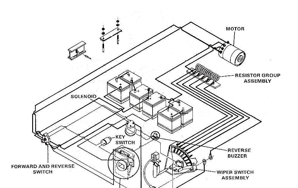
- Components: The diagram identifies and locates every electrical component in the cart, including the battery, motor, controller, solenoid, switches, and lights.
- Connections: It shows how these components are interconnected through a network of wires and connectors, providing a clear understanding of the electrical pathways.
- Circuits: The diagram organizes the electrical system into individual circuits, allowing for easier troubleshooting and repair.
- Power Flow: It illustrates the direction of current flow throughout the system, helping to identify potential voltage drops or overloads.
- Grounding: The diagram indicates the grounding points in the system, which are essential for electrical safety and proper circuit operation.
- Troubleshooting: The diagram serves as a diagnostic tool, helping technicians to pinpoint electrical problems by tracing circuits and identifying faulty components.
- Modifications: For those who want to customize or upgrade their G29 cart, the wiring diagram provides a reference for planning and implementing electrical modifications.
- Safety: By understanding the electrical system through the diagram, owners and operators can ensure that the cart is operated and maintained safely.
- Maintenance: The diagram can assist in scheduling and performing preventive maintenance tasks, such as inspecting connections and testing components.
In conclusion, the key aspects of a Yamaha G29 Wiring Diagram provide a comprehensive understanding of the electrical system, enabling owners, operators, and technicians to troubleshoot, repair, modify, and maintain their golf carts effectively and safely.
Components: The diagram identifies and locates every electrical component in the cart, including the battery, motor, controller, solenoid, switches, and lights.
Within the Yamaha G29 Wiring Diagram, the identification and location of each electrical component is critical for understanding the system’s functionality and performing repairs. The diagram serves as a roadmap, providing a clear representation of how these components are interconnected and interact with each other.
For instance, the battery, as a power source, connects to the controller, which regulates the flow of electricity to the motor. The motor, in turn, powers the wheels, enabling the cart’s movement. Switches control the activation of various functions, such as lights, while the solenoid engages the motor. By understanding the location and purpose of each component through the wiring diagram, technicians can efficiently troubleshoot and resolve electrical issues.
Furthermore, the diagram is invaluable for planning modifications or upgrades to the electrical system. For example, if an owner wants to install additional lighting or accessories, the wiring diagram provides guidance on where to connect these components and how to integrate them into the existing electrical system.
In summary, the comprehensive identification and location of electrical components in the Yamaha G29 Wiring Diagram are essential for troubleshooting, repairs, modifications, and overall understanding of the cart’s electrical system. This knowledge empowers owners and technicians to maintain and operate their carts effectively and safely.
Connections: It shows how these components are interconnected through a network of wires and connectors, providing a clear understanding of the electrical pathways.
Within the Yamaha G29 Wiring Diagram, the depiction of connections between electrical components is paramount. It provides a comprehensive understanding of how these components interact and the pathways through which electricity flows.
For instance, the diagram illustrates how the battery, as the power source, connects to the controller. This connection allows the controller to regulate the flow of electricity to the motor, which in turn powers the wheels and enables the cart’s movement. The diagram also shows how switches control the activation of various functions, such as lights, and how the solenoid engages the motor.
Understanding these connections is crucial for troubleshooting electrical issues. By tracing the pathways in the diagram, technicians can pinpoint the source of a problem and determine which components may be faulty.
Moreover, the diagram is invaluable when making modifications or upgrades to the electrical system. For example, if an owner wants to install additional lighting or accessories, the diagram provides guidance on how to connect these components and integrate them into the existing electrical system.
In summary, the depiction of connections in the Yamaha G29 Wiring Diagram is essential for understanding the electrical system’s functionality, troubleshooting issues, and making modifications. This knowledge empowers owners and technicians to maintain and operate their carts effectively and safely.
Circuits: The diagram organizes the electrical system into individual circuits, allowing for easier troubleshooting and repair.
Within the Yamaha G29 Wiring Diagram, the organization of the electrical system into individual circuits is a critical component that enhances troubleshooting and repair processes.
Each circuit in the diagram represents a specific electrical function, such as the lighting system, motor control, or accessory power. By isolating these functions into separate circuits, the diagram simplifies the tracing of electrical faults and the identification of faulty components.
For instance, if a technician encounters an issue with the cart’s lighting system, they can refer to the wiring diagram and focus on troubleshooting the lighting circuit. This reduces the time and effort required to pinpoint the source of the problem, as they can eliminate other circuits from their investigation.
Furthermore, the organization of circuits in the wiring diagram facilitates the repair process. By isolating faulty circuits, technicians can more easily disconnect and replace malfunctioning components without affecting other systems in the cart.
The practical applications of understanding circuits within the Yamaha G29 Wiring Diagram extend beyond troubleshooting and repair. It also allows owners and technicians to make informed decisions when modifying or upgrading the electrical system.
For example, if an owner wants to install additional lighting or accessories, they can refer to the wiring diagram to identify suitable circuits and determine the appropriate wiring connections.
In summary, the organization of the electrical system into individual circuits in the Yamaha G29 Wiring Diagram is a critical component that streamlines troubleshooting, repair, and modification processes. It provides a structured and logical approach to understanding and maintaining the cart’s electrical system, ensuring its safe and efficient operation.
Power Flow: It illustrates the direction of current flow throughout the system, helping to identify potential voltage drops or overloads.
Within the Yamaha G29 Wiring Diagram, the illustration of power flow is a critical component that facilitates the understanding and maintenance of the electrical system. It provides a visual representation of the pathways through which electricity flows, enabling technicians and owners to identify potential voltage drops or overloads.
Voltage drops occur when there is resistance to the flow of current, causing a decrease in voltage along a circuit. Overloads occur when the current flow exceeds the capacity of a circuit, potentially leading to overheating and damage to components. By understanding the direction of power flow in the wiring diagram, individuals can identify areas where voltage drops or overloads may occur and take appropriate measures to prevent or mitigate these issues.
For instance, if the wiring diagram indicates a long wire run between the battery and the motor, there is a potential for voltage drop due to the resistance of the wire. To address this, a technician may recommend using a thicker gauge wire to reduce resistance and ensure adequate voltage supply to the motor.
Furthermore, the illustration of power flow in the Yamaha G29 Wiring Diagram is essential for troubleshooting electrical problems. By tracing the direction of current flow, technicians can isolate faulty components and identify the source of electrical issues more efficiently.
In summary, the illustration of power flow in the Yamaha G29 Wiring Diagram is a valuable tool for understanding the electrical system’s functionality, preventing potential problems, and troubleshooting electrical issues. It provides a comprehensive view of the electrical pathways, enabling owners and technicians to maintain and operate their carts safely and effectively.
Grounding: The diagram indicates the grounding points in the system, which are essential for electrical safety and proper circuit operation.
Within the context of the Yamaha G29 Wiring Diagram, grounding plays a crucial role in ensuring the electrical system’s safety and proper operation. It provides a reference point for electrical circuits, preventing voltage fluctuations and safeguarding against electrical hazards.
- Safety: Grounding provides a low-resistance path for electrical current to flow back to the source, preventing dangerous voltage buildup in the system. This reduces the risk of electrical shocks and fires.
- Circuit Stability: Grounding provides a stable reference point for electrical circuits, minimizing voltage fluctuations and ensuring consistent operation. This is particularly important for sensitive electronic components.
- Noise Reduction: Grounding helps to reduce electrical noise and interference in the system. By providing a dedicated path for unwanted currents, it prevents these currents from interfering with the operation of other components.
- Fault Detection: Grounding facilitates the detection of electrical faults by providing a reference point for measuring voltage and current. This enables early detection of problems, preventing more severe damage to the electrical system.
In summary, the grounding points indicated in the Yamaha G29 Wiring Diagram are essential for maintaining electrical safety, ensuring circuit stability, reducing noise, and facilitating fault detection. Understanding these grounding points is crucial for proper installation, maintenance, and troubleshooting of the electrical system, ensuring its safe and reliable operation.
Troubleshooting: The diagram serves as a diagnostic tool, helping technicians to pinpoint electrical problems by tracing circuits and identifying faulty components.
The Yamaha G29 Wiring Diagram serves as an essential diagnostic tool for technicians, providing a comprehensive roadmap to troubleshoot electrical problems effectively. By tracing circuits and identifying faulty components, technicians can pinpoint the root cause of electrical issues, enabling efficient repairs and minimizing downtime.
A real-life example of the practical application of the Yamaha G29 Wiring Diagram in troubleshooting involves a technician diagnosing a cart that experiences intermittent loss of power. By referring to the diagram, the technician can systematically trace the electrical circuits to identify any loose connections, damaged wires, or faulty components. This allows for targeted troubleshooting, reducing the time and effort required to resolve the issue.
Understanding the troubleshooting capabilities provided by the Yamaha G29 Wiring Diagram is crucial for maintaining the optimal performance and safety of the golf cart. It empowers technicians with the knowledge to diagnose and repair electrical problems accurately, ensuring the reliable operation of the cart.
Modifications: For those who want to customize or upgrade their G29 cart, the wiring diagram provides a reference for planning and implementing electrical modifications.
Within the context of the Yamaha G29 Wiring Diagram, the aspect of modifications empowers individuals to tailor their golf carts to specific needs and preferences. By understanding the electrical system’s intricacies, owners can plan and execute electrical modifications to enhance the cart’s performance, functionality, or aesthetics.
- Custom Lighting: The wiring diagram serves as a guide for installing additional lighting fixtures, such as headlights, taillights, or underglow lights, allowing for improved visibility and personalization.
- Accessory Integration: The diagram provides insights into connecting various accessories, including sound systems, GPS devices, or charging ports, enhancing the cart’s entertainment and convenience features.
- Performance Upgrades: For those seeking increased speed or torque, the wiring diagram can assist in identifying the appropriate components and modifications, such as upgrading the motor or installing a performance controller.
- Safety Enhancements: Modifications can also focus on safety aspects, such as installing turn signals, brake lights, or a reverse buzzer, promoting increased awareness and reducing the risk of accidents.
Understanding the electrical modifications possible with the Yamaha G29 Wiring Diagram empowers owners to unleash their creativity and customize their golf carts to suit their unique requirements. These modifications not only enhance the cart’s functionality but also reflect the owner’s personal style and preferences.
Safety: By understanding the electrical system through the diagram, owners and operators can ensure that the cart is operated and maintained safely.
The Yamaha G29 Wiring Diagram plays a crucial role in promoting the safe operation and maintenance of Yamaha G29 golf carts. By providing a comprehensive blueprint of the electrical system, the diagram empowers individuals to identify potential hazards, troubleshoot issues, and implement preventive measures.
- Hazard Identification: The wiring diagram helps identify potential electrical hazards, such as exposed wires, loose connections, or overloaded circuits. Understanding these hazards allows owners and operators to take proactive steps to mitigate risks and prevent accidents.
- Troubleshooting: In the event of an electrical issue, the wiring diagram serves as a valuable troubleshooting tool. By tracing circuits and identifying components, individuals can pinpoint the source of the problem and take appropriate corrective actions, ensuring the safe and efficient operation of the cart.
- Preventive Maintenance: Regular inspection and maintenance of the electrical system are essential for safety. The wiring diagram provides a visual guide for these tasks, enabling owners and operators to identify areas that require attention, such as loose terminals, corroded wires, or damaged insulation.
- Compliance with Regulations: Understanding the electrical system through the wiring diagram is crucial for ensuring compliance with safety regulations and industry standards. By adhering to the guidelines outlined in the diagram, owners and operators can minimize the risk of electrical fires, accidents, or injuries.
In conclusion, the safety implications of the Yamaha G29 Wiring Diagram are multifaceted, ranging from hazard identification to preventive maintenance and regulatory compliance. By leveraging the insights provided by the diagram, owners and operators can enhance the operational safety of their golf carts, promoting a safer environment for themselves and others.
Maintenance: The diagram can assist in scheduling and performing preventive maintenance tasks, such as inspecting connections and testing components.
Within the context of Yamaha G29 Wiring Diagram, the aspect of maintenance plays a fundamental role in ensuring the safe and reliable operation of the golf cart. By providing a comprehensive visual representation of the electrical system, the diagram serves as an invaluable tool for owners and operators to schedule and perform preventive maintenance tasks effectively.
- Scheduling Maintenance: The wiring diagram provides a clear overview of the electrical system’s components and their interconnections. This enables owners and operators to establish a regular maintenance schedule based on the manufacturer’s recommendations and the specific operating conditions of the cart.
- Inspecting Connections: Loose or corroded connections can lead to electrical faults and disruptions. The wiring diagram helps identify all electrical connections, allowing for regular inspections and early detection of any potential issues. This proactive approach minimizes the risk of sudden failures and ensures optimal performance.
- Testing Components: The wiring diagram facilitates the testing of individual electrical components, such as batteries, solenoids, and motors. By following the circuit paths outlined in the diagram, technicians can use appropriate testing equipment to assess the functionality of each component and identify any performance issues.
- Troubleshooting and Repairs: In the event of an electrical problem, the wiring diagram serves as a valuable troubleshooting tool. It helps technicians trace circuits, identify faulty components, and determine the root cause of the issue. This enables efficient repairs and minimizes downtime.
In conclusion, the maintenance capabilities provided by the Yamaha G29 Wiring Diagram empower owners and operators to maintain their golf carts proactively, preventing potential problems, ensuring optimal performance, and extending the lifespan of the electrical system.


Related Posts


