Yamaha Big Bear 400 Wiring Diagram defines a diagram that illustrates the electrical system’s components, wire connections, and their respective connections. It functions as a comprehensive resource, enabling individuals to comprehend the electrical system’s layout and connections.
Its significance lies in providing a simplified visual representation, facilitating troubleshooting, repairs, and electrical modifications. For instance, it aids in identifying the source of electrical issues, such as faulty wires, malfunctions, or improper connections.
The diagram has undergone significant developments over time, transitioning from hand-drawn sketches to computer-generated diagrams. This advancement has improved clarity, accuracy, and accessibility, making it indispensable for understanding any ATV’s electrical system.
In the subsequent sections, we will delve deeper into the wiring diagram’s fundamentals, its relevance to varying electrical systems, and practical applications in different scenarios.
Yamaha Big Bear 400 Wiring Diagram provides intricate details about the electrical system of the vehicle. To gain a comprehensive understanding, let’s explore nine key aspects:
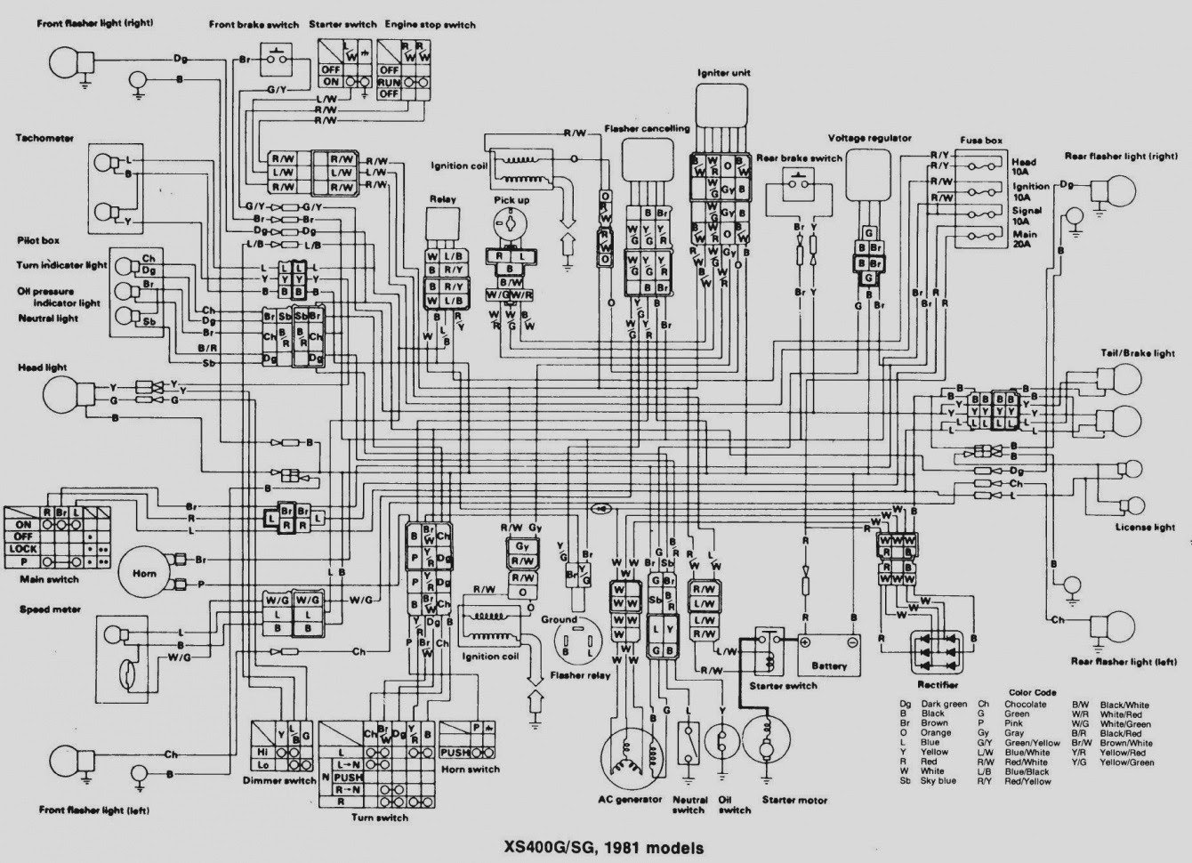
- Components: The diagram identifies all electrical components, including the battery, starter, alternator, ignition system, and lighting.
- Connections: It illustrates the connections between components, showcasing the flow of electricity throughout the system.
- Wire colors and gauges: The diagram specifies the color coding and gauge of wires, aiding in easy identification and troubleshooting.
- Grounding points: It indicates the locations where the electrical system is grounded to the vehicle’s frame.
- Fuses and relays: The diagram shows the placement and function of fuses and relays, which protect the system from overloads and faults.
- Diagnostic points: It includes test points for voltage and continuity checks, facilitating electrical system troubleshooting.
- Troubleshooting guide: Some diagrams include a troubleshooting guide, offering step-by-step instructions for diagnosing common electrical problems.
- Modifications: The diagram serves as a reference for electrical modifications, allowing users to adapt the system to specific needs or preferences.
- Safety: Understanding the wiring diagram is crucial for safe electrical repairs and modifications, preventing potential hazards.
These aspects collectively provide a comprehensive blueprint of the Yamaha Big Bear 400’s electrical system. They enable users to diagnose issues, perform repairs, and make modifications with precision and confidence.
Components
The Yamaha Big Bear 400 Wiring Diagram serves as a comprehensive blueprint of the vehicle’s electrical system. At its core, identifying and understanding the individual components, such as the battery, starter, alternator, ignition system, and lighting, is paramount to comprehending the system’s functionality and interconnections.
The diagram provides a visual representation of how these components are interconnected, allowing users to trace the flow of electricity throughout the system. This understanding is essential for diagnosing electrical issues, performing repairs, and making modifications.
For instance, if the ATV experiences a starting problem, the wiring diagram can guide the user in identifying whether the issue lies with the battery, starter, or ignition system. By understanding the connections between these components, users can systematically troubleshoot and isolate the root cause of the problem.
Moreover, the diagram is invaluable for planning electrical modifications or upgrades. Whether adding accessories like additional lighting or installing a winch, the wiring diagram provides insights into the system’s capacity and the necessary connections to integrate new components seamlessly.
In summary, the identification of individual components within the Yamaha Big Bear 400 Wiring Diagram is critical for understanding the electrical system’s operation. It empowers users to diagnose problems, perform repairs, implement modifications, and make informed decisions regarding their ATV’s electrical system.
Connections
Within the Yamaha Big Bear 400 Wiring Diagram, the depiction of connections between components plays a pivotal role in comprehending the electrical system’s functionality. These connections establish the pathways for electricity to flow, enabling the various components to fulfill their respective functions.
Without a clear understanding of these connections, troubleshooting electrical issues becomes a daunting task. The wiring diagram serves as an invaluable guide, allowing users to trace the flow of electricity and identify potential points of failure.
For instance, if the ATV’s headlights fail to illuminate, the wiring diagram can guide the user in examining the connections between the battery, fuse box, headlight switch, and the headlights themselves. By systematically checking each connection, the user can isolate the source of the problem, whether it be a loose wire, blown fuse, or faulty component.
Moreover, understanding the connections within the wiring diagram is crucial for implementing electrical modifications or upgrades. Whether adding accessories or installing a winch, the diagram provides insights into the system’s capacity and the necessary connections to integrate new components seamlessly.
In summary, the connections illustrated in the Yamaha Big Bear 400 Wiring Diagram are fundamental to understanding the electrical system’s operation. They empower users to diagnose problems, perform repairs, implement modifications, and make informed decisions regarding their ATV’s electrical system.
Wire colors and gauges
Within the comprehensive Yamaha Big Bear 400 Wiring Diagram, the specification of wire colors and gauges plays a vital role in simplifying the identification and troubleshooting of electrical components. By assigning unique colors and gauges to each wire, the diagram provides a systematic approach to understanding the complex electrical system.
- Color Coding: The diagram employs a standardized color coding system, ensuring consistency and ease of identification. Each wire is assigned a specific color, such as red for positive power, black for ground, and yellow for lighting circuits. This color coding enables users to quickly identify the purpose and function of each wire, reducing the risk of misconnections.
- Wire Gauge: The diagram also specifies the gauge, or thickness, of each wire. Wire gauge is crucial for determining the current-carrying capacity of a wire. By matching the wire gauge to the electrical load, users can ensure that the wiring system can handle the required power without overheating or causing damage.
- Circuit Tracing: The color coding and gauge specifications in the diagram facilitate circuit tracing, a technique used to identify the path of electrical current through the system. By following the colored wires and referring to the diagram, users can trace the flow of electricity from the source to the destination, making it easier to locate faults and resolve electrical issues.
- Electrical Modifications: When performing electrical modifications or repairs, the wire color and gauge specifications in the diagram serve as a valuable reference. By understanding the existing wiring system, users can make informed decisions about adding new components or modifying existing circuits, ensuring compatibility and maintaining the integrity of the electrical system.
In conclusion, the Yamaha Big Bear 400 Wiring Diagram’s specification of wire colors and gauges empowers users with a systematic and efficient approach to electrical troubleshooting and modifications. By providing clear visual cues and essential technical information, the diagram enhances the user’s understanding of the electrical system, enabling them to confidently perform repairs, diagnose problems, and make informed decisions.
Grounding points
Within the intricate Yamaha Big Bear 400 Wiring Diagram, the identification of grounding points holds significant importance for understanding the proper functioning of the electrical system. Grounding points serve as crucial connections between the electrical components and the vehicle’s frame, providing a path for the completion of electrical circuits.
The electrical system relies on a continuous flow of current to operate correctly. Grounding points establish a reference point, typically the vehicle’s frame, against which electrical potential is measured. Without proper grounding, electrical circuits cannot complete, resulting in malfunctions or even safety hazards.
The Yamaha Big Bear 400 Wiring Diagram clearly outlines the locations of grounding points, allowing users to inspect and maintain these connections. Loose or corroded grounding points can lead to a variety of electrical issues, such as dim lighting, intermittent component operation, or even complete electrical failure.
By understanding the importance of grounding points and referring to the wiring diagram, users can proactively ensure that these connections are clean, tight, and free of corrosion. Regular inspection and maintenance of grounding points can prevent electrical problems, enhance system reliability, and contribute to the overall safety of the ATV.
In summary, the grounding points identified in the Yamaha Big Bear 400 Wiring Diagram play a critical role in the proper functioning of the electrical system. By providing a reference point for electrical circuits and preventing potential malfunctions, grounding points are essential for maintaining a reliable and safe electrical system.
Fuses and relays
Within the meticulously crafted Yamaha Big Bear 400 Wiring Diagram, fuses and relays serve as indispensable components, safeguarding the electrical system from potential damage caused by overloads and faults.
Fuses act as sacrificial barriers, interrupting the flow of excessive current in the event of an electrical overload. By doing so, they protect sensitive electrical components from damage. Relays, on the other hand, are electromagnetic switches that control the flow of current to various components, enhancing system efficiency and reducing the load on switches.
The Yamaha Big Bear 400 Wiring Diagram meticulously illustrates the placement and function of each fuse and relay within the electrical system. This information is crucial for troubleshooting and maintaining the ATV’s electrical components.
For instance, if a particular electrical component malfunctions, the wiring diagram can guide the user to the corresponding fuse or relay, enabling quick identification of the faulty component and its replacement.
Moreover, understanding the placement and function of fuses and relays is essential for electrical modifications. By referring to the wiring diagram, users can determine the appropriate fuse rating or relay type required for specific modifications, ensuring the safety and reliability of the upgraded system.
In summary, the Yamaha Big Bear 400 Wiring Diagram empowers users to comprehend the critical role of fuses and relays in protecting the electrical system. This understanding enables effective troubleshooting, maintenance, and modification of the ATV’s electrical components.
Diagnostic points
The Yamaha Big Bear 400 Wiring Diagram is an invaluable tool not only for understanding the electrical system’s design but also for diagnosing and troubleshooting potential issues. Diagnostic points, strategically placed throughout the system, play a crucial role in this process.
These test points provide convenient access to specific electrical circuits, allowing technicians and enthusiasts to measure voltage and continuity using a multimeter. Voltage checks help identify if power is reaching a particular component, while continuity checks ensure that electrical pathways are complete and free of breaks or shorts.
For instance, if a headlight is not functioning, the wiring diagram can guide the user to the corresponding diagnostic point. By measuring the voltage at this point, one can determine if the problem lies with the power supply or the headlight itself. Similarly, a continuity check can verify the integrity of the wiring harness connecting the headlight to the electrical system.
Furthermore, diagnostic points are essential for advanced troubleshooting, such as tracing electrical faults or identifying intermittent issues. By systematically checking voltage and continuity at various points in the system, technicians can isolate the source of the problem and make informed decisions about repairs.
In summary, the diagnostic points included in the Yamaha Big Bear 400 Wiring Diagram empower users to efficiently troubleshoot electrical system issues, ensuring the ATV’s optimal performance and reliability.
Troubleshooting guide
Embedded within the comprehensive Yamaha Big Bear 400 Wiring Diagram, the troubleshooting guide serves as an invaluable resource for diagnosing and resolving electrical issues. This guide provides a systematic approach to identifying and rectifying common electrical problems, empowering users to maintain the ATV’s electrical system with confidence.
- Problem Identification: The troubleshooting guide offers a structured process for identifying the root cause of electrical problems. By following the step-by-step instructions, users can narrow down the potential causes, saving valuable time and effort.
- Component Checks: The guide includes instructions for testing individual electrical components, such as fuses, relays, switches, and wiring harnesses. This enables users to pinpoint faulty components and replace them as necessary, restoring the electrical system to optimal functionality.
- Circuit Analysis: The troubleshooting guide provides a methodical approach to analyzing electrical circuits. Users can follow the instructions to trace the flow of electricity through the system, identify breaks or shorts, and ensure proper circuit continuity.
- Real-Life Scenarios: The guide offers troubleshooting scenarios based on common electrical problems encountered in real-world applications. These scenarios provide practical examples, helping users apply the troubleshooting process to specific situations.
By incorporating a troubleshooting guide into the Yamaha Big Bear 400 Wiring Diagram, Yamaha empowers users to diagnose and resolve electrical issues with greater efficiency and accuracy. This guide serves as a valuable tool for maintaining the ATV’s electrical system, ensuring optimal performance and reliability.
Modifications
Within the context of the Yamaha Big Bear 400 Wiring Diagram, the section on modifications holds significant importance. This section provides detailed guidance and information for users seeking to adapt the electrical system to their specific requirements and preferences. By leveraging the diagram as a reference, users can confidently undertake electrical modifications, ensuring compatibility and maintaining system integrity.
The Yamaha Big Bear 400 Wiring Diagram serves as a comprehensive roadmap for electrical modifications. It empowers users to understand the existing electrical architecture, identify potential connection points, and plan modifications accordingly. Real-life examples of modifications include installing additional lighting systems, upgrading the audio system, or integrating accessories such as winches or GPS devices.
The practical applications of understanding modifications within the wiring diagram are immense. Users can customize their ATVs to suit their unique riding styles, enhance safety features, or improve overall functionality. By following the guidelines provided in the diagram, users can avoid potential electrical hazards, ensure proper system operation, and maintain the ATV’s reliability.
In summary, the section on modifications in the Yamaha Big Bear 400 Wiring Diagram is a crucial component for users seeking to adapt their electrical systems. By providing a clear understanding of the system’s architecture and the necessary steps for modifications, the diagram empowers users to enhance the functionality and personalization of their ATVs.
Safety
Within the realm of electrical systems, the Yamaha Big Bear 400 Wiring Diagram stands as a cornerstone of safety. Understanding this diagram is paramount for executing safe electrical repairs and modifications, effectively preventing potential hazards that could jeopardize the user’s well-being and the integrity of the ATV.
The wiring diagram serves as a comprehensive blueprint, detailing the intricate connections and components that constitute the electrical system. By thoroughly comprehending this diagram, users gain invaluable insights into the system’s operation, enabling them to identify and address electrical issues with precision and confidence.
Real-life examples underscore the crucial role of the wiring diagram in ensuring safety. Consider a scenario where a user attempts to install additional lighting without consulting the diagram. This haphazard approach could lead to incorrect wire connections, potentially causing electrical shorts, fires, or even damage to sensitive components.
Conversely, a user who meticulously follows the wiring diagram can ensure proper connections, safeguarding against such hazards. The diagram provides clear instructions on wire routing, fuse selection, and grounding points, empowering users to execute modifications safely and effectively.
In summary, the Yamaha Big Bear 400 Wiring Diagram is an indispensable tool for maintaining electrical safety. By providing a comprehensive understanding of the system’s architecture, the diagram empowers users to perform repairs and modifications with confidence, minimizing the risk of electrical hazards and ensuring the ATV’s optimal performance.


Related Posts


