A wiring schematic for trailer lights is a diagram that illustrates the electrical connections necessary to install and operate trailer lighting systems. It typically includes components such as wires, connectors, fuses, and light fixtures, providing a visual representation of the electrical circuitry.
Wiring schematics are crucial for ensuring the safety and functionality of trailer lighting systems. They guide installers in making proper connections, preventing potential electrical hazards and ensuring that lights operate correctly. Historically, the advent of standardized wiring color codes simplified the process of electrical troubleshooting and maintenance.
This article delves into the essential components of a trailer lighting wiring schematic, highlighting its importance and discussing the key historical developments that have shaped its current form.
Understanding the essential aspects of a “Wiring Schematic For Trailer Lights” is paramount for ensuring the proper installation, maintenance, and safety of trailer lighting systems. These aspects encompass the fundamental components, principles, and considerations involved in creating and interpreting wiring schematics.
- Components: Wires, connectors, fuses, light fixtures
- Purpose: Visual representation of electrical connections
- Benefits: Simplifies installation, troubleshooting, and maintenance
- Safety: Ensures proper connections, preventing electrical hazards
- Standardization: Color codes facilitate troubleshooting and maintenance
- Circuitry: Depicts the flow of electricity through the system
- Testing: Essential for verifying the functionality of the system
- Documentation: Provides a permanent record of the electrical design
- Customization: Tailored to specific trailer configurations and lighting requirements
- Compliance: Adherence to regulatory standards ensures safety and legality
These aspects are interconnected and essential for understanding the design, implementation, and maintenance of trailer lighting wiring schematics. They provide a comprehensive framework for ensuring the safe and reliable operation of these critical systems.
Components
In the context of a “Wiring Schematic for Trailer Lights,” the componentswires, connectors, fuses, and light fixturesplay a critical role in ensuring the proper functioning and safety of the electrical system. These components are interconnected and interdependent, forming the backbone of the trailer lighting system.
Wires serve as the pathways for electrical current to flow from the power source to the light fixtures. Connectors establish secure electrical connections between wires, ensuring a continuous flow of electricity. Fuses act as safety devices, protecting the electrical system from overcurrent conditions that could lead to damage or fire. Light fixtures are the of the electrical current, converting it into visible light.
For instance, in a typical trailer lighting system, the wires connect the battery to the trailer’s electrical panel, which houses the fuses and connectors. The fuses safeguard the system from electrical faults, while the connectors provide a reliable connection between the wires and the light fixtures. The light fixtures then emit the necessary lighting signals, ensuring visibility and safety on the road.
Understanding the relationship between these components is crucial for designing, installing, and maintaining trailer lighting systems. It enables technicians to troubleshoot electrical issues efficiently and make informed decisions regarding system upgrades or modifications. By adhering to wiring schematics and industry standards, professionals can ensure the safety, functionality, and longevity of the trailer lighting system.
Purpose
In the context of “Wiring Schematic For Trailer Lights,” the purpose of visual representation of electrical connections holds paramount importance. A wiring schematic serves as a graphical depiction of the electrical circuitry, providing a clear and concise representation of the interconnected electrical components and their relationships.
This visual representation plays a critical role in the design, installation, troubleshooting, and maintenance of trailer lighting systems. By providing a comprehensive overview of the electrical connections, wiring schematics enable technicians to understand the flow of electricity and identify potential issues quickly and efficiently. For instance, a well-drawn wiring schematic can help identify open circuits, short circuits, and other electrical faults, reducing the time and effort required for troubleshooting.
Furthermore, the visual representation of electrical connections is essential for ensuring the safety and reliability of trailer lighting systems. By adhering to industry standards and best practices, wiring schematics help ensure that electrical connections are made correctly, minimizing the risk of electrical hazards such as fires or shocks. This is particularly important for trailers that are used to transport hazardous materials or in environments where electrical safety is paramount.
In summary, the visual representation of electrical connections is a critical component of “Wiring Schematic For Trailer Lights.” It provides a clear and concise overview of the electrical circuitry, enabling technicians to design, install, troubleshoot, and maintain trailer lighting systems efficiently and safely. Understanding the purpose and importance of visual representation in wiring schematics is essential for ensuring the proper functioning and longevity of these critical systems.
Benefits
Within the context of “Wiring Schematic For Trailer Lights,” the benefits of simplified installation, troubleshooting, and maintenance are tightly intertwined with the very nature and purpose of wiring schematics. These benefits stem from the visual representation of electrical connections provided by wiring schematics, which offers a clear and concise overview of the electrical circuitry.
During the installation phase, wiring schematics serve as a comprehensive guide, enabling technicians to understand the intended layout and connections of the electrical system. By providing a visual roadmap, wiring schematics minimize the risk of errors and ensure that all components are connected correctly. This not only simplifies the installation process but also reduces the likelihood of electrical faults or malfunctions.
In the event of troubleshooting, wiring schematics become invaluable diagnostic tools. When an electrical issue arises, technicians can refer to the schematic to quickly identify the affected circuit or component. This targeted approach reduces troubleshooting time and effort, leading to faster resolution of the problem. Additionally, wiring schematics provide a valuable reference point for maintenance tasks, ensuring that electrical connections are inspected and serviced regularly to prevent future issues.
The practical applications of this understanding are evident in various real-life scenarios. For instance, in the automotive industry, wiring schematics are essential for the design, installation, and maintenance of electrical systems in vehicles, including trailers. By providing a visual representation of the electrical circuitry, wiring schematics enable technicians to efficiently diagnose and repair electrical faults, ensuring the safety and reliability of vehicles on the road.
In summary, the benefits of simplified installation, troubleshooting, and maintenance are critical components of “Wiring Schematic For Trailer Lights.” Wiring schematics provide a visual representation of electrical connections, which enables technicians to understand, install, troubleshoot, and maintain trailer lighting systems efficiently and effectively. This understanding is essential for ensuring the safety, reliability, and longevity of these critical systems.
Safety
Within the context of “Wiring Schematic For Trailer Lights,” the aspect of “Safety: Ensures proper connections, preventing electrical hazards” takes precedence. Wiring schematics play a pivotal role in ensuring the safety and reliability of trailer lighting systems by providing a visual representation of the electrical connections. This enables technicians to understand, install, and maintain the electrical system effectively, minimizing the risk of electrical hazards.
- Prevents Short Circuits: Wiring schematics help ensure that electrical wires are connected correctly, preventing short circuits that could lead to overheating, fires, or damage to electrical components.
- Eliminates Open Circuits: By providing a clear overview of the electrical connections, wiring schematics help identify and eliminate open circuits, ensuring a continuous flow of electricity throughout the system.
- Reduces Fire Risks: Proper connections and the elimination of electrical hazards minimize the risk of electrical fires, safeguarding the trailer, its contents, and the safety of individuals in the vicinity.
- Prevents Electrical Shocks: Wiring schematics guide technicians in making secure electrical connections, reducing the likelihood of loose or exposed wires that could pose a risk of electrical shocks.
In summary, the aspect of “Safety: Ensures proper connections, preventing electrical hazards” is of paramount importance in the context of “Wiring Schematic For Trailer Lights.” Wiring schematics provide a visual representation of electrical connections, enabling technicians to design, install, troubleshoot, and maintain trailer lighting systems safely and efficiently. Understanding the safety implications of proper electrical connections and the role of wiring schematics in mitigating electrical hazards is essential for ensuring the safety and reliability of these critical systems.
## Standardization: Color codes facilitate troubleshooting and maintenance
Within the context of “Wiring Schematic For Trailer Lights,” the standardization of color codes plays a critical role in facilitating troubleshooting and maintenance. Color codes provide a consistent and universal language for electrical connections, enabling technicians to quickly and accurately identify wires, terminals, and components.
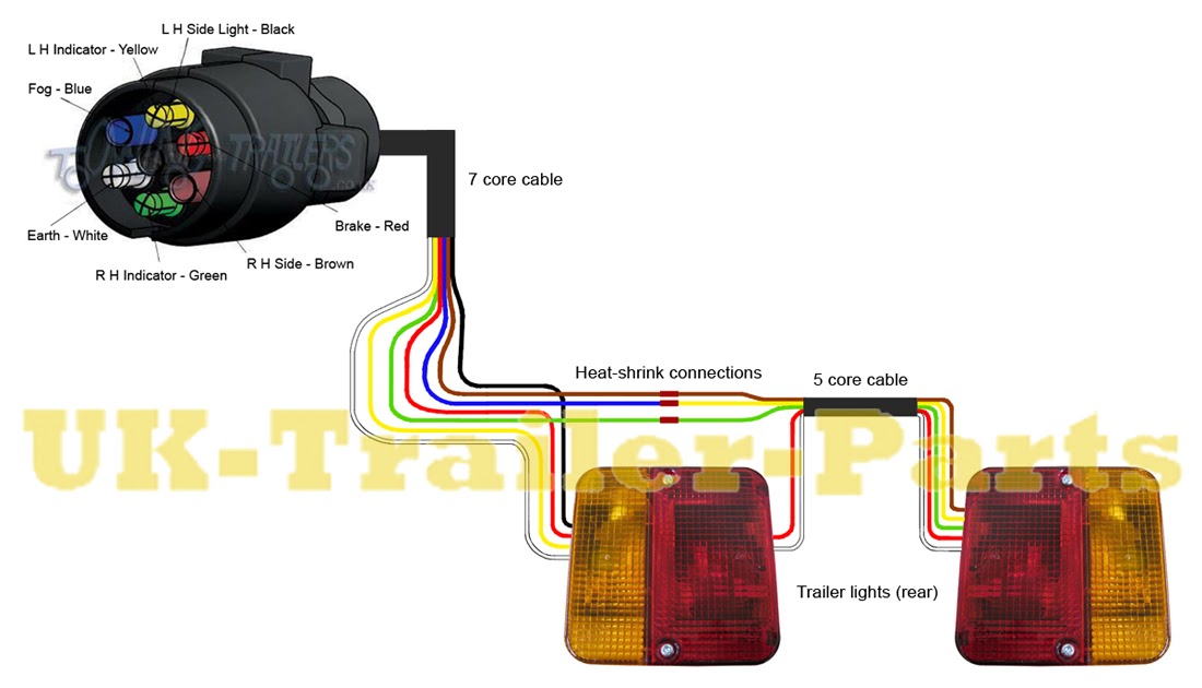
This standardization reduces the likelihood of errors during installation and maintenance, as technicians can rely on the color code to determine the function of each wire. For instance, in trailer lighting systems, the brown wire typically indicates the taillights, while the yellow wire represents the turn signals. By adhering to these color codes, technicians can easily trace and identify electrical connections, reducing troubleshooting time and effort.
The practical applications of standardized color codes are evident in various industries. In automotive electrical systems, color codes are used to identify wires for headlights, brake lights, and other critical components. This standardization enables technicians to quickly diagnose and repair electrical faults, ensuring the safety and reliability of vehicles on the road.
Circuitry
Within the context of “Wiring Schematic For Trailer Lights,” the aspect of “Circuitry: Depicts the flow of electricity through the system” holds great significance. Wiring schematics serve as visual representations of electrical circuits, providing a clear understanding of how electricity flows through the system.
- Components and Connections: Wiring schematics depict the electrical components and their connections, illustrating the pathway for the flow of electricity. This includes batteries, fuses, switches, and lighting fixtures.
- Current Flow: Schematics indicate the direction of current flow, showing how electricity travels from the power source, through the components, and back to the ground.
- Voltage and Resistance: Schematics may also include information about voltage and resistance at various points in the circuit, providing insights into the electrical characteristics of the system.
- Grounding: Grounding is crucial for electrical safety. Schematics show how components are grounded, ensuring proper electrical connections and preventing electrical hazards.
Understanding the circuitry and flow of electricity is essential for designing, installing, troubleshooting, and maintaining trailer lighting systems. By providing a visual representation of the electrical connections, wiring schematics enable technicians to comprehend the system’s operation and make informed decisions to ensure its proper functioning and safety.
Testing
Within the domain of “Wiring Schematic for Trailer Lights,” testing emerges as a pivotal step in the quality assurance process. It ensures that trailer lighting systems meet safety standards, operate reliably, and fulfill their intended purpose. This comprehensive evaluation involves a systematic approach to verifying the functionality of various components and the overall system.
- Component Testing: Individual components, such as light fixtures, fuses, and wiring harnesses, undergo rigorous testing to assess their performance and durability. This includes simulating real-world conditions and applying specific test parameters to identify potential defects or weaknesses.
- Circuit Verification: Using specialized equipment, technicians verify the continuity and integrity of electrical circuits. This involves checking for proper connections, grounding, and the absence of short circuits or open circuits that could compromise system functionality.
- System Performance: Once individual components and circuits are validated, the entire system is tested under simulated or actual operating conditions. This includes evaluating light output, signal timing, and response to various inputs to ensure the system meets the required specifications.
- Environmental Testing: Trailer lighting systems are subjected to a range of environmental conditions, including extreme temperatures, moisture, vibration, and electromagnetic interference. Environmental testing assesses the system’s ability to withstand these conditions and maintain its functionality.
By performing thorough testing, manufacturers and technicians can identify and rectify any issues before the trailer lighting systems are deployed in the field. This proactive approach minimizes the risk of system failures, enhances safety on the road, and ensures that trailer lights operate as intended, providing clear and effective signaling for other drivers.
Documentation
Within the context of “Wiring Schematic For Trailer Lights,” documentation plays a crucial role in maintaining a permanent record of the electrical design. This documentation serves various purposes, including providing a reference for future modifications or repairs, facilitating collaboration among multiple parties involved in the project, and ensuring compliance with industry standards and regulations.
- Design Specifications: Documentation includes detailed specifications outlining the electrical design, including component selection, wire gauges, and circuit layouts. This information is vital for replicating the design or troubleshooting issues.
- Installation Instructions: Step-by-step instructions guide technicians through the installation process, ensuring proper connections and adherence to safety guidelines.
- Maintenance Records: Documentation provides a centralized location to record maintenance activities, such as inspections, repairs, and upgrades. This history helps identify trends, predict future maintenance needs, and extend the system’s lifespan.
- Compliance Verification: Documentation serves as evidence of compliance with industry standards and regulatory requirements. It demonstrates that the electrical design meets the necessary safety and performance criteria.
The comprehensive documentation of trailer lighting wiring schematics is essential for ensuring the safety, reliability, and longevity of these systems. It provides a valuable reference point for troubleshooting, maintenance, and future modifications, contributing to the efficient operation of trailers and the safety of all road users.
Customization
In the realm of “Wiring Schematic For Trailer Lights,” customization emerges as a critical component, allowing for the adaptation of lighting systems to meet the unique configurations and lighting requirements of diverse trailers. This customization ensures that each trailer’s lighting system operates optimally, providing enhanced safety and functionality.
The relationship between customization and trailer lighting wiring schematics is bidirectional. On the one hand, specific trailer configurations and lighting requirements drive the customization of wiring schematics. For instance, a refrigerated trailer may require additional lighting fixtures for its cargo area, necessitating modifications to the wiring schematic to accommodate these additional components. On the other hand, well-designed wiring schematics facilitate the customization process by providing a flexible framework that can be adapted to different trailer configurations and lighting needs.
Real-life examples of customization in trailer lighting wiring schematics abound. Consider a construction trailer equipped with specialized lighting for night-time operations. The wiring schematic for such a trailer would be customized to include additional circuits and fuse protection for the high-intensity work lights. Similarly, a flatbed trailer designed to transport oversized cargo may require modified wiring to power auxiliary lighting systems that illuminate the extended load.
The practical applications of this understanding extend to various industries that rely on trailers for transportation and specialized operations. By tailoring wiring schematics to specific requirements, businesses can optimize the safety and efficiency of their trailer fleets. Moreover, customized wiring schematics enhance troubleshooting and maintenance processes, as technicians can easily identify and address issues specific to the trailer’s configuration and lighting needs.
Compliance
In the context of “Wiring Schematic For Trailer Lights,” compliance with regulatory standards holds paramount importance in ensuring the safety and legality of trailer lighting systems. Regulatory standards establish a framework of requirements that govern the design, installation, and operation of these systems, with the primary objective of enhancing road safety and minimizing potential hazards.
Wiring schematics play a crucial role in ensuring compliance with regulatory standards. They provide a blueprint for the electrical system, outlining the layout, connections, and specifications of the lighting components. By adhering to these schematics, manufacturers and installers can create lighting systems that meet the required safety and performance criteria.
Real-life examples of compliance in trailer lighting wiring schematics include adherence to standards such as SAE J592 and FMVSS 108. These standards specify the minimum requirements for lighting systems, including the number, placement, and intensity of lights, as well as the electrical characteristics and safety features. By meeting these standards, trailer lighting systems ensure proper visibility, signaling, and hazard warning, contributing to the overall safety of road users.
The practical applications of this understanding extend to various industries that utilize trailers for transportation and specialized operations. By ensuring compliance with regulatory standards through the use of accurate wiring schematics, businesses can mitigate legal liabilities, protect their assets, and maintain a positive safety record. Moreover, compliance fosters a culture of responsibility and accountability, promoting ethical practices and contributing to the broader goal of enhancing road safety for all.


Related Posts


