A wiring one-wire alternator diagram is a simplified schematic that illustrates the basic electrical connections required to properly install and operate a one-wire alternator in a vehicle’s electrical system. It typically includes a diagram of the alternator, battery, voltage regulator, and other relevant components, along with the wiring connections between them.
One-wire alternators are commonly used in automotive applications due to their simplicity and ease of installation. They require only one wire to connect to the vehicle’s electrical system, which makes them ideal for vehicles with limited wiring or for those who want to simplify their electrical setup. Additionally, one-wire alternators are known for their reliability and durability, making them a popular choice for off-road and heavy-duty applications.
The development of the one-wire alternator has its roots in the early days of automotive electrical systems. In the 1950s, alternators began to replace generators as the primary source of electrical power in vehicles. However, early alternators required multiple wires to connect to the vehicle’s electrical system, which could be complex and time-consuming to install.
In the 1960s, the first one-wire alternators were developed, which greatly simplified the installation process. These early one-wire alternators used a voltage regulator to control the output voltage, and they required only one wire to connect to the battery. Over the years, one-wire alternators have been refined and improved, and they are now widely used in automotive applications.
In this article, we will explore the wiring diagram of a one-wire alternator in more detail. We will discuss the different components involved, the electrical connections, and the operation of the alternator. We will also provide some troubleshooting tips and tricks to help you keep your one-wire alternator running smoothly.
Understanding the essential aspects of a wiring one-wire alternator diagram is crucial for proper installation, maintenance, and troubleshooting. These aspects encompass various dimensions, including electrical connections, components, and functionality.
- Circuitry: Layout and configuration of electrical pathways.
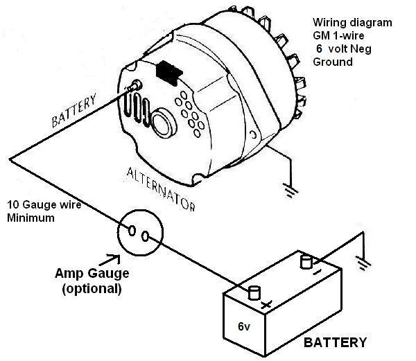
- Connections: Wiring scheme, including wire gauge, color coding, and terminal connections.
- Components: Alternator, battery, voltage regulator, and other electrical devices.
- Current flow: Path of electrical current through the circuit.
- Functionality: Operation and purpose of the one-wire alternator system.
- Installation: Proper placement and mounting of alternator and components.
- Maintenance: Regular checks and servicing to ensure optimal performance.
- Troubleshooting: Identifying and resolving electrical faults or malfunctions.
- Safety: Precautions and guidelines for safe handling and operation.
These aspects are interconnected and play vital roles in the overall performance and reliability of the one-wire alternator system. A clear understanding of these aspects enables effective troubleshooting, maintenance, and optimization of the electrical system.
Circuitry
In the context of a wiring one-wire alternator diagram, the circuitry refers to the layout and configuration of electrical pathways that enable the proper functioning of the alternator system. It involves the arrangement of electrical components, such as the alternator, battery, voltage regulator, and wiring, to facilitate the flow of electrical current.
The circuitry of a wiring one-wire alternator diagram plays a critical role in determining the performance and efficiency of the electrical system. A well-designed circuitry ensures that the alternator generates the required electrical power and that it is properly distributed to the vehicle’s electrical components. It also helps prevent electrical faults, such as short circuits and overloads, which can damage the alternator or other electrical devices.
Real-life examples of circuitry in a wiring one-wire alternator diagram include the use of heavy-gauge wire to minimize resistance and power loss, the incorporation of fuses or circuit breakers to protect against overcurrents, and the use of diodes to prevent reverse current flow. Understanding the circuitry of a wiring one-wire alternator diagram is essential for proper installation, maintenance, and troubleshooting of the electrical system. It enables technicians to identify and resolve electrical faults, optimize the performance of the alternator, and ensure the safe and reliable operation of the vehicle’s electrical system.
In summary, the circuitry of a wiring one-wire alternator diagram is a critical component that determines the functionality, efficiency, and reliability of the alternator system. A clear understanding of the circuitry enables effective troubleshooting, maintenance, and optimization of the electrical system, ensuring the proper operation of the vehicle’s electrical components.
Connections
In the context of a wiring one-wire alternator diagram, the connections refer to the wiring scheme, including wire gauge, color coding, and terminal connections, which establish the electrical pathways between the alternator, battery, voltage regulator, and other components. These connections are critical for ensuring the proper operation and functionality of the alternator system.
The wiring scheme outlines the specific arrangement and routing of wires within the alternator system. It determines the path of electrical current flow and the interconnection of components. The wire gauge, which refers to the thickness and capacity of the wires used, is crucial for minimizing resistance and power loss, especially in high-current applications. Color coding is often employed to simplify the identification and tracing of wires, facilitating installation and troubleshooting. Terminal connections, which involve the physical attachment of wires to the alternator, battery, and other components, must be secure and properly insulated to prevent electrical faults.
Understanding the connections in a wiring one-wire alternator diagram is essential for proper installation, maintenance, and troubleshooting of the electrical system. Correctly following the wiring scheme and ensuring proper connections are critical to avoid electrical problems, such as short circuits, overloads, and alternator malfunctions. Additionally, knowledge of the wiring scheme enables technicians to trace and identify electrical faults, facilitating efficient troubleshooting and repairs.
Real-life examples of connections in a wiring one-wire alternator diagram include the use of heavy-gauge wire to connect the alternator to the battery, ensuring minimal voltage drop during high-current charging. Color coding, such as red for positive connections and black for negative connections, is commonly used to simplify the identification of wires and prevent incorrect connections. Terminal connections are typically secured using crimp connectors or solder joints to ensure a reliable electrical connection.
In summary, the connections in a wiring one-wire alternator diagram play a critical role in the proper functioning of the alternator system. Understanding the wiring scheme, wire gauge, color coding, and terminal connections is essential for effective installation, maintenance, and troubleshooting of the electrical system. This understanding enables technicians to optimize the performance of the alternator, prevent electrical faults, and ensure the reliable operation of the vehicle’s electrical components.
Components
In the context of a wiring one-wire alternator diagram, the components alternator, battery, voltage regulator, and other electrical devices play critical roles in the generation, regulation, and distribution of electrical power within the vehicle’s electrical system. Understanding their relationship is key to comprehending the functionality and operation of the one-wire alternator system.
The alternator is the central component responsible for generating electrical power. It converts mechanical energy from the engine into electrical energy, which is then supplied to the battery and other electrical devices. The battery stores electrical energy and provides power when the alternator is not operating, such as when the engine is off. The voltage regulator monitors the electrical system voltage and adjusts the alternator’s output accordingly, ensuring that the battery receives the correct voltage for charging and that other electrical devices operate within their specified voltage range.
Other electrical devices connected to the one-wire alternator system may include lights, ignition systems, audio systems, and various electronic modules. These devices consume electrical power generated by the alternator and stored in the battery. A wiring one-wire alternator diagram outlines the electrical connections between these components, ensuring that power is distributed efficiently and safely throughout the vehicle’s electrical system.
Real-life examples of components within a wiring one-wire alternator diagram include the use of a high-output alternator to meet the increased electrical demands of modern vehicles with numerous electronic devices. Deep-cycle batteries are often used in applications requiring sustained electrical power, such as in recreational vehicles or marine electrical systems. Voltage regulators with advanced features, such as programmable voltage set points and temperature compensation, are employed to optimize the charging system’s performance and protect sensitive electrical devices from voltage spikes or fluctuations.
Understanding the relationship between components in a wiring one-wire alternator diagram is crucial for effective troubleshooting and maintenance of the electrical system. By identifying the specific components involved in a malfunction or issue, technicians can quickly isolate and resolve the problem. Additionally, a clear understanding of component connections and their roles enables the optimization of the electrical system’s performance, ensuring reliable power supply and preventing premature component failures.
Current flow
In the realm of “Wiring One Wire Alternator Diagram”, understanding current flow, the path of electrical current through the circuit, holds immense significance. It is analogous to the circulatory system in our bodies, ensuring a continuous flow of electricity to power various components and maintain the vehicle’s electrical health.
- Conductors and Insulators: Electrical current, a stream of charged particles, requires a conductive path to flow. Conductors, such as copper wires, facilitate this flow, while insulators, like rubber or plastic, prevent current leakage.
- Grounding: The electrical circuit needs a reference point, known as ground, to complete the flow of current. Typically, the vehicle’s chassis serves as the grounding point, providing a path for current to return to the source.
- Fuses and Circuit Breakers: To protect the circuit from overcurrents, fuses or circuit breakers act as safety switches. They interrupt the current flow when it exceeds a predetermined level, safeguarding the electrical system from damage.
- Diodes: Diodes, semiconductor devices, allow current flow in only one direction. They prevent reverse current flow, ensuring proper operation of the alternator and other components.
Grasping these facets of current flow empowers technicians and enthusiasts alike to effectively troubleshoot electrical issues, optimize performance, and ensure the longevity of their vehicle’s electrical system. It’s akin to deciphering the electrical blueprint of the vehicle, enabling informed decision-making and proactive maintenance.
Functionality
Within the intricate network of an automobile’s electrical system, the one-wire alternator stands as a cornerstone, responsible for generating and regulating the flow of electricity. Its functionality is deeply intertwined with the “Wiring One Wire Alternator Diagram,” a schematic representation that serves as a blueprint for its proper installation and operation.
The one-wire alternator system draws its name from its simplified electrical connections. Unlike conventional alternators that require multiple wires for excitation, voltage regulation, and output, the one-wire alternator ingeniously combines these functions into a single wire, significantly reducing complexity and installation time. This streamlined approach makes it a popular choice for both automotive and marine applications, where simplicity and reliability are paramount.
Understanding the functionality of the one-wire alternator system is crucial for interpreting the Wiring One Wire Alternator Diagram. The diagram outlines the path of electrical current from the alternator, through the battery, and back to the alternator, completing the charging circuit. It also depicts the role of the voltage regulator, which monitors and adjusts the alternator’s output voltage to ensure optimal battery charging and prevent overcharging. By deciphering the diagram and comprehending the underlying functionality, technicians and enthusiasts gain the ability to troubleshoot electrical faults, optimize performance, and extend the lifespan of their electrical systems.
In summary, the functionality of the one-wire alternator system is inextricably linked to the Wiring One Wire Alternator Diagram. The diagram serves as a visual guide, translating the system’s operation into a tangible representation, empowering individuals to delve into the intricacies of their vehicle’s electrical system with confidence and precision.
Installation
In the realm of automotive electrical systems, the “Wiring One Wire Alternator Diagram” serves as a vital blueprint for configuring and connecting the alternator, battery, voltage regulator, and associated components. The proper placement and mounting of these components play a critical role in ensuring the efficient operation and longevity of the electrical system. This section delves into the intricate relationship between “Installation: Proper placement and mounting of alternator and components” and “Wiring One Wire Alternator Diagram,” shedding light on their interdependence and significance.
The installation process begins with selecting the appropriate alternator for the specific vehicle and application. Factors such as amperage output, voltage regulation, and physical dimensions must be carefully considered to ensure compatibility and optimal performance. The alternator’s mounting location is crucial, as it directly impacts belt alignment, tension, and cooling. The Wiring One Wire Alternator Diagram provides precise guidance on mounting brackets, bolt sizes, and clearances to achieve proper alignment and minimize vibrations.
Beyond the alternator, the battery’s placement and mounting are equally important. The battery serves as the primary energy storage device, providing power when the alternator is not operating. The diagram specifies the ideal battery location for optimal cable routing, minimizing voltage drop and ensuring reliable starting capability. Additionally, proper grounding of the battery and alternator is essential for completing the electrical circuit and preventing electrical faults.
Understanding the connection between “Installation: Proper placement and mounting of alternator and components” and “Wiring One Wire Alternator Diagram” empowers individuals to perform accurate installations, troubleshoot electrical problems, and optimize the performance of their vehicle’s electrical system. By adhering to the guidelines outlined in the diagram, enthusiasts and technicians can ensure that the alternator and its components are properly positioned, securely mounted, and effectively connected, leading to a reliable and efficient electrical system.
Maintenance
Within the comprehensive framework of “Wiring One Wire Alternator Diagram,” meticulous maintenance practices stand as a cornerstone for ensuring sustained peak performance and longevity of the electrical system. Regular checks and servicing, guided by the diagram’s insights, empower individuals to proactively identify and address potential issues, mitigating costly repairs and maximizing the alternator’s lifespan.
- Belt Tension: The serpentine belt, responsible for driving the alternator, requires periodic tension checks and adjustments. A loose belt can lead to slippage, reduced alternator output, and premature belt failure. Conversely, an overtightened belt can strain the alternator’s bearings and cause premature wear.
- Electrical Connections: Loose or corroded electrical connections can impede current flow, compromising alternator performance. Regular inspection and cleaning of terminals, connectors, and wiring ensure optimal electrical contact and prevent voltage drop.
- Voltage Output: Monitoring the alternator’s voltage output is crucial for assessing its health and identifying potential issues. Using a voltmeter to measure voltage at the battery terminals while the engine is running can reveal overcharging or undercharging conditions, prompting further investigation.
- Bearing Inspection: Worn or damaged alternator bearings can generate excessive noise, vibration, and heat, affecting the alternator’s efficiency and lifespan. Periodically listening for unusual noises or excessive vibration can provide early warning signs of bearing issues.
By adhering to a proactive maintenance regimen outlined in the “Wiring One Wire Alternator Diagram,” individuals can safeguard their vehicle’s electrical system, prevent unexpected breakdowns, and extend the alternator’s service life. Regular checks and servicing empower them to maintain optimal alternator performance, ensuring a reliable and efficient flow of electricity throughout the vehicle’s electrical components.
Troubleshooting
Within the intricate landscape of “Wiring One Wire Alternator Diagram,” troubleshooting stands as a critical pillar, empowering individuals to identify and resolve electrical faults or malfunctions, ensuring the smooth operation and longevity of the electrical system. The diagram serves as an indispensable guide during troubleshooting, providing a detailed roadmap of the alternator’s components and their interconnections.
Electrical faults can manifest in various forms, ranging from diminished alternator output to complete electrical failure. By understanding the cause-and-effect relationships outlined in the Wiring One Wire Alternator Diagram, individuals can systematically diagnose and rectify these issues. For instance, a loose or corroded electrical connection can lead to voltage drop, impairing the alternator’s ability to charge the battery and power electrical components. The diagram pinpoints the location of these connections, enabling targeted inspection and repair.
Real-life examples further solidify the connection between troubleshooting and the Wiring One Wire Alternator Diagram. A common issue is a faulty voltage regulator, which can cause overcharging or undercharging of the battery. The diagram clearly depicts the voltage regulator’s location and its connections to the alternator and battery, allowing technicians to quickly identify and replace the defective component. Another scenario involves a worn alternator belt, which can lead to slippage and reduced alternator output. The diagram provides precise specifications for the belt’s tension and routing, enabling proper adjustment or replacement to restore optimal performance.
The practical applications of troubleshooting within the context of the Wiring One Wire Alternator Diagram are immense. Empowering individuals with the knowledge and skills to diagnose and resolve electrical faults translates into enhanced vehicle reliability, reduced downtime, and cost savings on repairs. Moreover, it fosters a deeper understanding of the vehicle’s electrical system, enabling proactive maintenance and preventive measures to minimize the likelihood of future problems. The Wiring One Wire Alternator Diagram serves as a valuable tool, guiding individuals through the troubleshooting process, ensuring a comprehensive and systematic approach to maintaining a healthy and efficient electrical system.
Safety
The “Wiring One Wire Alternator Diagram” assumes critical importance when considering the safety precautions and guidelines for handling and operating the electrical system. It serves as a comprehensive guide, outlining the necessary steps to ensure the safe installation, operation, and maintenance of the alternator and its associated components. Understanding and adhering to these safety measures minimize the risk of electrical hazards, personal injury, and damage to the vehicle’s electrical system.
The diagram provides clear instructions on how to properly connect and disconnect the alternator, highlighting potential hazards and recommending appropriate personal protective equipment. It also emphasizes the importance of using insulated tools, wearing gloves, and following proper grounding procedures to prevent electrical shock. By incorporating safety considerations into the wiring diagram, individuals are better equipped to handle and operate the alternator system safely, reducing the likelihood of accidents or malfunctions.
Real-life examples further illustrate the practical significance of safety precautions within the Wiring One Wire Alternator Diagram. For instance, the diagram specifies the use of heat-resistant gloves when handling the alternator during or shortly after operation, as it can reach high temperatures. Additionally, it warns against touching or coming into contact with exposed electrical terminals or wires, emphasizing the risk of electrical burns or shock. These safety measures are crucial for ensuring the well-being of individuals working on or around the alternator system.
The practical applications of understanding the safety precautions and guidelines outlined in the Wiring One Wire Alternator Diagram extend beyond preventing immediate hazards. By adhering to these guidelines, individuals contribute to the longevity and reliability of the electrical system. Safe handling and operation minimize wear and tear on components, reduce the risk of premature failure, and help maintain optimal performance. Moreover, a thorough understanding of safety protocols empowers individuals to troubleshoot and resolve electrical issues safely, reducing the need for costly repairs or professional assistance.


Related Posts


