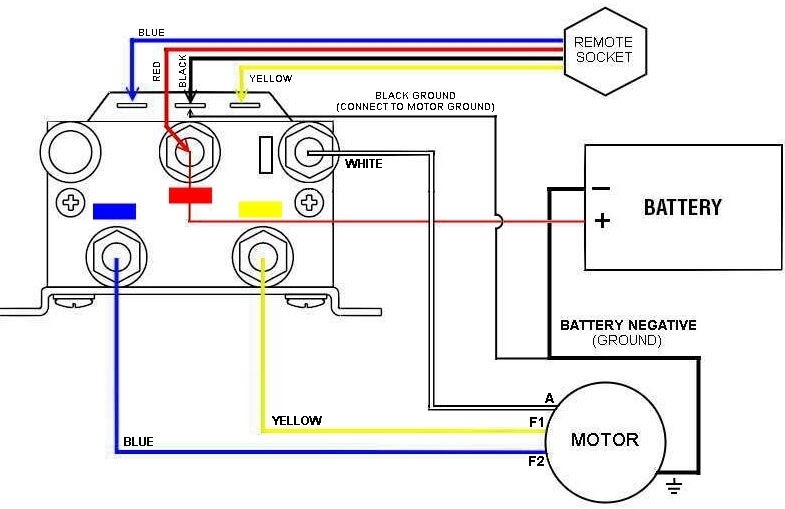
A Wiring Diagram Warn Winch Solenoid illustrates the electrical connections necessary to operate a Warn brand winch solenoid, a device that controls the flow of high-voltage current through an electric winch motor.
These diagrams are crucial for maintaining and troubleshooting winch systems, as they provide a clear visual representation of the wiring connections, including power sources, switches, fuses, and the winch motor. The ability to identify and locate specific components allows for efficient diagnosis and repair of electrical issues, preventing interruptions and ensuring safe winch operation.
The development of comprehensive wiring diagrams for Warn winches has contributed significantly to the ease of installation, maintenance, and troubleshooting of these systems. As winches have become increasingly complex, with the incorporation of various control features and accessories, proper wiring has become essential for maximizing their functionality and safety. These diagrams serve as valuable resources for winch enthusiasts, technicians, and installers, facilitating efficient and accurate electrical installations.
Understanding the various essential aspects of Wiring Diagram Warn Winch Solenoid is crucial for effectively creating informative content. These aspects provide a comprehensive overview of the topic, ensuring that all pertinent information is covered.
- Definition: A Wiring Diagram Warn Winch Solenoid is a technical document that illustrates the electrical connections necessary to operate a Warn winch solenoid.
- Purpose: The primary purpose of a wiring diagram is to guide the installation, maintenance, and troubleshooting of Warn winch systems.
- Components: Wiring diagrams typically include symbols and labels representing power sources, switches, fuses, the winch motor, and other electrical components.
- Symbols and Conventions: Wiring diagrams adhere to standardized symbols and conventions to ensure universal understanding.
- Troubleshooting: These diagrams are invaluable for diagnosing and resolving electrical issues within Warn winch systems.
- Safety: Accurate wiring is essential for the safe operation of Warn winches, as it prevents electrical hazards.
- Customization: Wiring diagrams can be customized to accommodate specific winch configurations and accessories.
- Availability: Wiring diagrams are typically provided by Warn in the product documentation or can be obtained from authorized dealers.
These essential aspects provide a solid foundation for comprehending the role and significance of Wiring Diagram Warn Winch Solenoid. They not only facilitate effective content creation but also enhance the understanding and application of these diagrams in real-world scenarios.
Definition
A Wiring Diagram Warn Winch Solenoid is a technical document that provides a detailed visual representation of the electrical connections required to operate a Warn winch solenoid. It serves as a comprehensive guide for technicians and installers, ensuring proper functionality and safe operation of the winch system. Understanding this definition is critical for comprehending the significance and applications of Wiring Diagram Warn Winch Solenoid.
The wiring diagram is an essential component of Wiring Diagram Warn Winch Solenoid. It outlines the necessary electrical connections between the winch solenoid, power source, switches, fuses, and winch motor. Accurate wiring is crucial for transmitting power efficiently and preventing electrical hazards. Without a clear understanding of the wiring diagram, improper connections could lead to malfunctions, damage to components, or safety risks.
In real-world applications, Wiring Diagram Warn Winch Solenoid plays a vital role in various industries and scenarios. For instance, in off-roading and recovery operations, a properly wired winch system ensures reliable operation in challenging conditions. In construction and industrial settings, winches are used for heavy lifting and material handling, where precise wiring is essential for safety and efficiency.
Understanding the relationship between “Definition: A Wiring Diagram Warn Winch Solenoid is a technical document that illustrates the electrical connections necessary to operate a Warn winch solenoid.” and “Wiring Diagram Warn Winch Solenoid” underscores the importance of accurate electrical connections in winch systems. It highlights the need for qualified technicians and adherence to industry standards to ensure safe and effective operation of these powerful machines.
Purpose
Within the context of Wiring Diagram Warn Winch Solenoid, the purpose of a wiring diagram takes on critical importance. It serves as a comprehensive guide for technicians, installers, and users to ensure the proper functioning and safety of Warn winch systems. A well-designed wiring diagram simplifies the process of installing, maintaining, and troubleshooting these winch systems, minimizing downtime and potential hazards.
- Installation: Wiring diagrams provide step-by-step instructions for connecting the winch solenoid to the power source, switches, fuses, and winch motor. By following the diagram, technicians can ensure that all electrical components are properly connected, minimizing the risk of incorrect wiring and potential damage to the system.
- Maintenance: Regular maintenance is crucial for the longevity and performance of Warn winch systems. Wiring diagrams enable technicians to quickly identify and access specific components for inspection, cleaning, or replacement. This proactive approach helps prevent unexpected failures and ensures optimal winch operation.
- Troubleshooting: When issues arise, wiring diagrams become invaluable troubleshooting tools. By systematically tracing the electrical connections, technicians can pinpoint the source of the problem, whether it’s a loose connection, faulty component, or electrical short. This efficient troubleshooting process minimizes downtime and ensures prompt restoration of winch functionality.
- Safety: Accurate wiring is paramount for the safe operation of Warn winch systems. Wiring diagrams help ensure that all electrical connections comply with industry standards and safety regulations. Proper wiring prevents electrical hazards, such as short circuits, fires, or electrical shocks, safeguarding both the user and the equipment.
In summary, the purpose of a wiring diagram for Warn winch solenoids extends beyond mere documentation. It plays a vital role in ensuring proper installation, maintenance, troubleshooting, and safety throughout the lifespan of the winch system. Understanding and adhering to the guidelines outlined in these diagrams is essential for reliable winch operation and the prevention of potential hazards.
Components
Within the context of Wiring Diagram Warn Winch Solenoid, the inclusion of specific components plays a crucial role in understanding the overall system and its functionality. Wiring diagrams for Warn winch solenoids typically incorporate symbols and labels representing essential electrical components, each serving a distinct purpose within the winch system. A clear comprehension of these components is vital for effective installation, maintenance, and troubleshooting.
The power source, typically a battery, provides the electrical energy necessary to operate the winch system. Switches allow the user to control the direction and operation of the winch, while fuses protect the electrical system from overcurrent and potential damage. The winch motor converts electrical energy into mechanical energy, enabling the winch to perform its lifting or pulling functions. Other electrical components, such as solenoids, contactors, and relays, facilitate the proper functioning of the winch system by controlling the flow of electricity.
Real-life examples of these components can be found in various applications where Warn winches are employed. In off-road recovery operations, the winch solenoid plays a critical role in engaging the winch motor, allowing the winch to exert its pulling force to extract a stuck vehicle. In industrial settings, the proper wiring of power sources, switches, and fuses ensures the safe and reliable operation of winches used for heavy lifting or material handling.
Understanding the components of Wiring Diagram Warn Winch Solenoid is not only essential for technicians and installers but also for end-users seeking to operate and maintain their winch systems safely and effectively. By recognizing the function and location of each component, users can perform basic troubleshooting, identify potential issues, and prevent costly repairs or downtime.
Symbols and Conventions
Within the context of Wiring Diagram Warn Winch Solenoid, symbols and conventions play a pivotal role in ensuring clear and concise communication of complex electrical connections. Standardized symbols represent various electrical components, while conventions govern the layout and arrangement of these symbols within the diagram. This universal language facilitates efficient comprehension and troubleshooting of winch systems, regardless of language or cultural differences.
- Graphical Representation: Wiring diagrams utilize universally recognized graphical symbols to represent electrical components such as batteries, switches, fuses, and the winch motor. These symbols simplify complex circuits, making them easy to visualize and interpret.
- Component Identification: Standardized symbols allow for quick identification of specific components within the wiring diagram. This is particularly useful for troubleshooting, as technicians can easily locate and isolate potential problem areas.
- Circuit Functionality: Conventions dictate the arrangement and connection of symbols to convey the flow of electricity through the circuit. This visual representation helps users understand the functionality of the winch system and identify potential issues.
- International Comprehension: By adhering to international standards, wiring diagrams transcend language barriers, ensuring effective communication among technicians and users worldwide.
In conclusion, standardized symbols and conventions form the foundation of Wiring Diagram Warn Winch Solenoid. They provide a common language for electrical schematics, enabling technicians and users to comprehend, troubleshoot, and maintain Warn winch systems efficiently and safely. This universal understanding contributes to the effective operation of winches in various industries and applications, ensuring reliable performance and safety.
Troubleshooting
Within the context of Wiring Diagram Warn Winch Solenoid, troubleshooting plays a critical role in maintaining optimal winch performance and safety. These diagrams provide a comprehensive roadmap for diagnosing and resolving electrical issues, minimizing downtime and ensuring reliable operation of Warn winch systems.
- Electrical Fault Isolation: Wiring diagrams enable technicians to isolate electrical faults efficiently. By systematically tracing the circuit connections, they can pinpoint the exact location of the problem, whether it’s a loose connection, faulty component, or electrical short.
- Component Testing: Troubleshooting diagrams guide technicians in testing individual components, such as switches, relays, and solenoids. This targeted approach allows for quick identification of malfunctioning components, reducing guesswork and minimizing repair time.
- Real-Life Applications: In real-world scenarios, wiring diagrams are indispensable for troubleshooting Warn winch systems in various applications. For instance, in off-road recovery situations, a faulty connection may prevent the winch from functioning properly, hindering vehicle extraction. Wiring diagrams empower technicians to diagnose and resolve such issues promptly, ensuring a successful recovery operation.
- Safety Implications: Accurate troubleshooting using wiring diagrams is crucial for maintaining the safety of Warn winch systems. Electrical faults, if left unattended, can lead to hazardous situations, such as electrical fires or shocks. Wiring diagrams guide technicians in identifying and rectifying these issues, ensuring safe operation and preventing potential accidents.
In conclusion, the troubleshooting aspect of Wiring Diagram Warn Winch Solenoid is of paramount importance in maintaining the functionality, reliability, and safety of Warn winch systems. These diagrams empower technicians with a systematic approach to diagnosing and resolving electrical issues, minimizing downtime, and ensuring the safe operation of winches in various applications.
Safety
In the context of Wiring Diagram Warn Winch Solenoid, accurate wiring forms the cornerstone of safety in operating Warn winch systems. It prevents electrical hazards that could lead to catastrophic consequences, ensuring the well-being of users and the integrity of equipment.
Electrical hazards, such as short circuits, fires, and electrical shocks, can arise from improper wiring practices. These hazards not only pose a safety risk to individuals but can also damage the winch system and surrounding components. By adhering to the guidelines outlined in Wiring Diagram Warn Winch Solenoid, technicians can ensure that all electrical connections are secure, properly insulated, and compliant with safety standards.
Real-life examples underscore the importance of accurate wiring in Warn winch systems. In off-road recovery situations, improper wiring can lead to electrical malfunctions, hindering the extraction of stranded vehicles and putting individuals at risk. Similarly, in industrial settings where winches are used for heavy lifting, faulty wiring can result in equipment damage, production delays, and potential safety incidents.
Understanding the connection between safety and accurate wiring in Wiring Diagram Warn Winch Solenoid is crucial for all stakeholders involved in the installation, maintenance, and operation of Warn winch systems. It empowers technicians with the knowledge and skills to ensure electrical safety, safeguarding users and preventing costly accidents.
In summary, Wiring Diagram Warn Winch Solenoid places paramount importance on safety by providing a roadmap for accurate wiring practices. By adhering to these guidelines, technicians can mitigate electrical hazards, ensuring the safe and reliable operation of Warn winch systems in diverse applications.
Customization
Wiring Diagram Warn Winch Solenoid is essential in understanding the customization of wiring diagrams to suit specific winch configurations and accessories. Customization plays a crucial role in ensuring optimal performance, versatility, and safety in various winch applications.
The ability to customize wiring diagrams allows for the integration of additional components and accessories, such as remote controls, wireless receivers, and auxiliary lighting. By incorporating these accessories, users can enhance the functionality and convenience of their winch systems. For instance, in off-roading scenarios, a customized wiring diagram can incorporate a wireless remote control, enabling the user to operate the winch from a safe distance while navigating challenging terrain.
Customization also addresses the unique electrical requirements of different winch configurations. For example, winches with synthetic ropes may require specific wiring modifications to accommodate their unique electrical characteristics. A customized wiring diagram ensures that the electrical system is optimized for the specific winch configuration, maximizing efficiency and preventing potential issues.
Understanding the connection between customization and Wiring Diagram Warn Winch Solenoid empowers users and technicians to tailor their winch systems to meet their specific needs and requirements. It enables them to integrate additional features, adapt to diverse winch configurations, and ensure safe and reliable operation in various applications.
Availability
In the realm of Wiring Diagram Warn Winch Solenoid, the aspect of availability plays a pivotal role in ensuring accessibility to these essential documents. This section aims to explore the various dimensions of the availability of wiring diagrams, highlighting their importance and implications.
- Manufacturer’s Documentation: Wiring diagrams are commonly included in the product documentation provided by Warn. These manuals accompany the winch system and offer detailed instructions, including wiring schematics. Having the wiring diagram readily available during installation, maintenance, or troubleshooting minimizes the risk of errors and ensures adherence to the manufacturer’s specifications.
- Authorized Dealers: For users who may have misplaced or require additional copies of wiring diagrams, authorized dealers serve as valuable resources. These dealers are equipped with up-to-date technical documentation and can provide original or replacement wiring diagrams specific to the winch model.
- Online Resources: The internet has become a vast repository of technical information, including wiring diagrams for Warn winches. Many manufacturers and online retailers make these diagrams available for download, allowing users to access them conveniently and store them digitally for future reference.
- Community Forums: Online forums dedicated to Warn winches and off-roading enthusiasts often share and discuss wiring diagrams. These communities provide a platform for users to exchange information, troubleshoot issues, and access a wealth of collective knowledge, including custom wiring configurations and modifications.
In conclusion, the availability of wiring diagrams, whether through manufacturer’s documentation, authorized dealers, online resources, or community forums, is crucial for the proper installation, maintenance, and troubleshooting of Warn winch systems. Easy access to accurate wiring diagrams empowers users with the necessary information to operate their winches safely, efficiently, and in accordance with the manufacturer’s guidelines.


Related Posts


