Wiring Diagram Symbols HVAC are standardized symbols used to represent various components and devices in heating, ventilation, and air conditioning (HVAC) systems. These graphical symbols simplify the depiction of complex wiring connections and system layouts, making it easier for engineers, technicians, and contractors to design, install, troubleshoot, and maintain HVAC systems. Each symbol represents a specific component, such as thermostats, compressors, fans, valves, switches, and sensors.
Wiring diagram symbols HVAC play a crucial role in ensuring accurate communication and understanding among professionals involved in HVAC projects. They provide a universal language that transcends language barriers and facilitates collaboration. The standardized symbols help reduce errors, improve system performance, and enhance overall safety. Historically, the development of HVAC wiring diagram symbols has been fueled by the need for efficient and reliable system design and maintenance. The symbols have evolved over time to reflect advancements in HVAC technology and industry best practices.
As we delve deeper into this article, we will explore the essential role of wiring diagram symbols HVAC in various aspects, including system design, installation, troubleshooting, and maintenance. We will also highlight specific examples and case studies to illustrate their practical applications.
Wiring diagram symbols HVAC play a fundamental role in the design, installation, maintenance, and troubleshooting of heating, ventilation, and air conditioning systems. Understanding the essential aspects of these symbols is critical for effective communication among engineers, technicians, and contractors involved in HVAC projects. Here are eight key aspects to consider:
- Standardization: Wiring diagram symbols HVAC are standardized to ensure consistency and clarity across different projects and organizations.
- Graphical Representation: Symbols provide a graphical representation of HVAC components, simplifying complex wiring connections and system layouts.
- Universal Language: Standardized symbols transcend language barriers, facilitating collaboration among professionals from diverse backgrounds.
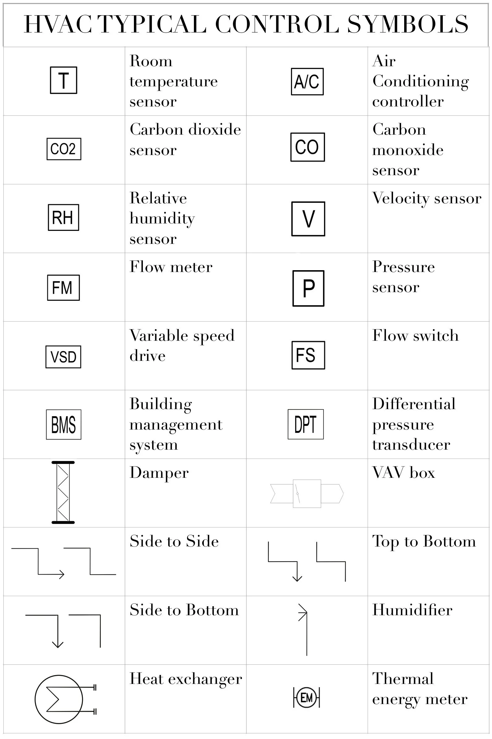
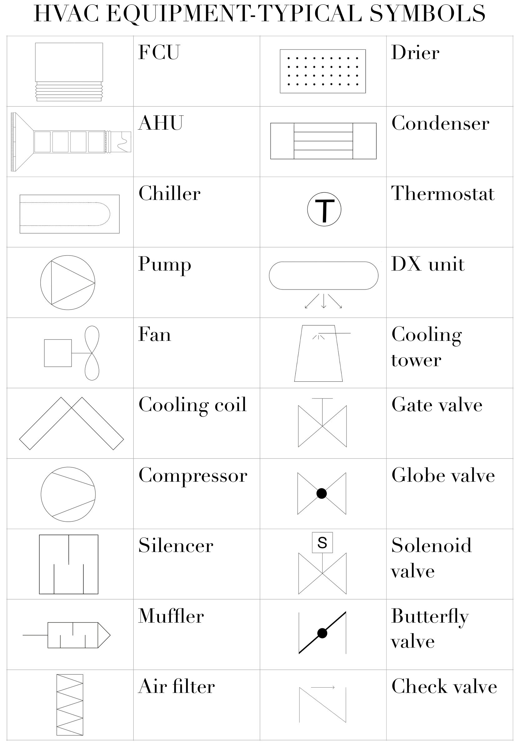
- Component Identification: Each symbol represents a specific HVAC component, such as thermostats, compressors, fans, valves, switches, and sensors.
- System Design: Symbols enable engineers to design HVAC systems efficiently and accurately, ensuring optimal performance and safety.
- Installation: Symbols guide technicians during installation, reducing errors and ensuring proper system operation.
- Troubleshooting: Symbols help technicians quickly identify and resolve system issues, minimizing downtime and maintenance costs.
- Maintenance: Symbols provide a visual reference for maintenance tasks, ensuring regular upkeep and extending system lifespan.
These aspects collectively contribute to the effective design, installation, operation, and maintenance of HVAC systems. Wiring diagram symbols HVAC serve as a universal language that enables professionals to communicate complex technical information concisely and accurately. They enhance collaboration, reduce errors, improve system performance, and promote safety in the HVAC industry.
Standardization
Within the realm of “Wiring Diagram Symbols Hvac”, the aspect of Standardization holds paramount importance, ensuring consistency and clarity in the design, installation, maintenance, and troubleshooting of HVAC systems. Standardization of HVAC wiring diagram symbols enables effective communication and collaboration among professionals, transcends language barriers, and promotes safety and efficiency.
- Universal Understanding: Standardized symbols provide a universal language that can be easily understood by engineers, technicians, and contractors from diverse backgrounds, facilitating seamless collaboration and knowledge sharing.
- Reduced Errors: Standardization minimizes the risk of errors during system design, installation, and maintenance. Consistent symbols ensure that everyone involved in the project is working from the same set of guidelines, reducing the likelihood of misinterpretation and costly mistakes.
- Improved System Performance: Accurate and consistent wiring diagrams are essential for optimal system performance. Standardized symbols ensure that all components are connected correctly, minimizing the potential for malfunctions and breakdowns.
- Enhanced Safety: Clear and unambiguous wiring diagrams are crucial for ensuring the safe operation of HVAC systems. Standardized symbols help identify potential hazards and ensure proper installation and maintenance practices, reducing the risk of electrical accidents and other safety concerns.
In summary, the Standardization of Wiring Diagram Symbols HVAC plays a vital role in promoting consistency, clarity, and safety in the design, installation, maintenance, and troubleshooting of HVAC systems. By providing a universal language and reducing the potential for errors, standardized symbols contribute to the efficient and reliable operation of HVAC systems in residential, commercial, and industrial settings.
Graphical Representation
Within the context of “Wiring Diagram Symbols Hvac”, the significance of graphical representation cannot be overstated. Wiring diagrams rely heavily on symbols to convey complex information in a simplified and visually comprehensible manner. These symbols serve as a graphical language, providing a clear representation of HVAC components, their connections, and the overall system layout.
The graphical representation offered by symbols is a critical component of “Wiring Diagram Symbols Hvac” for several reasons:
- Simplified Complexity: HVAC systems often involve numerous components and intricate wiring connections. Graphical symbols simplify this complexity by representing each component with a distinct symbol, making it easier to understand the system’s design and functionality.
- Enhanced Clarity: Symbols provide a clear and concise visual representation of the system layout. They eliminate the need for lengthy written descriptions, reducing the potential for misunderstandings and errors.
- Universal Understanding: Graphical symbols transcend language barriers, enabling professionals from diverse backgrounds to interpret and work with wiring diagrams effectively.
- Improved Troubleshooting: When troubleshooting HVAC systems, graphical symbols help technicians quickly identify the location and type of components, expediting the diagnostic process.
Real-life examples of graphical representation in “Wiring Diagram Symbols Hvac” include:
- Symbols for different types of HVAC equipment, such as compressors, fans, and thermostats.
- Symbols for electrical components, such as switches, relays, and transformers.
- Symbols for piping and ductwork, indicating the flow of air and refrigerants.
- Symbols for control systems, including sensors, actuators, and controllers.
Understanding the graphical representation of “Wiring Diagram Symbols Hvac” is essential for effectively designing, installing, maintaining, and troubleshooting HVAC systems. Graphical symbols provide a simplified and standardized visual language that enhances communication, reduces errors, and improves overall system performance.
Universal Language
Within the realm of “Wiring Diagram Symbols Hvac”, the aspect of “Universal Language” takes center stage, bridging communication gaps and facilitating seamless collaboration among professionals from diverse cultural and linguistic backgrounds. Standardized symbols transcend the limitations of language, enabling effective communication and knowledge sharing across borders.
- Global Collaboration: Standardized symbols enable engineers, technicians, and contractors from different countries to work together on HVAC projects without language barriers. This promotes global collaboration and the exchange of best practices, leading to innovative and efficient HVAC system designs.
- Simplified Training: Standardized symbols simplify training and onboarding for new professionals entering the HVAC industry. By eliminating the need for language-specific training materials, organizations can streamline the training process and ensure that all technicians have a common understanding of HVAC system designs.
- Reduced Errors: Universal symbols minimize the risk of errors during system installation and maintenance. When everyone involved in the project is working with the same set of symbols, the chances of misinterpretation and mistakes are significantly reduced.
- Enhanced Safety: Clear and consistent symbols are essential for ensuring the safe operation of HVAC systems. Standardized symbols help identify potential hazards and ensure proper installation and maintenance practices, reducing the risk of accidents and injuries.
In summary, the “Universal Language” aspect of “Wiring Diagram Symbols Hvac” is a cornerstone of effective communication and collaboration in the HVAC industry. Standardized symbols transcend language barriers, simplify training, reduce errors, and enhance safety, ensuring that HVAC systems are designed, installed, and maintained to the highest standards globally.
Component Identification
Within the context of “Wiring Diagram Symbols Hvac”, the aspect of “Component Identification” plays a pivotal role in ensuring accurate and efficient system design, installation, and maintenance. Each symbol represents a specific HVAC component, providing a standardized visual representation that simplifies complex wiring diagrams and facilitates effective communication among professionals.
The significance of “Component Identification” within “Wiring Diagram Symbols Hvac” stems from its ability to:
- Simplify System Design: By representing each component with a unique symbol, wiring diagrams become easier to interpret and comprehend, enabling engineers to design HVAC systems efficiently and accurately.
- Enhance Installation Accuracy: During installation, technicians can quickly identify the correct components and their connections using the standardized symbols, reducing the risk of errors and ensuring proper system operation.
- Expedite Troubleshooting: When troubleshooting HVAC systems, technicians can use the symbols to quickly locate and identify faulty components, expediting the diagnostic and repair process.
- Promote Maintenance Efficiency: Regular maintenance is crucial for ensuring optimal HVAC performance. Component identification through symbols enables technicians to easily identify and access components for inspection, cleaning, or replacement.
Real-life examples of “Component Identification” within “Wiring Diagram Symbols Hvac” include:
- A symbol for a thermostat indicates the location and type of temperature control device.
- A symbol for a compressor represents the unit responsible for compressing refrigerant gas.
- A symbol for a fan indicates the location and type of air-circulating device.
- A symbol for a valve represents the device used to control the flow of fluids.
Understanding the “Component Identification” aspect of “Wiring Diagram Symbols Hvac” is essential for effectively designing, installing, maintaining, and troubleshooting HVAC systems. By providing a standardized visual representation of each component, these symbols enhance communication, reduce errors, improve system performance, and promote safety in the HVAC industry.
System Design
Within the realm of “Wiring Diagram Symbols Hvac”, the significance of “System Design” cannot be overstated. Wiring diagrams play a crucial role in the efficient and accurate design of HVAC systems, ensuring optimal performance and safety. The standardized symbols used in these diagrams provide a visual representation of the system’s components and their interconnections, enabling engineers to create designs that meet specific requirements and industry standards.
The relationship between “System Design” and “Wiring Diagram Symbols Hvac” is one of cause and effect. Wiring diagrams are an essential tool for engineers during the system design process. By using standardized symbols, engineers can quickly and accurately represent the system’s layout, component selection, and control strategies. This visual representation facilitates collaboration, reduces errors, and ensures that the system meets the desired specifications.
Real-life examples of “System Design” within “Wiring Diagram Symbols Hvac” include:
- Using symbols to represent different types of HVAC equipment, such as air handlers, chillers, and boilers.
- Using symbols to indicate the flow of air and refrigerant throughout the system.
- Using symbols to represent control devices, such as thermostats, sensors, and actuators.
Understanding the connection between “System Design” and “Wiring Diagram Symbols Hvac” is essential for HVAC engineers and technicians. By leveraging standardized symbols, engineers can design HVAC systems that are efficient, reliable, and safe. These symbols provide a common language for communication and documentation, ensuring that all stakeholders involved in the design, installation, and maintenance of HVAC systems have a clear understanding of the system’s operation.
In summary, “Wiring Diagram Symbols Hvac” are a critical component of “System Design,” enabling engineers to create HVAC systems that meet specific requirements and industry standards. The use of standardized symbols promotes efficiency, accuracy, and safety throughout the system design process.
Installation
Within the realm of “Wiring Diagram Symbols Hvac”, the aspect of “Installation” plays a pivotal role in ensuring the successful and efficient operation of HVAC systems. Wiring diagrams, with their standardized symbols, serve as a guiding light for technicians during the installation process, helping to minimize errors and guarantee proper system functionality.
- Clarity and Precision: Wiring diagrams provide a clear and precise representation of the system’s components and their interconnections. This visual representation enables technicians to understand the intended design and make informed decisions during installation, reducing the likelihood of errors.
- Component Identification: Wiring diagrams use standardized symbols to represent specific HVAC components, such as thermostats, compressors, and fans. This unambiguous identification helps technicians quickly locate and connect the correct components, ensuring proper system operation.
- Error Reduction: By following the standardized symbols in wiring diagrams, technicians can minimize errors during installation. The visual representation of the system’s connections reduces the risk of incorrect wiring, which could lead to system malfunctions or safety hazards.
- Safety Assurance: Accurate wiring is crucial for the safe operation of HVAC systems. Wiring diagrams, with their standardized symbols, help ensure that electrical connections are made correctly, reducing the risk of electrical accidents or fires.
In summary, “Installation: Symbols guide technicians during installation, reducing errors and ensuring proper system operation.” is a critical aspect of “Wiring Diagram Symbols Hvac”. By providing a clear visual representation of the system’s components and interconnections, wiring diagrams empower technicians to install HVAC systems accurately and efficiently, minimizing errors, ensuring proper operation, and promoting safety.
Troubleshooting
The connection between “Troubleshooting: Symbols help technicians quickly identify and resolve system issues, minimizing downtime and maintenance costs.” and “Wiring Diagram Symbols Hvac” is one of cause and effect. Wiring diagrams, with their standardized symbols, provide a visual representation of the system’s components and their interconnections. This enables technicians to quickly identify and resolve system issues, minimizing downtime and maintenance costs.
Real-life examples of “Troubleshooting: Symbols help technicians quickly identify and resolve system issues, minimizing downtime and maintenance costs.” within “Wiring Diagram Symbols Hvac” include:
- Using wiring diagrams to identify a faulty component, such as a malfunctioning thermostat or a clogged filter.
- Using wiring diagrams to trace the path of refrigerant flow to identify a leak or blockage.
- Using wiring diagrams to troubleshoot electrical problems, such as a tripped circuit breaker or a loose connection.
Understanding the connection between “Troubleshooting: Symbols help technicians quickly identify and resolve system issues, minimizing downtime and maintenance costs.” and “Wiring Diagram Symbols Hvac” is critical for HVAC technicians. By leveraging standardized symbols, technicians can quickly and accurately diagnose and resolve system issues, reducing downtime and maintenance costs. This understanding also promotes safety by ensuring that systems are operating correctly and efficiently.
In summary, wiring diagram symbols are essential for effective troubleshooting of HVAC systems. By providing a visual representation of the system’s components and interconnections, these symbols enable technicians to quickly identify and resolve system issues, minimizing downtime and maintenance costs. This understanding is critical for ensuring the efficient and safe operation of HVAC systems.
Maintenance
The connection between “Maintenance: Symbols provide a visual reference for maintenance tasks, ensuring regular upkeep and extending system lifespan.” and “Wiring Diagram Symbols Hvac” is one of cause and effect. Wiring diagrams, with their standardized symbols, provide a visual representation of the system’s components and their interconnections. This enables technicians to easily identify and access components for inspection, cleaning, or replacement, ensuring regular upkeep and extending the system’s lifespan.
Real-life examples of “Maintenance: Symbols provide a visual reference for maintenance tasks, ensuring regular upkeep and extending system lifespan.” within “Wiring Diagram Symbols Hvac” include:
- Using wiring diagrams to identify and clean dirty condenser coils, improving system efficiency and extending its lifespan.
- Using wiring diagrams to locate and replace worn-out fan belts, preventing overheating and potential system damage.
- Using wiring diagrams to troubleshoot and repair electrical faults, ensuring safe and reliable system operation.
Understanding the connection between “Maintenance: Symbols provide a visual reference for maintenance tasks, ensuring regular upkeep and extending system lifespan.” and “Wiring Diagram Symbols Hvac” is critical for HVAC technicians and maintenance personnel. By leveraging standardized symbols, technicians can effectively maintain and service HVAC systems, minimizing downtime and extending their lifespan. This understanding also promotes safety by ensuring that systems are operating correctly and efficiently.
In summary, wiring diagram symbols are essential for effective maintenance of HVAC systems. By providing a visual representation of the system’s components and interconnections, these symbols enable technicians to easily identify and access components for inspection, cleaning, or replacement, ensuring regular upkeep and extending the system’s lifespan. This understanding is critical for ensuring the efficient and safe operation of HVAC systems.


Related Posts


