A Wiring Diagram for John Deere L110 is a detailed plan that outlines the electrical system of the mower, including the locations of all wires, components, and connections. It serves as a visual guide to assist in troubleshooting electrical problems, tracing wire paths, and identifying faulty components.
The wiring diagram is crucial for maintenance and repair, as it provides a comprehensive overview of the mower’s electrical system. Its benefits include simplifying electrical diagnostics, reducing repair time, and enhancing technician productivity.
A key historical development in wiring diagrams was the introduction of computer-aided design (CAD) software, which has significantly improved their accuracy, clarity, and ease of use.
A wiring diagram for John Deere L110 is paramount for comprehending and maintaining the mower’s electrical system. These essential aspects provide a comprehensive understanding of the diagram, facilitating effective troubleshooting and repair:
- Components: Depicts all electrical components, their locations, and interconnections.
- Connections: Specifies how components are electrically connected, including wire colors and terminal designations.
- Grounding points: Indicates where electrical components are grounded to the mower’s frame.
- Wire colors and gauges: Identifies the color coding and thickness of wires, aiding in wire tracing and replacement.
- Fuse and relay locations: Pinpoints the positions of fuses and relays, enabling easy access for inspection and replacement.
- Circuit protection: Outlines the protective measures implemented to safeguard electrical components from damage due to overcurrent or short circuits.
- Troubleshooting guide: Provides a step-by-step approach to diagnosing and resolving electrical issues.
- Safety precautions: Emphasizes essential safety measures to adhere to when working with the mower’s electrical system.
- Legend and symbols: Explains the symbols and notations used throughout the diagram, ensuring proper interpretation.
These aspects collectively empower technicians and enthusiasts to efficiently diagnose and repair electrical problems, ensuring optimal mower performance and safety.
Components
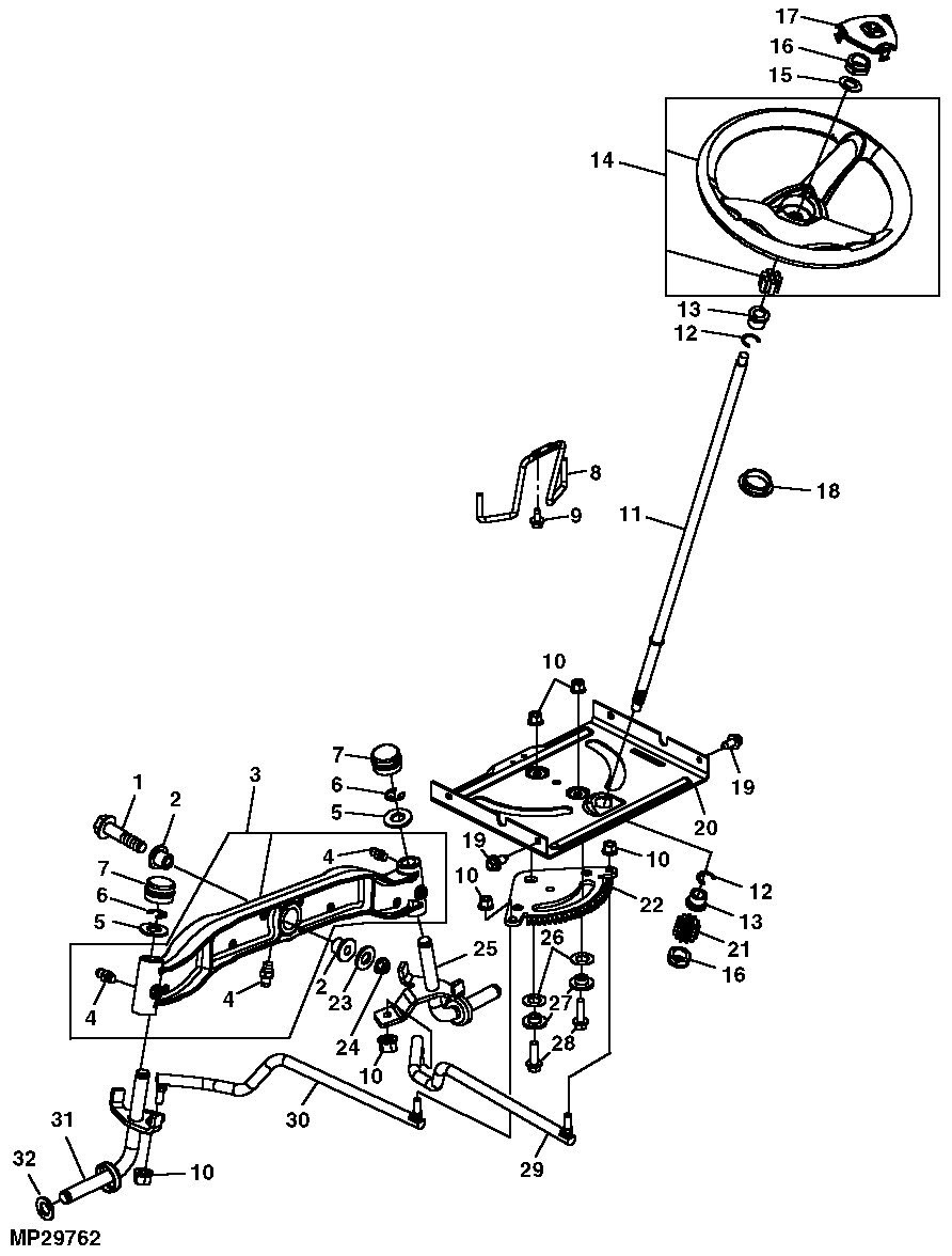
The section “Components: Depicts all electrical components, their locations, and interconnections” within a Wiring Diagram for John Deere L110 plays a pivotal role in understanding and troubleshooting the mower’s electrical system.
This section provides a comprehensive overview of all electrical components used in the mower, including their precise locations and how they are interconnected. It serves as a visual guide, enabling technicians and enthusiasts to quickly identify and locate specific components within the complex electrical system.
Real-life examples of components depicted in a Wiring Diagram for John Deere L110 include the battery, starter motor, alternator, ignition switch, and various sensors. The diagram also illustrates how these components are interconnected via wires and connectors, forming a functional electrical circuit.
Understanding the components and their interconnections is crucial for effective troubleshooting. By tracing the flow of electricity through the diagram, technicians can pinpoint the source of electrical problems, such as a faulty component or a loose connection. This understanding empowers them to make informed decisions and implement appropriate repairs, ensuring optimal mower performance.
In summary, the section “Components: Depicts all electrical components, their locations, and interconnections” is an essential part of a Wiring Diagram for John Deere L110. It provides a visual representation of the mower’s electrical system, enabling technicians and enthusiasts to comprehend, diagnose, and repair electrical issues efficiently.
Connections
Within a Wiring Diagram for John Deere L110, the section titled “Connections: Specifies how components are electrically connected, including wire colors and terminal designations” holds paramount importance in understanding and troubleshooting the mower’s electrical system.
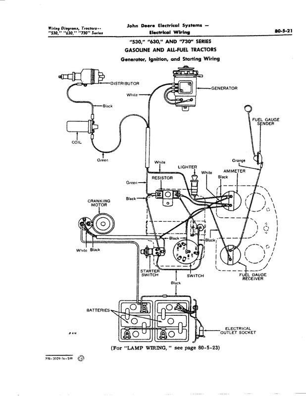
This section serves as a roadmap, detailing how various electrical components within the mower are interconnected via wires and connectors. It provides precise information on wire colors and terminal designations, enabling technicians and enthusiasts to trace the flow of electricity throughout the system.
Understanding the connections between components is crucial for effective troubleshooting and repair. By examining the diagram, technicians can identify any breaks or faults in the electrical circuit, such as loose connections or damaged wires. This knowledge empowers them to make informed decisions and implement appropriate repairs, ensuring optimal mower performance and safety.
Real-life examples of connections depicted in a Wiring Diagram for John Deere L110 include the connection between the battery and the starter motor, the connection between the ignition switch and the spark plug, and the connection between the alternator and the voltage regulator. The diagram also specifies the color coding and terminal designations for each wire, enabling technicians to easily identify and trace them throughout the system.
In summary, the section “Connections: Specifies how components are electrically connected, including wire colors and terminal designations” is a vital component of a Wiring Diagram for John Deere L110. It provides a clear understanding of how electrical components are interconnected, empowering technicians and enthusiasts to diagnose and repair electrical issues efficiently, ensuring the mower operates at its peak performance.
Grounding points
Grounding points, as indicated in a Wiring Diagram for John Deere L110, play a crucial role in ensuring the proper functioning and safety of the mower’s electrical system. Grounding refers to the electrical connection between an electrical circuit and the metal frame or chassis of the mower. This connection provides a common reference point for electrical current, ensuring that all electrical components operate at the same electrical potential and preventing dangerous voltage spikes.
- Safety: Grounding provides a safe path for electrical current to flow in the event of a fault or short circuit, preventing the buildup of excessive voltage on the mower’s frame. This helps protect the operator from electrical shock and prevents damage to electrical components.
- Electrical Stability: Grounding creates a stable electrical reference point, ensuring that all electrical components operate at the same voltage level. This stability helps prevent erratic behavior, premature component failure, and interference with sensitive electronic systems.
- Component Protection: Grounding helps protect electrical components from damage due to voltage spikes or surges. By providing a low-resistance path to ground, grounding diverts excess electrical current away from sensitive components, preventing burnout or damage.
- Noise Reduction: Grounding helps reduce electrical noise and interference in the electrical system. By providing a common reference point for electrical current, grounding prevents stray currents from flowing through unintended paths, which can cause noise and interference in electronic systems.
Understanding the grounding points indicated in a Wiring Diagram for John Deere L110 is essential for proper troubleshooting and maintenance. By ensuring that all electrical components are properly grounded, technicians can prevent electrical problems, improve system reliability, and enhance the overall safety of the mower.
Wire colors and gauges
Within a Wiring Diagram for John Deere L110, the section “Wire colors and gauges: Identifies the color coding and thickness of wires, aiding in wire tracing and replacement” plays a crucial role in understanding and troubleshooting the mower’s electrical system. This section provides essential information about the color coding and thickness (gauge) of wires used throughout the system, enabling technicians and enthusiasts to easily identify, trace, and replace wires as needed.
Color coding is a standardized practice used to identify the function or purpose of wires in an electrical system. Each wire is assigned a specific color, making it easier to trace the flow of electricity through the system and identify which components are connected to each wire. Understanding the color coding scheme is crucial for accurate troubleshooting and repairs.
Wire gauge refers to the thickness of the wire, which determines its current-carrying capacity. Thicker wires can carry more current than thinner wires, and the appropriate gauge of wire must be used for each application to ensure safe and reliable operation of the electrical system.
Real-life examples of wire colors and gauges within a Wiring Diagram for John Deere L110 include:
- Red wires are typically used for power supply lines, connecting the battery to various electrical components.
- Black wires are commonly used for ground connections, providing a path for electrical current to return to the battery.
- Green wires are often used for safety-related circuits, such as the engine kill switch or the PTO (power take-off) circuit.
- Yellow wires may be used for charging circuits, such as the alternator output wire.
- Blue wires are sometimes used for lighting circuits, such as the headlights or taillights.
Understanding the wire colors and gauges indicated in a Wiring Diagram for John Deere L110 is essential for proper troubleshooting, maintenance, and repair of the mower’s electrical system. By accurately identifying and tracing wires, technicians can quickly diagnose electrical problems, replace faulty wires, and ensure the safe and reliable operation of the mower.
Fuse and relay locations
Within the comprehensive Wiring Diagram for John Deere L110, the section titled “Fuse and relay locations: Pinpoints the positions of fuses and relays, enabling easy access for inspection and replacement” holds significant importance in ensuring the mower’s electrical system operates safely and efficiently.
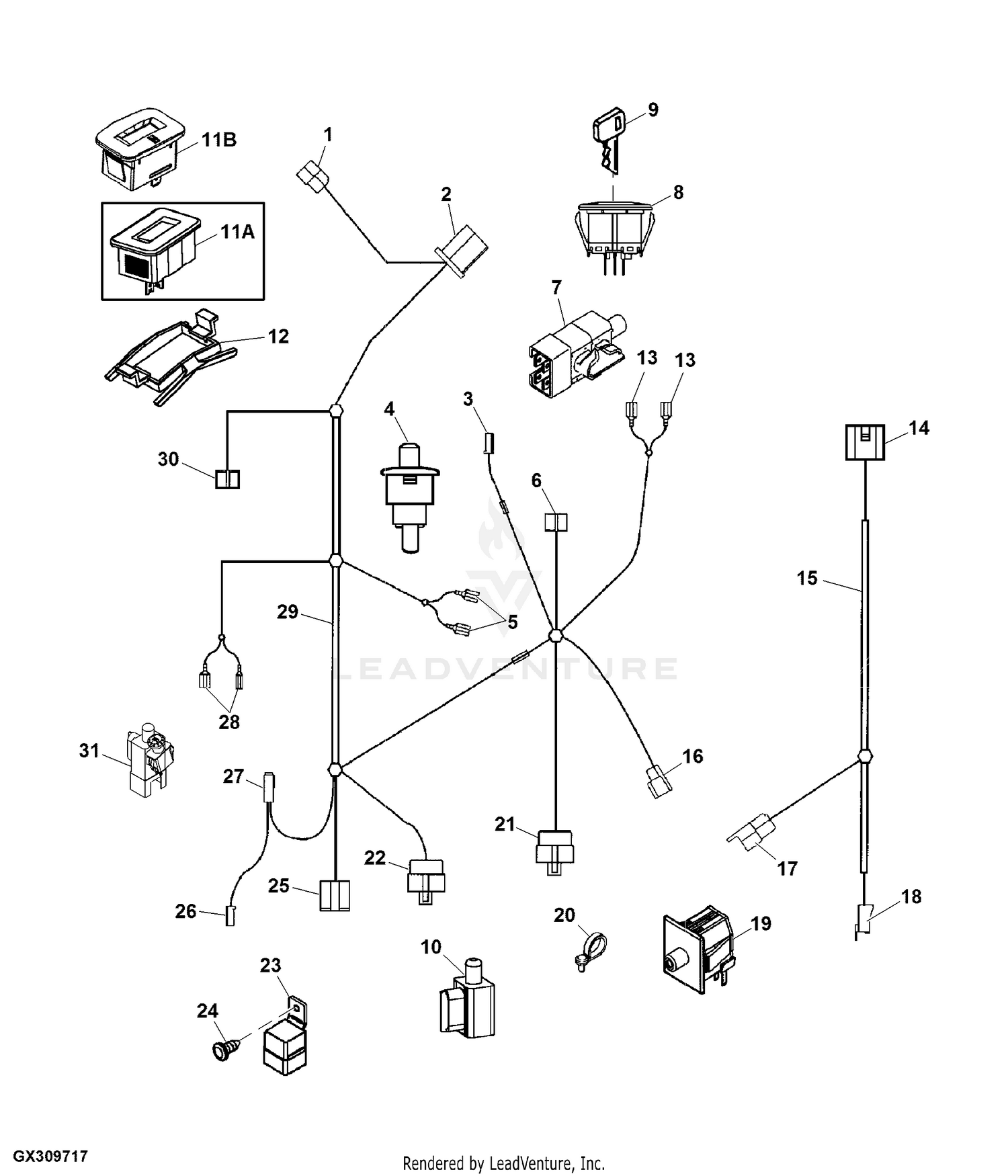
- Identification: This section clearly identifies the locations of all fuses and relays within the mower’s electrical system. Fuses protect electrical circuits from damage due to overcurrent conditions, while relays act as switches, controlling the flow of electricity to various components.
- Accessibility: The diagram ensures that fuses and relays are positioned in easily accessible locations, allowing for quick and convenient inspection, testing, and replacement if necessary. This accessibility minimizes downtime and simplifies maintenance procedures.
- Circuit protection: By precisely indicating the amperage rating of each fuse, the diagram enables technicians to select and install the correct replacement fuses, ensuring adequate protection for electrical circuits and components.
- Troubleshooting: The diagram serves as a valuable tool for troubleshooting electrical issues. By identifying the location of fuses and relays, technicians can quickly isolate potential problem areas, reducing diagnostic time and expediting repairs.
Overall, the section “Fuse and relay locations: Pinpoints the positions of fuses and relays, enabling easy access for inspection and replacement” is a critical component of the Wiring Diagram for John Deere L110. It empowers technicians and enthusiasts to maintain, diagnose, and repair the mower’s electrical system with confidence, ensuring optimal performance and safety.
Circuit protection
Within the context of a Wiring Diagram for John Deere L110, the section “Circuit protection: Outlines the protective measures implemented to safeguard electrical components from damage due to overcurrent or short circuits” assumes critical importance in understanding and maintaining the mower’s electrical system. This section serves as a guide to the various protective measures employed to shield electrical components from damage caused by excessive current flow or short circuits.
Protection against overcurrent and short circuits is essential to ensure the safety and longevity of the mower’s electrical system. Overcurrent conditions can arise due to electrical faults, overloading, or other abnormal situations, leading to excessive current flow through electrical components. Short circuits, on the other hand, occur when an unintended path of low resistance is created between two points in the electrical system, causing a sudden surge of current. Both overcurrent and short circuits can cause damage to electrical components, wiring, and other parts of the mower.
The Wiring Diagram for John Deere L110 provides detailed information on the protective measures implemented to safeguard against overcurrent and short circuits. These measures include the use of fuses, circuit breakers, and other protective devices. Fuses are designed to break the circuit when the current exceeds a predetermined safe level, preventing damage to downstream components. Circuit breakers perform a similar function but can be manually reset after the fault is cleared.
Understanding circuit protection is crucial for effective troubleshooting and maintenance of the mower’s electrical system. By identifying the location and function of protective devices, technicians can quickly isolate and address electrical faults, minimizing downtime and preventing more severe damage. Real-life examples of circuit protection within a Wiring Diagram for John Deere L110 include the use of fuses to protect the ignition circuit and circuit breakers to safeguard the charging system.
In summary, the section “Circuit protection: Outlines the protective measures implemented to safeguard electrical components from damage due to overcurrent or short circuits” is a vital component of a Wiring Diagram for John Deere L110. It provides valuable information on the protective measures employed to ensure the safety and reliability of the mower’s electrical system, enabling technicians and enthusiasts to maintain, diagnose, and repair electrical issues efficiently.
Troubleshooting guide
Within the context of a Wiring Diagram for John Deere L110, the section “Troubleshooting guide: Provides a step-by-step approach to diagnosing and resolving electrical issues” serves as an invaluable resource for technicians and enthusiasts seeking to maintain and repair the mower’s electrical system. This section offers a structured and methodical approach to identifying, diagnosing, and resolving electrical faults, empowering individuals to address electrical problems with confidence and efficiency.
The troubleshooting guide is a critical component of the Wiring Diagram for John Deere L110 as it provides a logical and sequential framework for diagnosing electrical issues. It guides users through a series of steps, beginning with identifying symptoms and systematically eliminating potential causes until the root of the problem is discovered. By following the troubleshooting guide, technicians can isolate electrical faults to specific components or circuits, enabling targeted repairs and minimizing downtime.
Real-life examples of the troubleshooting guide’s application within the Wiring Diagram for John Deere L110 include:
- Diagnosing a no-start condition by checking the battery voltage, starter motor connections, and safety switches.
- Troubleshooting a charging system issue by verifying the alternator output, voltage regulator function, and wiring integrity.
- Resolving lighting problems by identifying faulty bulbs, switches, or wiring harnesses.
Understanding the troubleshooting guide and its application is essential for effective electrical system maintenance and repair. By utilizing the step-by-step approach outlined in the guide, technicians can systematically identify and resolve electrical issues, ensuring the mower operates safely and efficiently. This understanding empowers individuals to perform basic electrical repairs, reduce repair costs, and extend the lifespan of their John Deere L110 mower.
In summary, the troubleshooting guide within the Wiring Diagram for John Deere L110 provides a valuable tool for diagnosing and resolving electrical problems. It offers a structured and logical approach to identifying and addressing electrical faults, empowering technicians and enthusiasts to maintain and repair the mower’s electrical system with confidence and precision.
Safety precautions
Within the comprehensive Wiring Diagram for John Deere L110, the section titled “Safety precautions: Emphasizes essential safety measures to adhere to when working with the mower’s electrical system” assumes paramount importance, providing indispensable guidance to ensure the safety of individuals performing electrical maintenance or repairs on the mower.
- Disconnect the battery: Before commencing any electrical work, it is imperative to disconnect the battery’s negative terminal. This crucial step eliminates the risk of electrical shock and prevents potential damage to electrical components due to accidental short circuits.
- Use insulated tools: When working with electrical components, it is essential to utilize insulated tools specifically designed for electrical applications. Insulated tools provide a protective barrier against electrical current, minimizing the risk of shock or injury.
- Wear appropriate attire: When performing electrical work, individuals should wear appropriate attire, including long pants, a long-sleeved shirt, safety glasses, and closed-toe shoes. This attire helps protect against potential burns or injuries in the event of an electrical incident.
- Avoid working in wet conditions: Water and electricity do not mix. It is crucial to avoid working on the mower’s electrical system in wet or damp conditions, as this significantly increases the risk of electrical shock.
Adhering to the safety precautions outlined in the Wiring Diagram for John Deere L110 is not only essential for personal safety but also for the protection of the mower’s electrical system. By following these guidelines, individuals can confidently perform electrical maintenance or repairs, minimizing the risk of accidents and ensuring the continued safe operation of the mower.
Legend and symbols
Within the context of “Wiring Diagram John Deere L110”, the section titled “Legend and symbols: Explains the symbols and notations used throughout the diagram, ensuring proper interpretation” holds immense significance, providing a comprehensive guide to understanding the various symbols and notations employed in the diagram. These symbols and notations serve as a visual language, enabling users to decipher the complex electrical system of the mower and perform maintenance or troubleshooting tasks with accuracy and efficiency.
- Electrical Components: The legend typically includes symbols representing various electrical components, such as batteries, resistors, switches, and motors. These symbols provide a standardized way to identify and locate specific components within the diagram.
- Wire Connections: Symbols are used to denote different types of wire connections, such as splices, terminals, and ground connections. Understanding these symbols is crucial for tracing the flow of electricity through the circuit.
- Color Coding: The legend often explains the color coding scheme used for wires in the diagram. Color coding helps in identifying the function or purpose of each wire, simplifying the process of wire tracing and troubleshooting.
- Troubleshooting Symbols: Some diagrams include symbols specifically designed to assist in troubleshooting electrical issues. These symbols may indicate test points, measurement points, or potential failure points.
The accurate interpretation of symbols and notations in a Wiring Diagram John Deere L110 is essential for effective electrical system maintenance and repair. By understanding the visual language of electrical diagrams, technicians and enthusiasts can confidently navigate the complexities of the mower’s electrical system, diagnose problems, and implement appropriate solutions, ensuring the safe and efficient operation of the mower.


Related Posts


