A Wiring Diagram GY6 is a visual representation of the electrical connections between various components within a GY6 engine, commonly found in scooters and other small motorized vehicles. It depicts the flow of electricity through wires, switches, sensors, and other electrical components, providing a clear understanding of the system’s functionality.
Wiring Diagrams are crucial for troubleshooting electrical issues, ensuring proper installation, and understanding the overall operation of the electrical system. They simplify the complex network of wires by presenting them in an organized and comprehensible format. Notably, the advent of computer-aided design (CAD) software has revolutionized the creation and distribution of Wiring Diagrams, making them more accurate and accessible.
This article delves into the intricacies of Wiring Diagrams GY6, exploring their composition, interpretation, and applications. With a thorough understanding of these diagrams, readers can effectively diagnose and repair electrical problems, optimize performance, and delve deeper into the inner workings of their GY6 engine.
Wiring Diagrams GY6 are essential tools for understanding, troubleshooting, and maintaining the electrical systems of GY6 engines. They provide a visual representation of the electrical connections between various components, making it easier to identify and resolve electrical issues.
- Components: Depicts the electrical components connected within the GY6 engine, such as the battery, ignition coil, and sensors.
- Connections: Illustrates the paths of electrical current flow through wires and connectors.
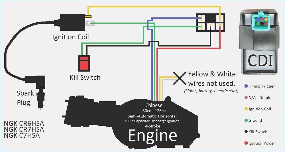
- Color Coding: Uses standardized color codes to identify different types of wires, simplifying tracing and troubleshooting.
- Symbols: Employs electrical symbols to represent components and connections, providing a universal language for understanding.
- Testing Points: Indicates locations for electrical testing, aiding in fault diagnosis.
- Troubleshooting: Guides users through the process of identifying and resolving electrical problems.
- Installation: Provides a roadmap for proper installation of electrical components.
- Maintenance: Facilitates regular maintenance tasks, such as wire inspection and connector cleaning.
- Modifications: Supports modifications to the electrical system, such as adding accessories or performance upgrades.
- Safety: Ensures electrical safety by providing a clear understanding of the system’s operation.
These aspects are interconnected and essential for effective use of Wiring Diagrams GY6. They enable technicians, enthusiasts, and DIYers to confidently diagnose, repair, modify, and maintain the electrical systems of their GY6 engines, ensuring optimal performance and safe operation.
Components
In the context of a Wiring Diagram GY6, the depiction of electrical components is a critical aspect that underpins the diagram’s functionality and utility. These components, such as the battery, ignition coil, and sensors, form the building blocks of the GY6 engine’s electrical system and play crucial roles in its operation.
The Wiring Diagram GY6 serves as a roadmap, visually representing the connections between these components and providing insights into the flow of electricity within the system. By accurately depicting the components and their interconnections, the diagram enables users to understand how the electrical system functions, identify potential issues, and perform troubleshooting and maintenance tasks.
Real-life examples of the components depicted in a Wiring Diagram GY6 include the battery, which provides electrical power to the system; the ignition coil, which generates the high-voltage spark required for ignition; and various sensors, such as the crankshaft position sensor and throttle position sensor, which provide feedback to the engine’s electronic control unit (ECU) for optimal performance. Understanding the location and function of these components is essential for effectively using the Wiring Diagram GY6 for troubleshooting, repair, and modification purposes.
In summary, the depiction of electrical components in a Wiring Diagram GY6 is a vital element that enables users to comprehend the structure and operation of the GY6 engine’s electrical system. By providing a visual representation of the components and their connections, the diagram empowers users to diagnose problems, perform maintenance, and make informed modifications, ensuring the optimal performance and safe operation of their GY6 engine.
Connections
In the context of Wiring Diagrams GY6, the depiction of connections plays a crucial role in understanding the flow of electricity within the GY6 engine’s electrical system. These connections, represented by wires and connectors, serve as pathways for electrical current to travel between various components, enabling the proper functioning of the engine.
- Wire Types and Color Coding: Wiring Diagrams GY6 utilize standardized color coding to identify different types of wires, such as power wires, ground wires, and signal wires. This color coding simplifies the tracing of wires and aids in troubleshooting.
- Connectors and Terminals: Connectors and terminals facilitate electrical connections between wires and components. The diagram depicts the types of connectors used, such as bullet connectors, spade connectors, and multi-pin connectors, along with their respective terminal arrangements.
- Signal Flow: Wiring Diagrams GY6 illustrate the flow of electrical signals through the system. This includes the paths taken by signals from sensors to the ECU and the transmission of control signals from the ECU to actuators.
- Grounding: Proper grounding is essential for the electrical system’s functionality and safety. The diagram indicates the grounding points and the paths taken by ground wires to complete electrical circuits.
By providing a clear representation of these connections, Wiring Diagrams GY6 empower users to understand the electrical system’s architecture, diagnose faults, and perform maintenance and repair tasks. The insights gained from the diagram’s depiction of connections contribute to the safe and optimal operation of the GY6 engine.
Color Coding
In the context of Wiring Diagrams GY6, color coding plays a critical role in simplifying the tracing and troubleshooting of electrical issues. The use of standardized color codes for different types of wires enables technicians and DIYers to quickly identify the purpose and function of each wire, reducing the time and effort required for electrical system diagnostics and repairs.
This color coding system is a vital component of Wiring Diagrams GY6 as it provides a consistent and universally understood language for representing electrical connections. By adhering to established color coding conventions, Wiring Diagrams GY6 ensure that users can easily interpret and navigate the diagram, regardless of their experience level or familiarity with the specific GY6 engine model.
Real-life examples of color coding within Wiring Diagrams GY6 include:
Red wires typically represent positive power connections, carrying voltage from the battery to various components. Black wires are commonly used for ground connections, providing a pathway for electrical current to return to the battery. Blue wires often indicate connections to sensors, transmitting data and signals to the engine’s electronic control unit (ECU). Yellow wires are frequently used for lighting circuits, powering headlights, taillights, and other illumination components.
Practical applications of understanding color coding in Wiring Diagrams GY6 extend to various electrical tasks, such as:
Tracing wire paths to identify open circuits, shorts, or other faults. Troubleshooting electrical issues by isolating specific circuits or components. Modifying or adding electrical accessories to the GY6 engine. Ensuring proper electrical connections during engine maintenance or repairs.
In summary, color coding in Wiring Diagrams GY6 is an essential element that streamlines electrical system troubleshooting and maintenance. By using standardized color codes to identify different types of wires, these diagrams provide a clear and intuitive visual representation of the GY6 engine’s electrical system, empowering users to confidently diagnose and resolve electrical issues, and optimize engine performance.
Symbols
Within the context of Wiring Diagram Gy6, symbols form the cornerstone of communication, enabling technicians and enthusiasts to decipher the intricacies of the GY6 engine’s electrical system. These symbols, adhering to standardized conventions, provide a universal language that transcends language barriers and Erfahrungslevel, facilitating the efficient troubleshooting, maintenance, and modification of GY6 engines.
- Graphical Representation: Electrical symbols employed in Wiring Diagrams Gy6 visually depict various electrical components, such as batteries, resistors, and transistors, using simplified and easily recognizable icons. This graphical representation simplifies the understanding of complex circuitry, making it accessible to users with varying technical backgrounds.
- Component Identification: Each electrical symbol carries a unique identifier that corresponds to a specific component within the GY6 engine’s electrical system. This standardized identification method enables technicians to quickly locate and troubleshoot specific components, reducing diagnostic time and effort.
- Circuit Analysis: By combining electrical symbols and connecting them with lines representing wires, Wiring Diagrams Gy6 provide a comprehensive overview of the electrical circuit. This visual representation allows for efficient circuit analysis, enabling users to trace current flow, identify potential faults, and optimize system performance.
- Simplified Communication: The use of electrical symbols creates a simplified and universally understood language for communicating complex electrical concepts. This common language facilitates collaboration between technicians, engineers, and hobbyists, ensuring accurate and efficient information exchange regardless of their native language or technical proficiency.
In conclusion, the employment of electrical symbols in Wiring Diagrams Gy6 establishes a universal language for understanding the electrical system of GY6 engines. These symbols provide a graphical representation of components, facilitate component identification, enable circuit analysis, and simplify communication among users. By adhering to standardized conventions, Wiring Diagrams Gy6 empower individuals to effectively diagnose, maintain, and modify their GY6 engines, ensuring optimal performance and safe operation.
Testing Points
Within a Wiring Diagram Gy6, testing points emerge as crucial elements, providing designated locations for electrical testing. These points serve as gateways for technicians and enthusiasts to interact with the electrical system, enabling them to measure voltages, currents, and resistances. By utilizing testing points, they gain valuable insights into the system’s behavior, facilitating efficient fault diagnosis and troubleshooting.
The presence of testing points within a Wiring Diagram Gy6 is a critical aspect, as it empowers users to conduct essential electrical tests without the need for extensive circuit modifications or invasive probing. These designated points ensure safe and standardized testing procedures, minimizing the risk of electrical hazards and providing consistent results. By adhering to the designated testing points, users can confidently perform electrical measurements, ensuring accuracy and reliability.
Real-life examples of testing points within a Wiring Diagram Gy6 include:
Test points for battery voltage measurement, providing insights into the battery’s health and charging system performance. Designated points for ignition coil testing, allowing technicians to evaluate the coil’s resistance and spark output. Testing points for sensor signal verification, enabling the assessment of sensor functionality and signal integrity.
The practical applications of understanding testing points within a Wiring Diagram Gy6 extend to numerous aspects of electrical system maintenance and repair:
Rapid fault diagnosis: Testing points facilitate the quick identification of electrical faults, reducing downtime and minimizing repair costs. Accurate troubleshooting: By utilizing testing points, technicians can isolate issues to specific components or circuits, guiding efficient and targeted repairs. Preventive maintenance: Regular testing at designated points allows for proactive identification of potential issues, preventing unexpected breakdowns and ensuring optimal system performance.
In summary, testing points within a Wiring Diagram Gy6 play a pivotal role in electrical system diagnostics and troubleshooting. These designated locations provide safe and standardized access for electrical testing, enabling users to accurately measure voltages, currents, and resistances. By utilizing testing points, technicians and enthusiasts can efficiently identify and resolve electrical faults, ensuring optimal performance and safe operation of GY6 engines.
Troubleshooting
In the realm of Wiring Diagrams Gy6, troubleshooting stands as a beacon of guidance, empowering users to navigate the complexities of electrical system diagnostics and repairs. Wiring Diagrams Gy6 provide a visual roadmap of electrical connections, but troubleshooting breathes life into these schematics, offering a structured approach to identify and resolve electrical issues, ensuring the optimal performance and safety of GY6 engines.
- Symptom Analysis: Troubleshooting begins with a thorough examination of symptoms exhibited by the electrical system. By observing abnormal behaviors, such as flickering lights, engine stalling, or unresponsive components, users can gather valuable clues about the potential source of the problem.
- Circuit Tracing: Armed with the identified symptoms, users embark on circuit tracing, meticulously following the flow of electricity through the diagram. This process involves analyzing wire connections, testing components, and identifying any breaks or faults in the circuit.
- Component Testing: Troubleshooting often involves testing individual components within the electrical system. Using specialized tools and measurement techniques, users can assess the functionality of components such as switches, relays, sensors, and actuators, isolating the faulty component.
- Repair and Replacement: Once the faulty component is identified, repairs can be performed. This may involve replacing damaged wires, repairing faulty connections, or installing new components. The Wiring Diagram Gy6 serves as a valuable guide during the repair process, ensuring proper reassembly and reconnection of electrical components.
Troubleshooting electrical problems using Wiring Diagrams Gy6 empowers users to methodically diagnose and resolve issues, minimizing downtime and maximizing the efficiency of GY6 engines. Whether it’s a minor electrical gremlin or a complex system malfunction, Wiring Diagrams Gy6, coupled with a structured troubleshooting approach, provide the tools and guidance to restore electrical system integrity and ensure optimal performance.
Installation
Within the comprehensive realm of Wiring Diagrams Gy6, the aspect of installation assumes paramount importance, offering a structured roadmap for the precise installation of electrical components. This meticulous attention to detail ensures not only the optimal performance of the electrical system but also the safety and longevity of the GY6 engine.
- Component Identification: Wiring Diagrams Gy6 provide clear identification of each electrical component, enabling users to locate and install them accurately. This precise identification minimizes the risk of incorrect installations, ensuring that each component seamlessly integrates into the electrical system.
- Connection Guidance: Wiring Diagrams Gy6 serve as indispensable guides for establishing proper electrical connections. They illustrate the correct wire routing, terminal placement, and connector types, ensuring that electrical components communicate effectively and reliably.
- Grounding and Power Distribution: Proper grounding and power distribution are crucial for a stable and efficient electrical system. Wiring Diagrams Gy6 provide detailed instructions for grounding points and power distribution, ensuring that electrical components receive the necessary voltage and current to operate optimally.
- Circuit Protection: Wiring Diagrams Gy6 incorporate circuit protection measures, such as fuses and circuit breakers, to safeguard the electrical system from overloads and short circuits. These protective elements ensure that electrical faults do not escalate into catastrophic failures, protecting both the engine and its electrical components.
By adhering to the installation guidelines outlined in Wiring Diagrams Gy6, users can confidently assemble and connect electrical components, ensuring the proper functioning and extended lifespan of their GY6 engines. These diagrams empower enthusiasts and technicians alike to undertake electrical system installations with precision and confidence, maximizing the performance and safety of their vehicles.
Maintenance
Within the comprehensive realm of Wiring Diagrams Gy6, maintenance emerges as a crucial aspect, underpinning the long-term reliability and optimal performance of GY6 engines. Wiring Diagrams Gy6 provide a comprehensive guide for regular maintenance tasks, empowering users to proactively prevent electrical issues, extend component lifespan, and ensure the safety and efficiency of their engines.
- Wire Inspection: Regular wire inspection, guided by Wiring Diagrams Gy6, enables the timely detection and resolution of potential issues. By visually examining wires for damage, corrosion, or loose connections, users can identify and address minor problems before they escalate into major electrical faults.
- Connector Cleaning: Connectors play a critical role in ensuring reliable electrical connections. Wiring Diagrams Gy6 provide insights into the location and type of connectors used within the electrical system, facilitating regular cleaning and maintenance. This proactive approach prevents the buildup of dirt, corrosion, or moisture, which can lead to intermittent connections and electrical malfunctions.
- Grounding Verification: Proper grounding is essential for the safe and stable operation of the electrical system. Wiring Diagrams Gy6 illustrate the grounding points and paths, enabling users to verify the integrity of these connections. Regular inspection and cleaning of grounding points ensure that electrical components are adequately grounded, minimizing the risk of electrical shocks or damage.
- Component Lubrication: Certain electrical components, such as switches and relays, may require periodic lubrication to ensure smooth operation and extend their lifespan. Wiring Diagrams Gy6 provide information on lubrication points and recommended lubricants, empowering users to perform this essential maintenance task effectively.
By incorporating these maintenance practices into their routine, users can proactively safeguard the electrical system of their GY6 engines, maximizing performance, minimizing downtime, and ensuring a safe and reliable ride. Wiring Diagrams Gy6 serve as invaluable tools, guiding users through the intricacies of electrical system maintenance, empowering them to maintain their engines in pristine condition.
Modifications
Wiring Diagrams Gy6 serve as essential guides for modifying the electrical system of GY6 engines, empowering users to enhance performance, add accessories, and tailor their engines to specific requirements. Modifications to the electrical system often involve adding new components, rerouting wires, or altering circuit configurations. Wiring Diagrams Gy6 provide a comprehensive roadmap for these modifications, ensuring safe and effective implementation.
The ability to modify the electrical system is a critical aspect of Wiring Diagrams Gy6, as it enables users to customize their engines to suit their individual needs and preferences. Real-life examples of modifications supported by Wiring Diagrams Gy6 include:
Performance upgrades: Installing high-performance ignition coils, spark plugs, or fuel injectors to enhance engine power and efficiency. Accessory additions: Integrating additional lighting, audio systems, or GPS devices to improve comfort, convenience, and safety. Custom wiring: Modifying the wiring harness to accommodate unique electrical configurations or custom components.
Understanding the principles behind modifications within Wiring Diagrams Gy6 has practical applications in various scenarios:
Informed decision-making: Wiring Diagrams Gy6 empower users to make informed decisions about potential modifications, considering factors such as compatibility, safety, and performance. DIY modifications: With the guidance of Wiring Diagrams Gy6, enthusiasts can confidently undertake electrical system modifications, saving costs and tailoring their engines to their specific needs. Troubleshooting complex modifications: Wiring Diagrams Gy6 serve as invaluable troubleshooting tools when diagnosing issues arising from electrical modifications, facilitating efficient problem resolution.
In conclusion, the ability to modify the electrical system, supported by Wiring Diagrams Gy6, opens up a world of possibilities for GY6 engine customization and performance enhancement. These diagrams provide a comprehensive guide for safe and effective modifications, empowering users to tailor their engines to meet their specific requirements, enhance performance, and enjoy a personalized riding experience.
Safety
Within the realm of Wiring Diagrams Gy6, safety emerges as a paramount concern, underpinning the reliable and hazard-free operation of GY6 engines. These diagrams serve as comprehensive guides, providing a clear understanding of the electrical system’s intricate workings. This understanding is not merely theoretical but has profound implications for the safety of both the rider and the vehicle.
One of the primary ways in which Wiring Diagrams Gy6 contribute to electrical safety is by enabling the identification and rectification of potential hazards. By visually representing the electrical connections and components, these diagrams empower users to detect and address issues such as loose connections, damaged wires, or incorrect installations. This proactive approach minimizes the risk of electrical fires, short circuits, and other potentially dangerous malfunctions.
Furthermore, Wiring Diagrams Gy6 provide insights into the proper handling and maintenance of the electrical system. They illustrate the correct procedures for connecting and disconnecting components, ensuring that these operations are carried out safely and without causing damage. By adhering to the guidelines outlined in these diagrams, users can prevent electrical accidents and extend the lifespan of their GY6 engines.
The practical applications of understanding electrical safety within Wiring Diagrams Gy6 are far-reaching. For instance, technicians and DIY enthusiasts can use these diagrams to:
Identify and resolve electrical faults, minimizing the risk of accidents and ensuring a safe riding experience. Perform electrical system modifications safely and effectively, ensuring that any alterations to the system do not compromise safety. Educate themselves about the electrical system of their GY6 engines, empowering them to make informed decisions regarding maintenance and repairs.
In conclusion, the safety aspect of Wiring Diagrams Gy6 is of utmost importance, providing a clear understanding of the electrical system’s operation. This understanding empowers users to identify and mitigate potential hazards, ensuring the safe and reliable operation of their GY6 engines. By incorporating safety considerations into their design, Wiring Diagrams Gy6 contribute to the overall safety and well-being of riders and their vehicles.
![[25+] Pin Wiring Diagram Gy6 150cc, Gy6 Wiring Diagram Awesome 150cc](https://i0.wp.com/img.auctiva.com/imgdata/4/7/8/9/5/1/webimg/512879396_o.jpg?w=665&ssl=1)


Related Posts


