A wiring diagram for a General Motors (GM) alternator is a technical document that illustrates the electrical connections and components of the alternator system in a vehicle. It provides a visual representation of how the alternator, battery, and other electrical components are wired together to generate and distribute electrical power.
The core function of a GM alternator wiring diagram is to guide technicians and mechanics in troubleshooting, repairing, or replacing the alternator system. It ensures that the electrical connections are made correctly, reducing the risk of electrical faults or damage to the components. This wiring diagram is particularly relevant for maintaining the electrical system’s efficiency and reliability.
Key historical developments in GM alternator wiring diagrams include the introduction of computerized engine control systems, which integrated the alternator into the vehicle’s overall electrical architecture. This integration necessitated more complex wiring diagrams to account for the interactions between the alternator and other electronic systems.
This article will delve deeper into the specific components, connections, and troubleshooting tips outlined in a GM alternator wiring diagram, providing valuable insights for professionals working on GM vehicles.
The key aspects of a GM alternator wiring diagram are crucial for understanding the electrical connections and components of the alternator system in a vehicle. These aspects provide a comprehensive view of the alternator’s functionality and its integration with other electrical systems.
- Components: Alternator, battery, voltage regulator, wiring harness
- Connections: Electrical pathways between components, including positive and negative terminals
- Circuit Protection: Fuses and circuit breakers to prevent electrical faults
- Troubleshooting: Diagnostic steps to identify and resolve electrical issues
- Testing: Procedures to verify the functionality of the alternator and its components
- Maintenance: Regular checks and replacements to ensure optimal performance
- Safety Precautions: Guidelines for handling electrical components safely
- System Integration: Interactions between the alternator and other electrical systems
- Computerized Control: Integration with engine control modules for efficient power management
These aspects are interconnected and essential for the proper functioning of the alternator system. Understanding these aspects enables technicians and mechanics to diagnose and repair alternator issues effectively, ensuring the reliable operation of GM vehicles.
Components
In a Wiring Diagram GM Alternator, the alternator, battery, voltage regulator, and wiring harness are crucial components that work together to generate, store, and distribute electrical power in a vehicle. The alternator is the primary component responsible for generating electricity, converting mechanical energy from the engine into electrical energy. The battery stores electrical energy and supplies power when the engine is not running or when the electrical demand exceeds the alternator’s output. The voltage regulator monitors the electrical system’s voltage and adjusts the alternator’s output accordingly, ensuring a stable voltage supply. The wiring harness connects all these components, providing the necessary electrical pathways for current to flow.
Understanding the relationship between these components is essential for diagnosing and repairing alternator issues. For instance, a faulty alternator may fail to generate sufficient electricity, leading to a discharged battery and electrical problems. Similarly, a malfunctioning voltage regulator can cause overcharging or undercharging, damaging electrical components or reducing battery life. A damaged wiring harness can disrupt the electrical connections, causing intermittent electrical issues or even complete electrical failure.
By studying the Wiring Diagram GM Alternator and understanding the roles of each component, technicians can identify and resolve alternator problems effectively. This knowledge enables them to ensure the proper functioning of the electrical system, preventing potential breakdowns and ensuring the reliable operation of GM vehicles.
Connections
In a Wiring Diagram GM Alternator, the electrical pathways between components, including positive and negative terminals, play a critical role in ensuring the proper functioning of the electrical system. These connections provide the necessary conduits for current to flow between the alternator, battery, voltage regulator, and other electrical components, enabling the generation, storage, and distribution of electrical power.
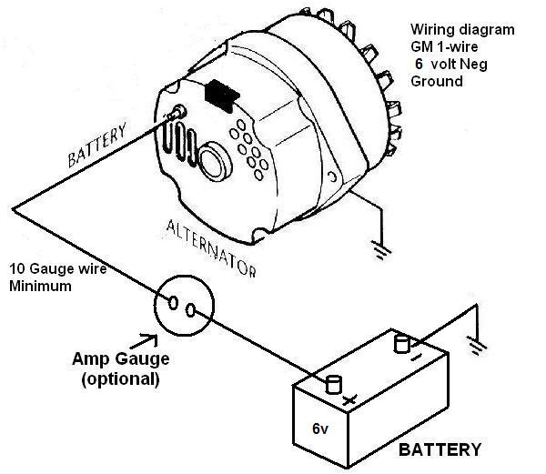
The positive terminal of the alternator is connected to the positive terminal of the battery, allowing the alternator to charge the battery when the engine is running. The negative terminal of the alternator is connected to the vehicle’s chassis ground, completing the electrical circuit and providing a return path for current to flow.
Understanding the connections between positive and negative terminals is essential for troubleshooting and repairing electrical problems. For example, a loose or corroded connection at the battery terminals can prevent the alternator from charging the battery, leading to a discharged battery and potential starting problems. Similarly, a faulty connection between the alternator and the voltage regulator can disrupt the voltage regulation process, causing overcharging or undercharging, which can damage electrical components or reduce battery life.
By studying the Wiring Diagram GM Alternator and comprehending the importance of proper connections, technicians can effectively diagnose and resolve electrical issues, ensuring the reliable operation of GM vehicles. This understanding enables them to maintain a stable electrical system, preventing potential breakdowns and ensuring the safety and performance of the vehicle.
Circuit Protection
In a Wiring Diagram GM Alternator, circuit protection devices such as fuses and circuit breakers play a crucial role in preventing electrical faults and safeguarding the electrical system. These devices are strategically placed within the wiring harness to interrupt the flow of excessive current, protecting sensitive electrical components from damage and preventing electrical fires.
Fuses are one-time-use devices that contain a thin wire designed to melt and break the circuit when the current exceeds a predetermined threshold. Circuit breakers, on the other hand, are reusable devices that can be manually reset after they trip due to excessive current. Both fuses and circuit breakers act as sacrificial elements, sacrificing themselves to protect the more expensive electrical components.
Understanding the importance of circuit protection in a Wiring Diagram GM Alternator is critical for ensuring the safe and reliable operation of the vehicle’s electrical system. For example, if the alternator malfunctions and generates excessive voltage, a fuse or circuit breaker will blow, preventing the overvoltage from reaching sensitive electronic components and potentially causing damage.
Real-life examples of circuit protection in a Wiring Diagram GM Alternator include the fuse protecting the alternator field circuit, preventing damage to the alternator in case of a short circuit. Another example is the circuit breaker protecting the battery, preventing excessive current draw that could damage the battery or cause an electrical fire.
By incorporating circuit protection into the Wiring Diagram GM Alternator, designers ensure that electrical faults are contained and minimized, reducing the risk of catastrophic damage to the electrical system and enhancing the overall safety and reliability of the vehicle.
Troubleshooting
In the context of Wiring Diagram GM Alternator, troubleshooting plays a critical role in diagnosing and resolving electrical issues that may arise within the alternator system and broader electrical network of a vehicle. Troubleshooting involves a systematic approach to identify the root cause of electrical faults, enabling technicians to repair or replace faulty components and restore proper functionality.
The Wiring Diagram GM Alternator serves as a valuable tool during the troubleshooting process, providing a detailed visual representation of the electrical connections and components within the alternator system. By studying the wiring diagram, technicians can trace electrical pathways, identify potential points of failure, and develop a logical plan for diagnosing the issue.
Real-life examples of troubleshooting within the Wiring Diagram GM Alternator include:
- Diagnosing a no-charge condition by checking for continuity in the alternator field circuit and testing the voltage regulator.
- Identifying a parasitic battery drain by isolating individual circuits using the wiring diagram and measuring current draw.
- Troubleshooting intermittent electrical issues by examining wiring harnesses for loose connections or damaged wires.
Understanding the relationship between troubleshooting and the Wiring Diagram GM Alternator is essential for technicians to effectively diagnose and repair electrical faults. By leveraging the wiring diagram as a guide, technicians can systematically approach troubleshooting, reducing diagnostic time, ensuring accurate repairs, and minimizing the risk of further electrical issues.
Testing
Within the context of “Wiring Diagram GM Alternator”, “Testing: Procedures to verify the functionality of the alternator and its components” holds significant importance, as it encompasses a series of systematic procedures used to assess the operational status, performance, and integrity of the alternator and its associated components. Through these tests, technicians can identify potential issues, pinpoint faulty parts, and ensure the proper functioning of the vehicle’s electrical system.
- Output Voltage Test: This test measures the voltage produced by the alternator at various engine speeds and loads. By comparing the measured values to the manufacturer’s specifications, technicians can determine if the alternator is generating sufficient voltage to meet the electrical demands of the vehicle.
- Ripple Voltage Test: This test evaluates the quality of the voltage produced by the alternator. Excessive ripple voltage, caused by fluctuations in the alternator’s output, can damage sensitive electronic components. By measuring the ripple voltage, technicians can assess the health of the alternator’s diodes and other internal components.
- Diode Test: Diodes play a crucial role in converting AC voltage to DC voltage in the alternator. A faulty diode can lead to reduced charging efficiency or even a no-charge condition. The diode test involves checking each diode for proper conduction and blocking characteristics, ensuring that they are functioning correctly.
- Rotor Resistance Test: The rotor is a critical component of the alternator, responsible for generating the magnetic field necessary for electricity production. The rotor resistance test measures the electrical resistance of the rotor windings. High resistance can indicate damaged windings or a faulty connection, affecting the alternator’s ability to generate electricity.
By conducting these tests and interpreting the results in conjunction with the Wiring Diagram GM Alternator, technicians can gain valuable insights into the alternator’s performance and identify potential issues. This enables them to make informed decisions regarding repairs or replacements, ensuring the reliability and efficiency of the vehicle’s electrical system.
Maintenance
Within the context of a Wiring Diagram GM Alternator, maintenance plays a critical role in preserving the alternator’s functionality, ensuring optimal performance, and extending its service life. Regular checks and timely replacements of components are essential to prevent premature failure, enhance reliability, and maintain the electrical system’s efficiency.
One of the key aspects of maintenance involves inspecting and testing the alternator’s components, including the brushes, slip rings, and bearings. Worn brushes or damaged slip rings can compromise the alternator’s ability to generate electricity, leading to a reduced charging capacity or even a complete failure. Regular inspections and timely replacements of these components can prevent such issues, ensuring the alternator’s consistent performance.Another important aspect of maintenance is monitoring the alternator’s output voltage and current. Deviations from the specified values can indicate underlying problems, such as a faulty voltage regulator or failing diodes. By regularly checking the alternator’s output, technicians can identify potential issues early on, enabling timely repairs and preventing more severe damage to the electrical system.Furthermore, maintaining proper belt tension is crucial for the alternator’s operation. A loose belt can cause slippage, reducing the alternator’s ability to generate electricity and potentially leading to overheating. Regular belt inspections and adjustments ensure optimal belt tension, preventing these issues and maintaining the alternator’s efficiency.By adhering to a regular maintenance schedule and following the guidelines outlined in the Wiring Diagram GM Alternator, technicians can proactively address potential issues, minimize the risk of alternator failure, and ensure the vehicle’s electrical system operates at its optimal level.
Safety Precautions
In the context of Wiring Diagram Gm Alternator, Safety Precautions hold utmost importance, providing indispensable guidelines for handling electrical components safely. These precautions prioritize the well-being of individuals, prevent electrical hazards, and ensure the integrity of the alternator system. Understanding and adhering to these safety measures are paramount for technicians and professionals working with automotive electrical systems.
- Risk Assessment and Personal Protection: Before commencing any electrical work, a thorough risk assessment must be conducted to identify potential hazards. Technicians should wear appropriate personal protective equipment (PPE), including insulated gloves, safety glasses, and non-conductive footwear, to minimize the risk of electrical shock, burns, or arc flash.
- De-energizing the System: Prior to performing any hands-on work, it is crucial to de-energize the electrical system by disconnecting the battery. This eliminates the presence of live voltage, preventing inadvertent electrical contact and ensuring a safe working environment.
- Proper Tool Usage: Utilizing the correct tools and equipment is essential. Insulated tools with non-conductive handles prevent electrical shock hazards. Proper grounding techniques should also be employed to dissipate any stray electrical charges.
- Environmental Considerations: Electrical work should be performed in a clean, dry, and well-ventilated area. Moisture, dust, or flammable materials can pose safety risks, increasing the likelihood of electrical faults or fires.
Adhering to these safety precautions is non-negotiable when working with Wiring Diagram Gm Alternator. By implementing these measures, technicians can safeguard themselves, prevent accidents, and ensure the proper functioning of the electrical system. Neglecting safety protocols can lead to severe consequences, including electrical shock, component damage, or even fire, emphasizing the paramount importance of safety in this domain.
System Integration
Within the comprehensive framework of the “Wiring Diagram GM Alternator,” the aspect of “System Integration: Interactions between the alternator and other electrical systems” assumes great significance. This facet delves into the intricate interplay between the alternator and various components of the vehicle’s electrical architecture, highlighting their interconnectedness and collaborative functionality.
- Battery Management: The alternator closely coordinates with the battery to maintain optimal battery charge levels. It monitors the battery’s voltage and adjusts its output accordingly, ensuring a steady supply of electrical power to meet the demands of the electrical system and prevent battery overcharging or undercharging.
- Electrical Load Management: The alternator dynamically adjusts its output based on the electrical load demand of the vehicle. When electrical accessories such as headlights, air conditioning, or audio systems are activated, the alternator increases its output to meet the increased demand while maintaining a stable voltage level.
- Voltage Regulation: The alternator works in conjunction with the voltage regulator to ensure that the electrical system operates within a specific voltage range. The voltage regulator monitors the system voltage and sends feedback signals to the alternator, which adjusts its excitation current to maintain the desired voltage level.
- Fault Detection and Response: The alternator can communicate with other electrical modules in the vehicle, such as the powertrain control module, to provide information about its operating status and potential faults. This enables the vehicle’s systems to respond appropriately, such as adjusting engine performance or activating warning lights, to mitigate potential issues.
Understanding “System Integration: Interactions between the alternator and other electrical systems” is crucial for comprehending the holistic functioning of the “Wiring Diagram GM Alternator.” These interactions underscore the importance of proper system design, component compatibility, and effective communication between electrical components to ensure the reliable operation and performance of the vehicle’s electrical system.
Computerized Control
Within the context of “Wiring Diagram GM Alternator,” “Computerized Control: Integration with engine control modules for efficient power management” plays a pivotal role in optimizing the alternator’s performance and enhancing the overall efficiency of the vehicle’s electrical system.
Engine control modules (ECMs) are the brains of modern vehicles, responsible for managing various aspects of engine operation, including fuel injection, ignition timing, and emissions control. The integration of ECMs with the alternator allows for real-time monitoring and control of the alternator’s output, ensuring that the electrical system operates in harmony with the engine’s needs.
A key benefit of computerized control is its ability to adjust the alternator’s output based on the vehicle’s electrical load and engine operating conditions. For instance, when the vehicle is idling or operating at low speeds, the alternator can reduce its output to minimize parasitic losses and improve fuel efficiency. Conversely, when the electrical load increases, such as when multiple accessories are activated or during acceleration, the alternator can ramp up its output to meet the demand.
Moreover, computerized control enables the alternator to respond to changes in battery voltage and state of charge. By monitoring the battery’s voltage, the ECM can adjust the alternator’s output to maintain an optimal charging voltage, preventing overcharging or undercharging.
In summary, the integration of computerized control with the alternator through the Wiring Diagram GM Alternator leads to enhanced power management, improved fuel efficiency, and a more stable electrical system. This integration is a critical component of modern vehicle electrical systems, contributing to overall vehicle performance and efficiency.


![[DIAGRAM] Wiring Diagram For 1 Wire Gm Alternator](https://i0.wp.com/capestarter.com/ESW/Files/2wire12volt.jpg?w=665&ssl=1)


Related Posts


