A wiring diagram for trailer tail lights is a detailed plan that illustrates the electrical connections between the trailer’s tail lights and the towing vehicle. It guides the proper installation and configuration of wiring to ensure the tail lights function correctly, providing visibility and safety on the road.
Wiring diagrams for trailer tail lights are crucial for ensuring the trailer’s tail lights are adequately connected and functional, meeting regulatory standards and preventing potential electrical hazards. They provide a systematic approach for troubleshooting any issues with the tail lights, saving time and effort. Historically, the standardization of wiring configurations has simplified the installation process, reducing the risk of errors.
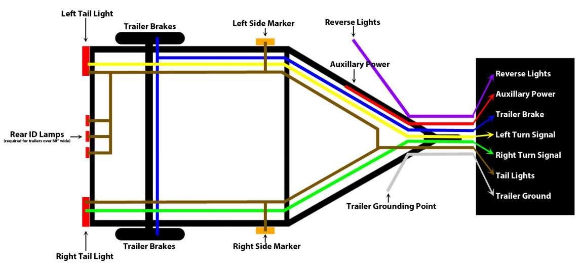
This article will delve into the intricacies of wiring diagrams for trailer tail lights, exploring the different types of connections, color-coding schemes, ground systems, and problem-solving techniques. It aims to provide a comprehensive understanding of these diagrams, equipping readers with the knowledge to ensure the proper functioning and safety of their trailer’s lighting systems.
Wiring diagrams for trailer tail lights are indispensable for ensuring the safe and compliant operation of trailers on the road. They provide a visual representation of the electrical connections between the trailer’s tail lights and the towing vehicle, guiding proper installation and troubleshooting.
- Components: Wiring diagrams detail the various electrical components involved, including tail lights, connectors, wires, and grounding points.
- Color-coding: Standard color-coding schemes are used to identify different types of wires, simplifying the installation process.
- Grounding: Proper grounding is crucial for the correct functioning of the tail lights, and wiring diagrams specify the appropriate grounding points.
- Circuit protection: Fuses or circuit breakers protect the electrical system from overloads, and wiring diagrams indicate their location and specifications.
- Testing: Wiring diagrams assist in testing the tail lights to ensure they are functioning correctly before hitting the road.
- Troubleshooting: In case of any issues with the tail lights, wiring diagrams aid in identifying potential problems and their solutions.
- Regulations: Wiring diagrams help ensure compliance with regulatory standards, such as those set by the Department of Transportation (DOT).
- Compatibility: Wiring diagrams are tailored to specific trailer and towing vehicle combinations, ensuring compatibility and proper functioning.
Understanding these key aspects is essential for anyone working with trailer tail lights, whether for installation, maintenance, or troubleshooting. Wiring diagrams empower individuals to confidently handle electrical connections, ensuring the safety and reliability of their trailer lighting systems.
Components
In the context of wiring diagrams for trailer tail lights, the components listed are critical elements that must be precisely connected to ensure the tail lights function correctly and meet safety standards. These components work in conjunction to create a complete electrical circuit that allows the tail lights to illuminate when activated.
The absence or malfunction of any of these components can result in non-functioning tail lights, compromising the safety of the trailer and other road users. Wiring diagrams provide a clear understanding of how these components interact, enabling proper installation, maintenance, and troubleshooting.
Real-life examples of these components within a wiring diagram for trailer tail lights include:
- Tail lights: The primary lighting units at the rear of the trailer, providing visibility and signaling.
- Connectors: Electrical connectors allow for the connection and disconnection of the trailer’s wiring system to the towing vehicle.
- Wires: Conductors that carry electrical current from the towing vehicle to the tail lights.
- Grounding points: Essential for completing the electrical circuit and preventing electrical hazards.
Understanding the relationship between these components and their proper configuration is crucial for ensuring the reliability and safety of trailer tail light systems. Wiring diagrams empower individuals to confidently work with these electrical components, ensuring their trailers are roadworthy and compliant with regulations.
Color-coding
Within the context of “Wiring Diagram For Trailer Tail Lights”, color-coding plays a critical role in simplifying the installation process by assigning distinct colors to different types of wires. This standardization ensures consistency and clarity, allowing individuals to quickly identify the purpose and function of each wire.
- Function Identification: Color-coding helps differentiate between wires carrying different functions, such as ground wires, power wires, and signal wires, making it easier to connect them correctly.
- Simplified Troubleshooting: When troubleshooting electrical issues, color-coding enables quick identification of faulty or disconnected wires, reducing repair time and effort.
- Compatibility: Standard color-coding schemes promote compatibility between different trailer and towing vehicle combinations, ensuring proper connections and functionality.
- Industry Standards: Adhering to color-coding standards ensures compliance with industry regulations and best practices, enhancing safety and reliability.
In summary, color-coding in wiring diagrams for trailer tail lights serves as a universal language, simplifying installation, troubleshooting, and compliance. By following these standardized color-coding schemes, individuals can confidently work with trailer electrical systems, ensuring proper functioning and roadworthiness.
Grounding
In the context of “Wiring Diagram For Trailer Tail Lights,” grounding plays a critical role in ensuring the correct functioning of the tail lights. Grounding provides a path for electrical current to complete the circuit, allowing the tail lights to illuminate when activated. Wiring diagrams specify the appropriate grounding points, which are typically located on the chassis or frame of the trailer.
Without proper grounding, the electrical circuit will not be complete, and the tail lights will not function. This can pose a safety hazard, as other vehicles may not be able to see the trailer’s tail lights, increasing the risk of an accident.
Real-life examples of grounding within “Wiring Diagram For Trailer Tail Lights” include:
- Connecting the negative terminal of the tail light assembly to the trailer’s chassis.
- Using a separate ground wire to connect the trailer’s frame to the towing vehicle’s chassis.
Understanding the importance of proper grounding and following the specifications provided in wiring diagrams is crucial for ensuring the reliability and safety of trailer tail light systems. By providing a clear representation of the grounding points, wiring diagrams empower individuals to confidently work with trailer electrical systems, ensuring proper functioning and compliance with regulations.
Circuit protection
Within the context of “Wiring Diagram For Trailer Tail Lights,” circuit protection plays a critical role in ensuring the safety and reliability of the electrical system. Wiring diagrams indicate the location and specifications of fuses or circuit breakers, which are crucial components for protecting the electrical system from overloads.
Overloads can occur when too much electrical current flows through the system, potentially causing wires to overheat and leading to electrical fires or damage to the tail lights. Fuses and circuit breakers act as safety switches, interrupting the electrical circuit when the current exceeds a predetermined limit, preventing damage to the electrical system and the trailer.
Real-life examples of circuit protection within “Wiring Diagram For Trailer Tail Lights” include:
- Installing a fuse or circuit breaker in the power line to the tail lights.
- Using fuses or circuit breakers with the appropriate amperage rating for the tail light system.
Understanding the importance of circuit protection and following the specifications provided in wiring diagrams is crucial for ensuring the safety and reliability of trailer tail light systems. By providing a clear representation of the location and specifications of fuses or circuit breakers, wiring diagrams empower individuals to confidently work with trailer electrical systems, ensuring proper functioning and compliance with regulations.
Testing
Within the context of “Wiring Diagram For Trailer Tail Lights,” testing is a crucial aspect that ensures the safety and reliability of the trailer’s lighting system. Wiring diagrams play a vital role in guiding the testing process, providing a visual representation of the electrical connections and aiding in the identification of any potential issues.
- Electrical Continuity: Wiring diagrams assist in testing the continuity of the electrical circuit, ensuring that current can flow from the power source to the tail lights without any breaks or interruptions.
- Tail Light Functionality: Wiring diagrams provide a systematic approach to testing the functionality of each tail light, verifying that they illuminate properly when activated.
- Grounding Verification: Proper grounding is essential for the correct functioning of tail lights. Wiring diagrams guide the testing of grounding points to ensure a complete electrical circuit.
- Compliance with Regulations: Testing tail lights using wiring diagrams helps ensure compliance with regulatory standards, such as those set by the Department of Transportation (DOT), promoting safety on the road.
By facilitating thorough testing of trailer tail lights, wiring diagrams empower individuals to confidently verify the proper functioning and roadworthiness of their trailers. This proactive approach minimizes the risk of electrical failures, enhances visibility, and contributes to overall road safety.
Troubleshooting
When dealing with “Wiring Diagram For Trailer Tail Lights,” troubleshooting plays a crucial role in ensuring the trailer’s lighting system operates correctly and safely. Wiring diagrams serve as invaluable tools in this process, providing a detailed visual representation of the electrical connections and aiding in the identification of potential problems and their solutions.
As a critical component of “Wiring Diagram For Trailer Tail Lights,” troubleshooting empowers individuals to diagnose and resolve electrical issues with the tail lights. The wiring diagram serves as a roadmap, guiding the user through the electrical system, enabling them to pinpoint the source of problems and determine appropriate solutions.
Real-life examples of troubleshooting within “Wiring Diagram For Trailer Tail Lights” include:
- Identifying a blown fuse or tripped circuit breaker as the cause of non-functioning tail lights.
- Tracing a faulty wire causing intermittent tail light operation.
- Diagnosing a grounding issue leading to dim or flickering tail lights.
The practical applications of understanding troubleshooting techniques in “Wiring Diagram For Trailer Tail Lights” are numerous:
- Ensuring the trailer’s tail lights are always in good working order, enhancing visibility and safety on the road.
- Reducing downtime and maintenance costs by resolving electrical issues promptly and effectively.
- Promoting self-sufficiency in trailer maintenance, allowing individuals to address minor electrical problems without relying solely on professional assistance.
In summary, troubleshooting is an integral aspect of “Wiring Diagram For Trailer Tail Lights,” providing individuals with the knowledge and tools to maintain the trailer’s lighting system effectively. By understanding troubleshooting techniques and leveraging wiring diagrams, individuals can ensure the safety and reliability of their trailers, contributing to their overall roadworthiness.
Regulations
Within the context of “Wiring Diagram For Trailer Tail Lights,” regulations play a crucial role in ensuring the safety and legality of trailer lighting systems. Wiring diagrams serve as essential tools in achieving compliance with regulatory standards, particularly those established by the Department of Transportation (DOT).
DOT regulations mandate specific requirements for trailer tail lights, including:
- Number and placement of tail lights
- Color and intensity of tail lights
- Electrical connections and wiring specifications
Wiring diagrams provide a clear visual representation of how to connect the tail lights to the towing vehicle’s electrical system in accordance with these regulations. By adhering to the specifications outlined in the wiring diagram, individuals can ensure that their trailer’s tail lights meet DOT standards and operate safely and effectively.
Real-life examples of regulations within “Wiring Diagram For Trailer Tail Lights” include:
- Using a wiring diagram to determine the correct wire gauge for the tail lights, as specified by DOT regulations.
- Ensuring that the tail lights are wired to the correct terminals on the towing vehicle’s electrical connector, as per DOT requirements.
Understanding the importance of regulations and following the specifications provided in wiring diagrams is crucial for ensuring the safety and legality of trailer tail light systems. By promoting compliance with DOT standards, wiring diagrams contribute to the overall safety and reliability of trailers on the road.
Compatibility
Within the context of “Wiring Diagram For Trailer Tail Lights,” compatibility stands as a fundamental aspect that ensures the safe and effective operation of trailer lighting systems. Wiring diagrams play a pivotal role in achieving compatibility between the trailer and the towing vehicle, addressing the unique electrical requirements of different combinations.
The significance of compatibility within “Wiring Diagram For Trailer Tail Lights” stems from the varying electrical configurations of trailers and towing vehicles. Each combination demands a tailored approach to ensure that the tail lights function correctly and meet regulatory standards. Wiring diagrams provide this critical information, specifying the appropriate connections and components for each specific combination.
Real-life examples of compatibility within “Wiring Diagram For Trailer Tail Lights” include:
- Matching the wire gauge of the trailer’s tail lights to the towing vehicle’s electrical system.
- Ensuring that the tail lights are compatible with the voltage and amperage of the towing vehicle.
- Selecting the correct connectors and adapters to establish a secure and functional connection between the trailer and the towing vehicle.
Understanding the importance of compatibility and following the specifications provided in wiring diagrams is crucial for ensuring the safe and reliable operation of trailer tail light systems. By promoting compatibility between the trailer and the towing vehicle, wiring diagrams contribute to the overall safety and reliability of trailers on the road.
In summary, compatibility is a critical component of “Wiring Diagram For Trailer Tail Lights,” providing the necessary guidance to ensure that trailer tail lights function correctly and meet regulatory standards. By understanding the relationship between compatibility and wiring diagrams, individuals can make informed decisions when selecting and installing trailer tail lights, contributing to the safety and reliability of their trailers.


Related Posts


