Definition and example: Wiring Diagram For Refrigerator Compressor
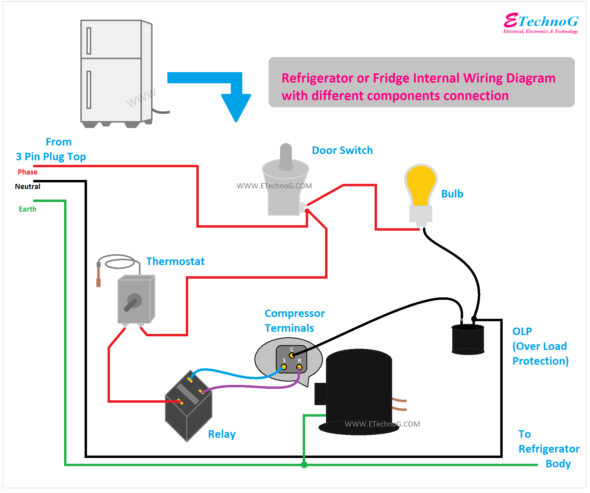
A wiring diagram for a refrigerator compressor is a technical document that illustrates the electrical connections between the various components of the compressor, including the motor, capacitor, and overload protector. It provides a visual representation of the electrical circuit and serves as a guide for troubleshooting and repair.
Importance, benefits, and historical context:
Wiring diagrams are essential for understanding the functionality and troubleshooting electrical systems, especially those found in complex appliances like refrigerators. They offer several benefits, including improved safety, reduced downtime, and simplified maintenance procedures. Historically, wiring diagrams have been created manually using drafting tools, but modern software applications allow for digital creation and sharing.
Transition to main article topics:
This article will delve deeper into the significance of wiring diagrams for refrigerator compressors, exploring their role in ensuring proper operation, troubleshooting common issues, and ensuring the safe and efficient functioning of refrigeration systems.
Introduction highlighting the importance of the key aspects:
Wiring diagrams for refrigerator compressors play a critical role in the proper functioning, troubleshooting, and maintenance of refrigeration systems. Understanding their various essential aspects is crucial for ensuring the safe and efficient operation of refrigerators.
- Key aspect: Schematic representation:
Wiring diagrams provide a visual schematic of the electrical connections within the compressor, aiding in comprehension and troubleshooting.
Key aspect: Troubleshooting guide:
Diagrams assist technicians in identifying potential issues by providing a clear overview of the electrical circuit.
Key aspect: Maintenance roadmap:
They serve as a roadmap for maintenance procedures, guiding technicians through the necessary steps.
Key aspect: Safety assurance:
Diagrams promote safety by ensuring proper connections and preventing electrical hazards.
Key aspect: Component identification:
They help identify and locate specific components within the compressor, facilitating repairs.
Key aspect: Standardization:
Wiring diagrams follow standardized conventions, enabling universal understanding and interchangeability of components.
Key aspect: Training tool:
Diagrams are valuable training tools for technicians, providing a visual aid for understanding compressor operation.
Key aspect: Documentation:
They serve as technical documentation, recording the electrical configuration of the compressor for future reference.
Key aspect: Optimization:
Diagrams enable optimization of the electrical system, ensuring peak performance and energy efficiency.
Detailed discussion on the key aspects, through examples, connections, or linkage to the main topic:
For instance, the schematic representation aspect allows technicians to quickly visualize the flow of electricity through the compressor, making it easier to identify potential issues such as short circuits or loose connections. Similarly, the troubleshooting guide aspect provides a systematic approach to diagnosing problems, reducing downtime and repair costs.
Key aspect
In the context of wiring diagrams for refrigerator compressors, schematic representation holds significant importance. It provides a visual representation of the electrical connections within the compressor, offering several advantages for technicians and users alike.
-
Visual comprehension
Schematic diagrams simplify complex electrical circuits, allowing technicians to quickly visualize the flow of electricity and identify potential issues. -
Troubleshooting guide
Diagrams serve as a troubleshooting guide, helping technicians systematically diagnose problems by tracing the electrical connections and identifying potential faults. -
Maintenance roadmap
Schematic representations provide a roadmap for maintenance procedures, guiding technicians through the necessary steps to ensure proper functioning and longevity of the compressor. -
Component identification
Diagrams help identify and locate specific components within the compressor, facilitating repairs and replacements when necessary.
Overall, schematic representation is a crucial aspect of wiring diagrams for refrigerator compressors, enabling technicians to effectively troubleshoot, maintain, and repair these essential components of refrigeration systems.
Key aspect: Troubleshooting guide
Wiring diagrams for refrigerator compressors serve as invaluable troubleshooting guides for technicians, empowering them to diagnose and resolve issues efficiently. These diagrams provide a visual representation of the electrical connections within the compressor, enabling technicians to systematically trace the flow of electricity and identify potential faults.
-
Identifying potential parts
Troubleshooting guides assist technicians in identifying the specific parts or components within the compressor that may be causing the issue. This helps narrow down the search and facilitates targeted repairs. -
Real-life examples
Wiring diagrams provide real-life examples of common troubleshooting scenarios, such as identifying a blown fuse or a loose connection. This practical guidance helps technicians quickly resolve issues and restore the compressor to proper functioning. -
Implications for compressor performance
Troubleshooting guides empower technicians to understand the implications of electrical faults on the overall performance of the compressor. This knowledge enables them to prioritize repairs and ensure the longevity of the refrigeration system. -
Safety considerations
Troubleshooting guides also incorporate safety considerations,
In conclusion, troubleshooting guides are a critical component of wiring diagrams, enabling technicians to effectively diagnose and resolve issues with refrigerator compressors. By providing a visual representation of the electrical connections and offering real-life examples, these guides empower technicians to ensure the efficient and safe operation of refrigeration systems.
Key aspect: Maintenance roadmap:
Wiring diagrams for refrigerator compressors serve as comprehensive maintenance roadmaps, guiding technicians through the necessary steps to ensure proper functioning and longevity of these essential components of refrigeration systems. These diagrams provide a visual representation of the electrical connections within the compressor, enabling technicians to systematically identify potential issues and perform targeted maintenance procedures.
-
Identifying potential parts
Maintenance roadmaps assist technicians in identifying the specific parts or components within the compressor that may require maintenance or replacement. This helps plan and prepare for necessary repairs, minimizing downtime and ensuring efficient operation. -
Real-life examples
Wiring diagrams provide real-life examples of common maintenance scenarios, such as cleaning of the condenser coils or replacing worn-out gaskets. These practical examples help technicians visualize and understand the maintenance procedures, leading to effective upkeep of the compressor. -
Implications for compressor performance
Maintenance roadmaps empower technicians to understand the implications of proper maintenance on the overall performance of the compressor. Regular maintenance helps prevent premature failures, reduces energy consumption, and ensures the longevity of the refrigeration system.
In conclusion, maintenance roadmaps are an essential component of wiring diagrams for refrigerator compressors, enabling technicians to effectively maintain and service these critical components. By providing a visual representation of the electrical connections and offering real-life examples, these roadmaps empower technicians to ensure the efficient and safe operation of refrigeration systems.
Key aspect: Safety assurance:
Wiring diagrams for refrigerator compressors play a vital role in ensuring the safety of technicians and users alike. They provide a visual representation of the electrical connections within the compressor, enabling technicians to identify potential hazards and implement appropriate safety measures.
Safety assurance is a critical component of wiring diagrams for refrigerator compressors, as it helps prevent electrical accidents, fires, and other dangerous situations. By following the instructions and guidelines provided in the diagram, technicians can ensure that the compressor is installed, maintained, and repaired safely.
Real-life examples of safety assurance in wiring diagrams for refrigerator compressors include:
- Identification of potential shock hazards
- Instructions for proper grounding
- Guidelines for safe handling of electrical components
Understanding the connection between safety assurance and wiring diagrams for refrigerator compressors is essential for ensuring the safe and efficient operation of refrigeration systems. By adhering to the safety guidelines provided in these diagrams, technicians can minimize risks and protect themselves and others from harm.
Key aspect: Component identification:
Wiring diagrams for refrigerator compressors serve as essential tools for identifying and locating specific components within the compressor. This is critical for troubleshooting, maintenance, and repair procedures, as it enables technicians to quickly and accurately pinpoint the source of any issues.
Component identification is a crucial component of wiring diagrams for refrigerator compressors, as it provides a visual representation of the electrical connections and the physical layout of the various components. This information is essential for understanding the functionality of the compressor and for performing any necessary repairs or replacements.
Real-life examples of component identification within wiring diagrams for refrigerator compressors include:
- Identifying the location of the compressor motor
- Determining the type of capacitor used in the compressor
- Locating the overload protector
Understanding the connection between component identification and wiring diagrams for refrigerator compressors is essential for effective troubleshooting and repair. By being able to identify and locate specific components, technicians can quickly diagnose problems and implement appropriate solutions to ensure the efficient and safe operation of refrigeration systems.
Key aspect: Standardization:
Standardization is a critical aspect of wiring diagrams for refrigerator compressors, ensuring consistency, interchangeability, and simplified maintenance procedures. It involves the use of established conventions and symbols to represent electrical components and connections, providing a common language for technicians and manufacturers.
-
Universal understanding
Standardized wiring diagrams promote universal understanding and interchangeability of components, regardless of the manufacturer or model of the refrigerator compressor. This simplifies troubleshooting and repair procedures, as technicians can easily interpret and navigate the diagrams. -
Efficient troubleshooting
Standardization enables efficient troubleshooting by providing a consistent framework for identifying and locating potential issues. Technicians can quickly identify common faults and apply standardized troubleshooting techniques, reducing downtime and repair costs. -
Simplified maintenance
Standardized wiring diagrams simplify maintenance procedures by providing clear instructions and guidelines. Technicians can easily follow the diagrams to perform routine maintenance tasks, such as cleaning, lubrication, and component replacement. -
Enhanced safety
Standardization contributes to enhanced safety by ensuring proper and consistent electrical connections. Adherence to standardized practices minimizes the risk of electrical hazards, such as short circuits and overheating, promoting a safe working environment for technicians.
In summary, standardization is a key aspect of wiring diagrams for refrigerator compressors, fostering universal understanding, efficient troubleshooting, simplified maintenance, and enhanced safety. By adhering to established conventions and symbols, these diagrams provide a common language for technicians, enabling effective communication and collaboration in the maintenance and repair of refrigeration systems.
Key aspect: Training tool:
Wiring diagrams for refrigerator compressors serve as valuable training tools for technicians, providing a visual and interactive resource to enhance their understanding and troubleshooting skills. They offer several benefits in this regard:
-
Visual representation
Wiring diagrams provide a visual representation of the electrical connections within the compressor, making it easier for trainees to understand the flow of electricity and identify potential issues. -
Interactive learning
Diagrams can be used for interactive learning, allowing trainees to trace the electrical connections and simulate troubleshooting scenarios. -
Real-life examples
Wiring diagrams often include real-life examples of common troubleshooting scenarios, helping trainees apply their knowledge to practical situations.
The understanding gained from wiring diagrams empowers technicians to perform their jobs more effectively and efficiently. By providing a solid foundation in electrical concepts and troubleshooting techniques, wiring diagrams contribute to the development of competent and skilled refrigeration technicians.
Key aspect: Documentation:
Documentation plays a crucial role in the context of wiring diagrams for refrigerator compressors, ensuring the accurate recording and preservation of electrical configurations for future reference and maintenance purposes. It provides a comprehensive record of the compressor’s electrical system, including the connections, components, and specifications.
-
Circuit schematics
Wiring diagrams serve as circuit schematics, documenting the electrical connections between various components within the compressor, such as the motor, capacitor, and overload protector. These schematics provide a visual representation of the circuit’s layout and functionality.
-
Component identification
Documentation includes detailed identification of each component used in the compressor, along with its specifications and location within the circuit. This information is essential for troubleshooting, maintenance, and repair procedures.
-
Maintenance history
Wiring diagrams can serve as a maintenance history log, recording repairs, replacements, and modifications performed on the compressor over its lifespan. This information aids in tracking maintenance activities and ensuring the continued safe and efficient operation of the compressor.
-
Compliance and safety
Proper documentation of wiring diagrams is essential for compliance with electrical codes and safety regulations. It ensures that the compressor’s electrical system meets industry standards and minimizes the risk of electrical hazards.
In summary, documentation is a vital aspect of wiring diagrams for refrigerator compressors, providing a permanent record of the electrical configuration, component specifications, and maintenance history. This documentation is crucial for troubleshooting, maintenance, safety compliance, and ensuring the reliable and efficient operation of refrigeration systems.
Key aspect: Optimization:
In the context of wiring diagrams for refrigerator compressors, optimization plays a pivotal role in ensuring peak performance, energy efficiency, and extended lifespan of the compressor. Wiring diagrams provide a visual representation of the electrical connections, enabling technicians to analyze and optimize the electrical system for maximum efficiency and reliability.
-
Component selection
Wiring diagrams assist in selecting optimal components for the compressor, such as the motor, capacitor, and overload protector. By considering factors like power consumption, operating temperature, and load requirements, technicians can choose components that match the specific needs of the refrigeration system, resulting in improved efficiency and reliability.
-
Circuit layout
Optimization of the circuit layout involves arranging the components within the compressor in a manner that minimizes electrical losses and maximizes energy efficiency. Wiring diagrams allow technicians to visualize the circuit layout and identify potential areas for improvement, such as reducing wire lengths or optimizing component placement for better heat dissipation.
-
Electrical parameters
Wiring diagrams enable technicians to fine-tune electrical parameters, such as voltage, current, and power factor, to achieve optimal operating conditions for the compressor. By adjusting these parameters within acceptable ranges, technicians can improve compressor performance, reduce energy consumption, and extend the lifespan of the system.
In summary, optimization is a crucial aspect of wiring diagrams for refrigerator compressors, empowering technicians to make informed decisions regarding component selection, circuit layout, and electrical parameters. By optimizing the electrical system, technicians can ensure peak performance, enhanced energy efficiency, and extended lifespan of the compressor, leading to improved refrigeration system operation and reduced operating costs.


Related Posts


