A wiring diagram for Nest is a plan that shows how to connect the Nest thermostat to an HVAC system. It provides detailed instructions and diagrams illustrating the wiring connections between the thermostat and the heating and cooling equipment.
Wiring diagrams for Nest are essential for ensuring the proper installation and functionality of the thermostat. They guide electricians and homeowners through the wiring process, ensuring that the thermostat is connected correctly to control the HVAC system effectively. Additionally, wiring diagrams have a long history in the electrical industry, providing a standardized method for documenting and communicating wiring configurations.
This article will delve into the specifics of wiring diagrams for Nest thermostats, including the different types of wiring configurations, common troubleshooting issues, and best practices for ensuring a successful installation.
Understanding the essential aspects of wiring diagrams for Nest thermostats is crucial for successful installation and operation. These diagrams provide detailed instructions and plans for connecting the thermostat to HVAC systems, ensuring proper functionality and control over heating and cooling equipment.
- Types: Common, single-stage, multi-stage, heat pump
- Components: Thermostat, wires, terminals, circuit breaker
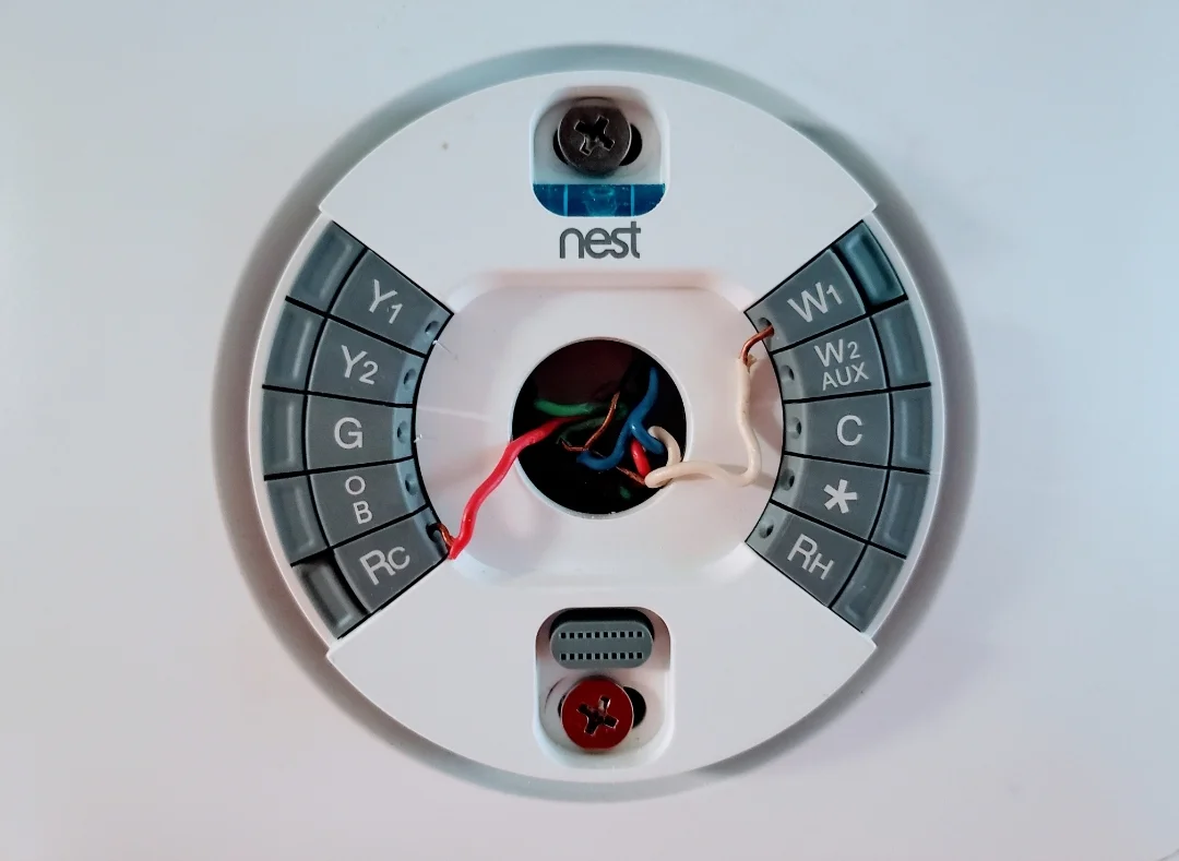
- Connections: R, C, G, Y, W, O/B
- Troubleshooting: Power issues, wiring errors, compatibility
- Safety: Electrical hazards, professional installation
- Tools: Screwdriver, wire strippers, multimeter
- Codes: Building codes, electrical standards
- History: Evolution of wiring diagrams in electrical industry
- Alternatives: Wireless thermostats, smart thermostats
- Future: Advancements in thermostat technology and connectivity
These aspects encompass the key elements of wiring diagrams for Nest thermostats, providing a comprehensive understanding of their importance, components, installation, troubleshooting, and broader implications. By considering these factors, homeowners and electricians can ensure the safe and efficient operation of their Nest thermostats, optimizing home comfort and energy consumption.
Types
Understanding the different types of wiring diagrams for Nest thermostats is essential for proper installation and functionality. These diagrams vary depending on the type of HVAC system being used, including common, single-stage, multi-stage, and heat pump systems. Each type requires specific wiring configurations to ensure compatibility and optimal performance.
- Common: Basic wiring diagram for simple HVAC systems with a single heating and cooling stage. It typically involves connecting the thermostat to the R, C, G, and Y terminals.
- Single-stage: Similar to common wiring, but designed for systems with a single-stage compressor or heating element. It typically involves additional connections to the O/B terminal for reversing valves in heat pump systems.
- Multi-stage: More complex wiring diagram for systems with multiple stages of heating or cooling. It involves connecting the thermostat to additional terminals, such as W2 or Y2, to control the different stages of operation.
- Heat pump: Specialized wiring diagram designed for heat pump systems that can both heat and cool. It typically involves additional connections to the O/B terminal for reversing valves and may require a separate thermostat model.
Choosing the correct wiring diagram for the specific HVAC system is crucial for ensuring proper functionality and energy efficiency. Mismatched wiring can lead to operational issues, reduced comfort, and potential damage to the thermostat or HVAC equipment. Therefore, it is recommended to consult the manufacturer’s instructions or an experienced electrician for guidance on selecting and installing the appropriate wiring diagram for a Nest thermostat.
Components
In the realm of “Wiring Diagram For Nest”, understanding the components involved is essential for successful installation and operation. This includes the thermostat itself, as well as the wires, terminals, and circuit breaker that facilitate the connection and power supply to the HVAC system. Each component plays a vital role in ensuring proper functionality and safety.
- Thermostat: The brain of the HVAC system, responsible for sensing temperature and controlling the heating and cooling equipment.
- Wires: Conductors that carry electrical signals and power between the thermostat and the HVAC equipment.
- Terminals: Electrical connection points on the thermostat and HVAC equipment where wires are attached.
- Circuit breaker: A safety device that protects the electrical circuit from overcurrent, preventing damage to the thermostat and HVAC equipment.
These components work together to provide a safe and effective connection between the thermostat and the HVAC system. Proper installation and understanding of these components are crucial for ensuring optimal performance, energy efficiency, and longevity of the system.
Connections
In the realm of “Wiring Diagram For Nest”, the connections denoted by R, C, G, Y, W, and O/B play a critical role in establishing a functional link between the thermostat and the HVAC system. These letters represent specific terminals on both the thermostat and the HVAC equipment, and each connection serves a distinct purpose in controlling the heating and cooling functions.
The R terminal, often referred to as the “power” terminal, provides 24 volts of power to the thermostat. The C terminal, or “common” terminal, completes the circuit and provides a return path for the electrical current. The G terminal, or “fan” terminal, controls the operation of the fan, which circulates air throughout the heating and cooling system. The Y terminal, or “cooling” terminal, activates the cooling system, while the W terminal, or “heating” terminal, activates the heating system. Finally, the O/B terminal, or “reversing valve” terminal, is used in heat pump systems to switch between heating and cooling modes.
Understanding the purpose and proper connection of these terminals is essential for the successful installation and operation of a Nest thermostat. Incorrect wiring can lead to malfunctions, reduced efficiency, or even damage to the thermostat or HVAC equipment. Therefore, it is crucial to follow the manufacturer’s instructions carefully and consult with a qualified electrician if any uncertainties arise during the wiring process.
Troubleshooting
In the context of “Wiring Diagram For Nest”, troubleshooting plays a crucial role in ensuring the proper functionality and optimal performance of the thermostat and the HVAC system it controls. Various issues can arise during installation or operation, and understanding how to troubleshoot these problems is essential for maintaining a comfortable and energy-efficient indoor environment.
- Power Issues: Verify that the thermostat is receiving power from the circuit breaker and that the wiring connections are secure. Check if the batteries in the thermostat are fresh and properly installed.
- Wiring Errors: Incorrect wiring can lead to malfunctions or damage to the thermostat or HVAC equipment. Ensure that all wires are connected to the correct terminals on both the thermostat and the HVAC unit, following the manufacturer’s instructions precisely.
- Compatibility: Not all thermostats are compatible with all HVAC systems. Check the manufacturer’s specifications to confirm compatibility between the Nest thermostat and the specific HVAC system being used. Mismatched components can result in operational issues or reduced efficiency.
- Thermostat Malfunctions: In some cases, the thermostat itself may malfunction due to hardware or software issues. Resetting the thermostat or updating its firmware may resolve the problem. If the issue persists, professional repair or replacement of the thermostat may be necessary.
By understanding and addressing these common troubleshooting aspects related to power issues, wiring errors, and compatibility, homeowners and technicians can ensure the reliable and efficient operation of their Nest thermostat and HVAC system. Regular maintenance and prompt troubleshooting can extend the lifespan of these components, optimize energy consumption, and maintain a comfortable indoor climate.
Safety
In the context of “Wiring Diagram For Nest”, understanding and adhering to safety guidelines is paramount to prevent electrical hazards and ensure the proper functioning of the thermostat and HVAC system. Professional installation plays a critical role in mitigating risks and ensuring compliance with electrical codes and standards.
- Electrical Shock: Improper wiring or handling of electrical components can lead to electrical shock, causing serious injury or even death. Qualified electricians are trained to work safely with electricity, minimizing the risk of such incidents.
- Fire Hazards: Faulty wiring or loose connections can generate excessive heat, potentially leading to electrical fires. Professional installation ensures that all wiring is secure and meets safety standards, reducing the risk of fire hazards.
- Equipment Damage: Incorrect wiring can damage the thermostat or HVAC equipment, resulting in costly repairs or replacements. Professional installers have the expertise to handle electrical components properly, preventing damage to these devices.
- Code Compliance: Local building codes and electrical standards regulate the installation of electrical systems, including thermostats. Professional installation ensures compliance with these codes, ensuring the safety and integrity of the electrical system.
By recognizing the importance of safety and engaging qualified professionals for the installation and maintenance of Nest thermostats, homeowners can minimize electrical hazards, protect their property, and ensure the reliable operation of their HVAC systems.
Tools
In the realm of “Wiring Diagram for Nest”, understanding the essential tools required for successful installation and troubleshooting is crucial. Among these tools, the screwdriver, wire strippers, and multimeter play pivotal roles in ensuring electrical safety, precision, and efficient problem-solving.
-
Screwdriver
Screwdrivers, particularly those designed for electrical work, are indispensable for securely tightening and loosening terminal screws on the thermostat and HVAC equipment. Using the appropriate screwdriver size helps prevent damage to screw heads and ensures proper electrical connections.
-
Wire strippers
Wire strippers are essential for carefully removing the insulation from electrical wires to expose the copper conductors. Precise stripping ensures proper contact within terminal connections, preventing loose wires and potential electrical hazards. Different types of wire strippers cater to various wire gauges, making it crucial to select the appropriate tool for the job.
-
Multimeter
A multimeter is a versatile tool that combines the functions of a voltmeter, ammeter, and ohmmeter. It allows technicians to measure voltage, current, and resistance in electrical circuits. When troubleshooting wiring issues, a multimeter helps identify faults, such as open circuits or short circuits, by providing accurate readings of electrical parameters.
These essential tools, when used correctly, empower homeowners and electricians to execute precise wiring installations, diagnose problems effectively, and ensure the safe and efficient operation of Nest thermostats and HVAC systems. Understanding their functions and proper usage is paramount for successful electrical work related to “Wiring Diagram for Nest”.
Codes
Within the context of “Wiring Diagram For Nest”, understanding and adhering to established codes and standards are pivotal for ensuring the safety, reliability, and code compliance of thermostat installations. Building codes and electrical standards form the backbone of electrical work, providing guidelines and requirements that safeguard individuals and property.
-
National Electrical Code (NEC)
The NEC serves as the foundation for electrical safety in the United States, outlining specific rules and regulations for electrical installations, including those pertaining to thermostats and HVAC systems. Compliance with the NEC helps prevent electrical fires, shocks, and other hazards.
-
Local Building Codes
Local jurisdictions often have their own building codes that complement the NEC. These codes may include additional requirements specific to the region, climate, and building type. Adhering to local building codes ensures compliance with local regulations and helps maintain a uniform level of safety.
-
Manufacturer’s Instructions
Thermostat manufacturers provide detailed instructions on how to safely install and wire their products. These instructions should be followed carefully to ensure proper functionality, compatibility with the HVAC system, and compliance with safety standards.
-
Inspection and Permitting
In many areas, electrical installations, including thermostat wiring, require inspection and permitting by local authorities. Inspections help verify that the work meets code requirements and provides an additional layer of safety.
By understanding and adhering to codes and standards related to “Wiring Diagram For Nest”, homeowners and electricians can ensure that thermostat installations are safe, compliant, and contribute to a well-functioning HVAC system. Neglecting these codes can compromise safety, lead to costly rework, and potentially void insurance coverage in the event of an incident.
History
Understanding the evolution of wiring diagrams in the electrical industry holds significant value in the context of “Wiring Diagram For Nest”. Wiring diagrams have been instrumental in the safe and efficient installation and maintenance of electrical systems, including those involving Nest thermostats.
Over the years, wiring diagrams have undergone significant advancements. Early diagrams were hand-drawn and often lacked standardization. However, with the advent of computer-aided design (CAD) software, wiring diagrams became more precise, easier to understand, and universally accepted. This evolution has played a vital role in the development and widespread adoption of Nest thermostats and other modern HVAC control systems.
Today, wiring diagrams for Nest thermostats leverage the latest advancements in CAD technology, incorporating detailed schematics, color-coding, and symbols that enhance clarity and reduce the risk of misinterpretation. These diagrams are essential for guiding electricians and homeowners through the proper installation and wiring of Nest thermostats, ensuring compatibility with various HVAC systems and ensuring optimal performance.
By understanding the historical evolution of wiring diagrams, we gain a deeper appreciation for their importance in the field of electrical work. Wiring diagrams serve as a critical foundation for the safe and effective installation of Nest thermostats, contributing to the efficient operation of HVAC systems and the overall comfort and energy efficiency of buildings.
Alternatives
In the context of “Wiring Diagram For Nest”, exploring the connection between “Alternatives: Wireless thermostats, smart thermostats” and “Wiring Diagram For Nest” provides valuable insights into the evolving landscape of thermostat technology. The emergence of wireless thermostats and smart thermostats has significantly influenced the way Nest thermostats are wired and installed, offering homeowners and electricians greater flexibility and enhanced functionality.
Traditional wiring diagrams for Nest thermostats often involve connecting the thermostat to the HVAC system using physical wires. However, wireless thermostats eliminate the need for these wires, as they communicate with the HVAC system wirelessly using radio frequency (RF) signals. This freedom from physical wiring makes installation much easier, especially in retrofit or renovation projects where running wires can be challenging. Smart thermostats, on the other hand, offer advanced features such as remote access, scheduling, and energy monitoring, which are enabled by their Wi-Fi or Bluetooth connectivity. Wiring diagrams for Nest smart thermostats must take into account these additional features and the integration with the home network.
Real-life examples of “Alternatives: Wireless thermostats, smart thermostats” within “Wiring Diagram For Nest” include the Nest Thermostat E and the Nest Learning Thermostat. Both thermostats offer wireless connectivity, eliminating the need for complex wiring. The Nest Thermostat E is a budget-friendly option that provides basic temperature control, while the Nest Learning Thermostat offers advanced features such as self-learning and geofencing. Wiring diagrams for these thermostats simplify the installation process, making them suitable for both DIY enthusiasts and professional electricians.
Understanding the connection between “Alternatives: Wireless thermostats, smart thermostats” and “Wiring Diagram For Nest” has practical applications in both residential and commercial settings. Wireless and smart thermostats offer homeowners greater flexibility in thermostat placement, allowing for optimal temperature control and energy savings. For electricians, wiring diagrams that cater to these alternatives streamline the installation process, reducing labor costs and minimizing disruption to the building occupants.
In summary, “Alternatives: Wireless thermostats, smart thermostats” and “Wiring Diagram For Nest” are interconnected concepts that have shaped the evolution of thermostat technology. Wireless and smart thermostats offer convenience, flexibility, and energy efficiency, while wiring diagrams provide the roadmap for their proper installation and integration with HVAC systems. Understanding this connection empowers homeowners and electricians to make informed decisions about thermostat selection and installation, leading to improved comfort, energy savings, and a seamless user experience.
Future
The continuous evolution of thermostat technology and connectivity holds significant implications for the domain of “Wiring Diagram For Nest”. As technology advances, we can expect to see novel features, enhanced functionality, and improved integration with smart home ecosystems. These advancements will inevitably impact the wiring diagrams and installation processes associated with Nest thermostats.
-
Voice Control Integration
Future Nest thermostats may seamlessly integrate with voice control assistants such as Amazon Alexa and Google Assistant. This integration will allow users to adjust temperature settings, change modes, and access other thermostat features using simple voice commands. Wiring diagrams will need to account for the additional wiring required for microphone and speaker components.
-
Enhanced Energy Efficiency
Advancements in thermostat technology will likely lead to enhanced energy efficiency features. Thermostats may incorporate advanced algorithms and sensors to optimize heating and cooling schedules based on occupancy patterns and weather conditions. Wiring diagrams will need to consider the integration of additional sensors and the potential for more complex wiring configurations.
-
Smart Home Hub Functionality
Nest thermostats may evolve into smart home hubs, controlling not only HVAC systems but also other smart home devices such as lights, door locks, and security cameras. This expanded functionality will require more sophisticated wiring diagrams that accommodate the integration of multiple device types and communication protocols.
-
Improved Remote Access and Control
Future Nest thermostats may offer improved remote access and control capabilities through mobile apps and web interfaces. This will allow users to manage their thermostats from anywhere with an internet connection. Wiring diagrams will need to incorporate the necessary infrastructure for secure remote access and data transmission.
These advancements in thermostat technology and connectivity will undoubtedly shape the future of “Wiring Diagram For Nest”. As we embrace these innovations, wiring diagrams will continue to play a crucial role in ensuring the proper installation and operation of Nest thermostats, enabling homeowners and electricians to harness the full potential of these advanced devices.


Related Posts


