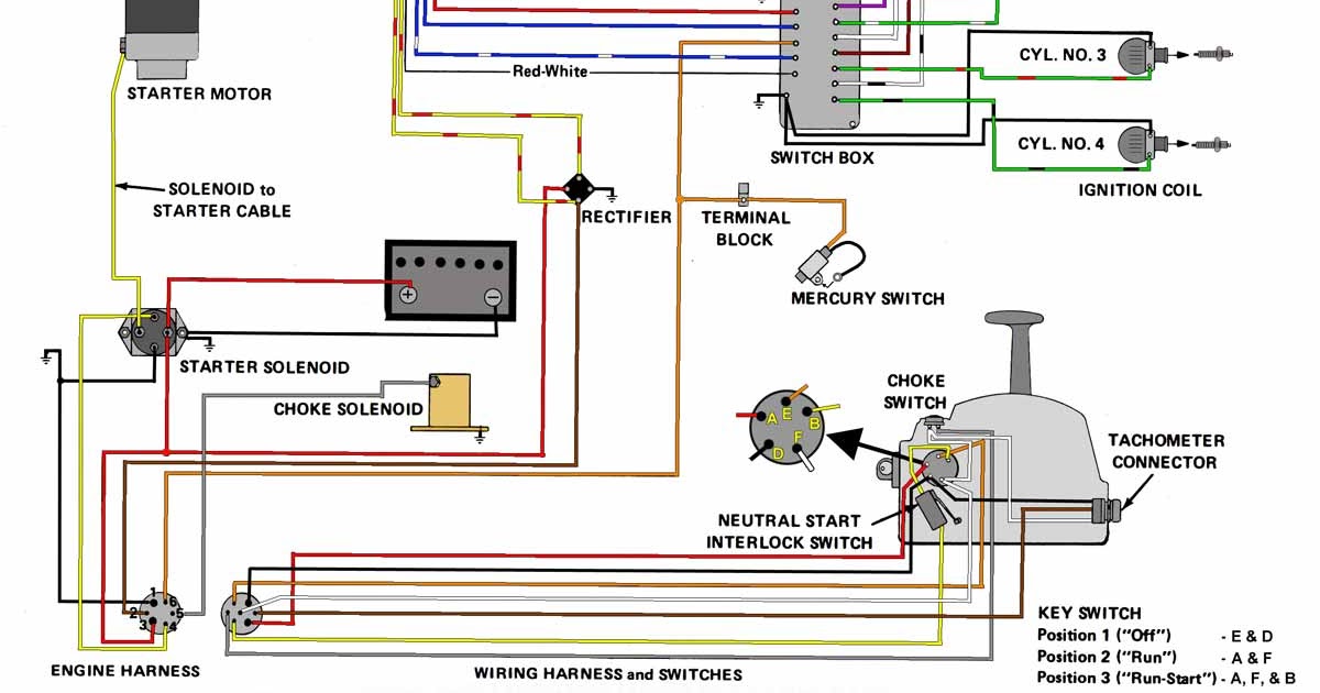
A wiring diagram for a Mercury ignition switch illustrates the electrical connections between various components in a Mercury vehicle’s ignition system. Each wire is identified by its color, gauge, and function, providing a clear visual representation of how the ignition switch interacts with other electrical systems.
Wiring diagrams are crucial for automotive technicians and enthusiasts alike. They enable comprehensive troubleshooting, system modification, and fault identification. Understanding the ignition switch wiring diagram is especially important for diagnosing and resolving ignition-related issues, ensuring smooth vehicle operation.
A key development in ignition switch design was the introduction of electronic ignition systems in the late 1960s. These systems replaced traditional mechanical contact points with electronic components, improving reliability and performance. The corresponding wiring diagrams evolved to reflect these technological advancements, becoming more complex but also offering greater functionality.
Wiring diagrams are essential for understanding, troubleshooting, and modifying electrical systems in Mercury vehicles. They provide a visual representation of the connections between the ignition switch and other electrical components, enabling technicians and enthusiasts to diagnose and resolve ignition-related issues.
- Components: Wiring diagrams identify all the components connected to the ignition switch, including the battery, starter, alternator, and ignition coil.
- Wiring: The diagrams show the color, gauge, and function of each wire, making it easy to trace and identify circuits.
- Connectors: Wiring diagrams indicate the location and type of connectors used to join wires, facilitating disassembly and reassembly.
- Grounding: The diagrams show how the ignition switch is grounded, which is crucial for proper electrical operation.
- Troubleshooting: Wiring diagrams enable technicians to systematically test and identify faulty components or connections.
- Modifications: When modifying an ignition system, wiring diagrams guide the addition or removal of components, ensuring compatibility and safety.
- Vehicle-specific: Each Mercury model has its own unique wiring diagram, accounting for variations in electrical systems.
- Electronic ignition: Modern Mercury vehicles use electronic ignition systems, which have more complex wiring diagrams reflecting the use of electronic components.
- Safety: Wiring diagrams are essential for ensuring the safe installation and operation of ignition systems, preventing electrical hazards.
- Documentation: Wiring diagrams are valuable documentation for vehicle owners and repair shops, providing a record of the ignition system’s electrical configuration.
These aspects collectively highlight the importance of wiring diagrams for Mercury ignition switches, enabling effective troubleshooting, modification, and maintenance of electrical systems.
Components
The identification of all components connected to the ignition switch is a critical aspect of wiring diagrams for Mercury ignition switches. These components play vital roles in the ignition and starting systems of the vehicle, and understanding their connections is essential for proper diagnosis, maintenance, and repair.
The battery provides the electrical power needed to start the vehicle and power its electrical systems. The starter motor uses this power to engage the engine’s flywheel and start the engine running. Once the engine is running, the alternator generates electricity to recharge the battery and power the vehicle’s electrical systems. The ignition coil is responsible for providing the high-voltage spark that ignites the air-fuel mixture in the engine’s cylinders, enabling combustion.
Wiring diagrams clearly illustrate the connections between the ignition switch and these components, showing how they interact to start and operate the vehicle. Without a proper wiring diagram, it would be difficult to trace and identify faulty connections or components, leading to potential problems with starting or operating the vehicle.
For example, if the starter motor is not receiving power when the ignition switch is turned to the “start” position, a wiring diagram can help identify whether the problem is a faulty connection, a blown fuse, or a malfunctioning ignition switch. Similarly, if the alternator is not charging the battery, a wiring diagram can guide the technician to check the connections between the alternator, battery, and ignition switch, as well as other components that may be involved in the charging system.
By understanding the components connected to the ignition switch and their connections as shown in wiring diagrams, automotive technicians and enthusiasts can effectively troubleshoot, repair, and modify the ignition system of Mercury vehicles, ensuring reliable and efficient operation.
Wiring
Within the context of a wiring diagram for a Mercury ignition switch, the identification of wire color, gauge, and function plays a crucial role in understanding and troubleshooting the ignition system. Wiring diagrams depict each wire with its respective color, thickness (gauge), and purpose, enabling technicians and enthusiasts to easily trace and identify circuits.
- Color Coding: Wires in a Mercury ignition system are color-coded to simplify identification and prevent confusion. Each color is assigned to a specific circuit or function, making it easier to trace wires throughout the system and identify their destinations.
- Gauge: The gauge of a wire refers to its thickness, which determines its current-carrying capacity. Wiring diagrams indicate the gauge of each wire, ensuring that the proper wire size is used for the intended application, preventing overheating or damage.
- Function Identification: Wiring diagrams clearly label the function of each wire, such as “starter solenoid,” “ignition coil,” or “power supply.” This information is critical for understanding the role of each wire in the ignition system and diagnosing potential issues.
- Circuit Tracing: The provision of wire color, gauge, and function allows technicians to trace circuits throughout the ignition system. By following the wires and their respective labels, they can identify open circuits, shorts, or other faults that may prevent the ignition system from functioning properly.
In summary, the identification of wire color, gauge, and function in wiring diagrams for Mercury ignition switches is essential for efficient diagnosis, repair, and modification of the ignition system. These elements provide a clear and concise representation of the electrical connections, enabling technicians to quickly trace circuits, identify faults, and ensure proper operation of the vehicle’s ignition system.
Connectors
In the context of “Wiring Diagram For Mercury Ignition Switch,” connectors play a crucial role in understanding the ignition system’s electrical connections. Wiring diagrams clearly indicate the location and type of connectors used to join wires, providing valuable information for disassembly, reassembly, and troubleshooting.
Connectors serve as critical components in the ignition system by establishing secure and reliable electrical connections between different wires. They enable the ignition switch to communicate with other electrical components, such as the starter, ignition coil, and battery. Without proper connectors, the electrical signals and power necessary for ignition would not be transmitted effectively.
Wiring diagrams provide detailed information about the type of connectors used, such as spade connectors, bullet connectors, or multi-pin connectors. This information helps technicians identify the correct replacement connectors when needed, ensuring proper fit and electrical continuity.
Furthermore, the indication of connector locations on wiring diagrams facilitates disassembly and reassembly during maintenance or repair. By understanding where connectors are located, technicians can quickly disconnect and reconnect wires without damaging the system or compromising its functionality.
In summary, the inclusion of connector information in wiring diagrams for Mercury ignition switches is essential for effective troubleshooting, repair, and maintenance. These diagrams provide a clear understanding of the ignition system’s electrical connections, enabling technicians to work efficiently and ensure the reliable operation of the vehicle’s ignition system.
Grounding
Within the context of “Wiring Diagram For Mercury Ignition Switch,” grounding plays a pivotal role in ensuring the proper functioning of the vehicle’s electrical system. Grounding refers to the electrical connection between a circuit and the chassis or frame of the vehicle, providing a common reference point for electrical current flow.
- Chassis Ground: The chassis of the vehicle serves as the primary grounding point for the ignition switch and other electrical components. This connection establishes a direct path for electrical current to flow back to the battery’s negative terminal, completing the circuit.
- Ground Wires: In addition to the chassis ground, dedicated ground wires are used to connect the ignition switch to specific grounding points on the vehicle’s body or engine. These wires ensure a reliable and low-resistance path for electrical current to return to the battery.
- Grounding Symbols: Wiring diagrams utilize specific symbols to represent grounding points and ground wires. Understanding these symbols is crucial for accurate interpretation of the diagram and proper troubleshooting.
- Importance of Proper Grounding: Without proper grounding, electrical circuits in the ignition system may not function correctly. Poor grounding can lead to voltage fluctuations, component malfunctions, and even electrical fires.
In summary, grounding is a fundamental aspect of the ignition system in Mercury vehicles. Wiring diagrams provide detailed information about the grounding points and ground wires, enabling technicians to understand the electrical connections and troubleshoot any grounding-related issues that may arise. Ensuring proper grounding is essential for the reliable and efficient operation of the vehicle’s electrical system.
Troubleshooting
Within the context of “Wiring Diagram For Mercury Ignition Switch,” troubleshooting is a crucial aspect of maintaining and repairing the vehicle’s electrical system. Wiring diagrams play a vital role in enabling technicians to systematically test and identify faulty components or connections, ensuring efficient and accurate troubleshooting.
The cause-and-effect relationship between troubleshooting and wiring diagrams is evident in the fact that wiring diagrams provide a visual representation of the electrical connections within the ignition switch system. This allows technicians to trace the flow of electricity and identify potential points of failure or malfunction. By understanding the intended electrical pathways as depicted in the wiring diagram, technicians can use testing equipment to measure voltage, continuity, and resistance, isolating the source of the problem.
For instance, if the vehicle exhibits ignition-related issues, such as difficulty starting or intermittent power loss, a wiring diagram guides the technician in testing the continuity of the circuit from the battery to the ignition switch, ignition coil, and spark plugs. By following the wiring diagram and conducting systematic tests, the technician can pinpoint the exact location of the fault, whether it’s a faulty wire, a loose connection, or a malfunctioning component.
The practical applications of this understanding extend to various scenarios. For example, in a situation where the vehicle’s starter motor fails to engage when the ignition key is turned, the wiring diagram helps the technician trace the circuit from the ignition switch to the starter solenoid. By testing the voltage and continuity along this path, the technician can determine if the problem lies in the ignition switch, the wiring, or the starter motor itself.
In conclusion, the connection between “Troubleshooting: Wiring diagrams enable technicians to systematically test and identify faulty components or connections” and “Wiring Diagram For Mercury Ignition Switch” is inseparable. Wiring diagrams provide the foundation for effective troubleshooting by illustrating the electrical connections within the ignition system. This understanding empowers technicians with the ability to diagnose and resolve ignition-related issues accurately, ensuring the reliable operation of the vehicle.
Modifications
Within the context of “Wiring Diagram For Mercury Ignition Switch,” modifications encompass alterations or upgrades to the vehicle’s ignition system. Wiring diagrams play a crucial role in ensuring the compatibility and safety of these modifications by guiding the addition or removal of components.
- Component Compatibility: Wiring diagrams provide a clear understanding of the electrical connections within the ignition system, enabling technicians to identify compatible components for upgrades or replacements. This compatibility ensures that the added or removed components work seamlessly with the existing system, preventing potential malfunctions or safety hazards.
- Circuit Protection: Wiring diagrams indicate the appropriate gauge and type of wires for each circuit, ensuring that the electrical system can handle the increased current draw or voltage requirements of modified components. This safeguards the electrical system from overloads and potential fires.
- Safety Features: Wiring diagrams often include details of safety features, such as fuses and relays, that protect the ignition system from electrical faults. Modifications may involve adding or relocating these safety components to maintain the system’s integrity and prevent damage to sensitive electronic components.
- Compliance with Regulations: In some regions, modifications to the ignition system must comply with specific regulations or standards. Wiring diagrams help ensure that modifications adhere to these regulations, preventing legal issues and maintaining the vehicle’s roadworthiness.
Overall, wiring diagrams are indispensable for safe and effective modifications to a Mercury ignition system, guiding technicians in selecting compatible components, ensuring proper circuit protection, incorporating safety features, and meeting regulatory requirements. They provide a visual roadmap for modifications, enabling technicians to confidently make changes to the ignition system while maintaining the vehicle’s reliability and safety.
Vehicle-specific
Within the context of “Wiring Diagram For Mercury Ignition Switch,” the aspect of vehicle-specificity highlights the unique electrical configurations found across different Mercury models. Wiring diagrams play a critical role in accommodating these variations, ensuring that the ignition system operates optimally in each model.
- Model-specific Components: Each Mercury model may incorporate unique components or features that require specific wiring configurations. For instance, models with advanced security systems or premium sound systems have additional electrical components that necessitate specialized wiring diagrams.
- Electrical System Variations: Different Mercury models may utilize distinct electrical system architectures, such as variations in voltage regulation, lighting systems, or CAN bus communication protocols. Wiring diagrams reflect these variations, providing the necessary information for technicians to understand and work on the specific electrical system of each model.
- Engine and Ignition System Differences: Variations in engine configurations, such as different engine sizes or fuel injection systems, can impact the wiring of the ignition system. Wiring diagrams account for these differences, ensuring that the ignition system is properly integrated with the engine and its electronic controls.
- Regional and Market Variations: Mercury vehicles may be sold in different regions or markets with specific electrical requirements or regulations. Wiring diagrams are tailored to meet these variations, ensuring compliance with local standards and regulations.
In conclusion, the vehicle-specific nature of wiring diagrams for Mercury ignition switches is crucial for ensuring compatibility and proper operation across the diverse range of Mercury models. These diagrams provide the necessary information for technicians to understand and work on the unique electrical configurations found in each model, ensuring reliable and efficient ignition system performance.
Electronic ignition
The advent of electronic ignition systems in modern Mercury vehicles has brought about a significant evolution in wiring diagrams for Mercury ignition switches. Electronic ignition systems utilize electronic components, such as sensors, modules, and microcontrollers, to control the ignition process, replacing the traditional mechanical contact points and distributor found in older vehicles.
This transition to electronic ignition has resulted in more complex wiring diagrams due to the increased number of electronic components and the intricate interconnections between them. These diagrams provide detailed information about the electronic components, their functions, and their connectivity within the ignition system.
For example, a wiring diagram for a Mercury vehicle with electronic ignition will include components such as the ignition control module, crankshaft position sensor, camshaft position sensor, and ignition coil. The diagram will show the connections between these components, as well as their power and ground connections.
Understanding these complex wiring diagrams is crucial for technicians and enthusiasts working on modern Mercury vehicles. It enables them to diagnose and troubleshoot ignition-related issues, modify the ignition system for performance enhancements, and maintain the vehicle’s electrical system effectively.
In summary, the use of electronic ignition systems in modern Mercury vehicles has a direct impact on the complexity of wiring diagrams for Mercury ignition switches. These diagrams provide a comprehensive representation of the electronic components and their interconnections, empowering technicians and enthusiasts to work on and maintain the vehicle’s ignition system efficiently.
Safety
Wiring diagrams play a pivotal role in ensuring the safe installation and operation of ignition systems in Mercury vehicles. They provide crucial information that helps prevent electrical hazards and potential safety risks.
Electrical hazards in ignition systems can arise from various factors, such as incorrect wiring, loose connections, or faulty components. Wiring diagrams serve as a comprehensive guide for technicians and enthusiasts, enabling them to understand the proper installation and maintenance procedures for the ignition system.
For instance, a wiring diagram clearly outlines the correct wire colors, gauges, and connection points for each component within the ignition system. This information ensures that the system is assembled correctly, minimizing the risk of short circuits, electrical fires, or other hazards.
Furthermore, wiring diagrams provide insights into the electrical load and power distribution within the ignition system. By understanding the current and voltage requirements of each component, technicians can select appropriate wires and fuses to prevent overloading and potential electrical failures.
In summary, wiring diagrams are indispensable for ensuring the safe installation and operation of ignition systems in Mercury vehicles. They provide detailed instructions and guidance, empowering technicians and enthusiasts to work on the ignition system with confidence, minimizing the risk of electrical hazards and maintaining the vehicle’s overall safety.
Documentation
Wiring diagrams serve as indispensable documentation for both vehicle owners and repair shops, providing a detailed record of the ignition system’s electrical configuration. This comprehensive documentation plays a critical role in maintaining and troubleshooting the ignition system throughout the vehicle’s lifespan.
For vehicle owners, wiring diagrams empower them with the knowledge to perform basic maintenance and repairs on their own. By referencing the wiring diagram, they can identify and replace faulty components, such as spark plugs or ignition coils, ensuring the smooth operation of the ignition system.
For repair shops, wiring diagrams are an essential tool for diagnosing and resolving complex ignition-related issues. The detailed schematics allow technicians to trace circuits, identify potential problems, and determine the root cause of malfunctions. This accurate and efficient troubleshooting process minimizes downtime and repair costs for vehicle owners.
Furthermore, wiring diagrams serve as a valuable reference for modifications and upgrades to the ignition system. Whether it’s installing a performance ignition coil or integrating additional electrical components, the wiring diagram provides a clear understanding of the system’s architecture, enabling informed decision-making and safe implementation of modifications.
In conclusion, wiring diagrams are not merely technical documents but essential tools for understanding, maintaining, and modifying the ignition system in Mercury vehicles. Their role as valuable documentation empowers vehicle owners and repair shops with the knowledge and guidance necessary to ensure the reliable and efficient operation of the ignition system.


Related Posts


