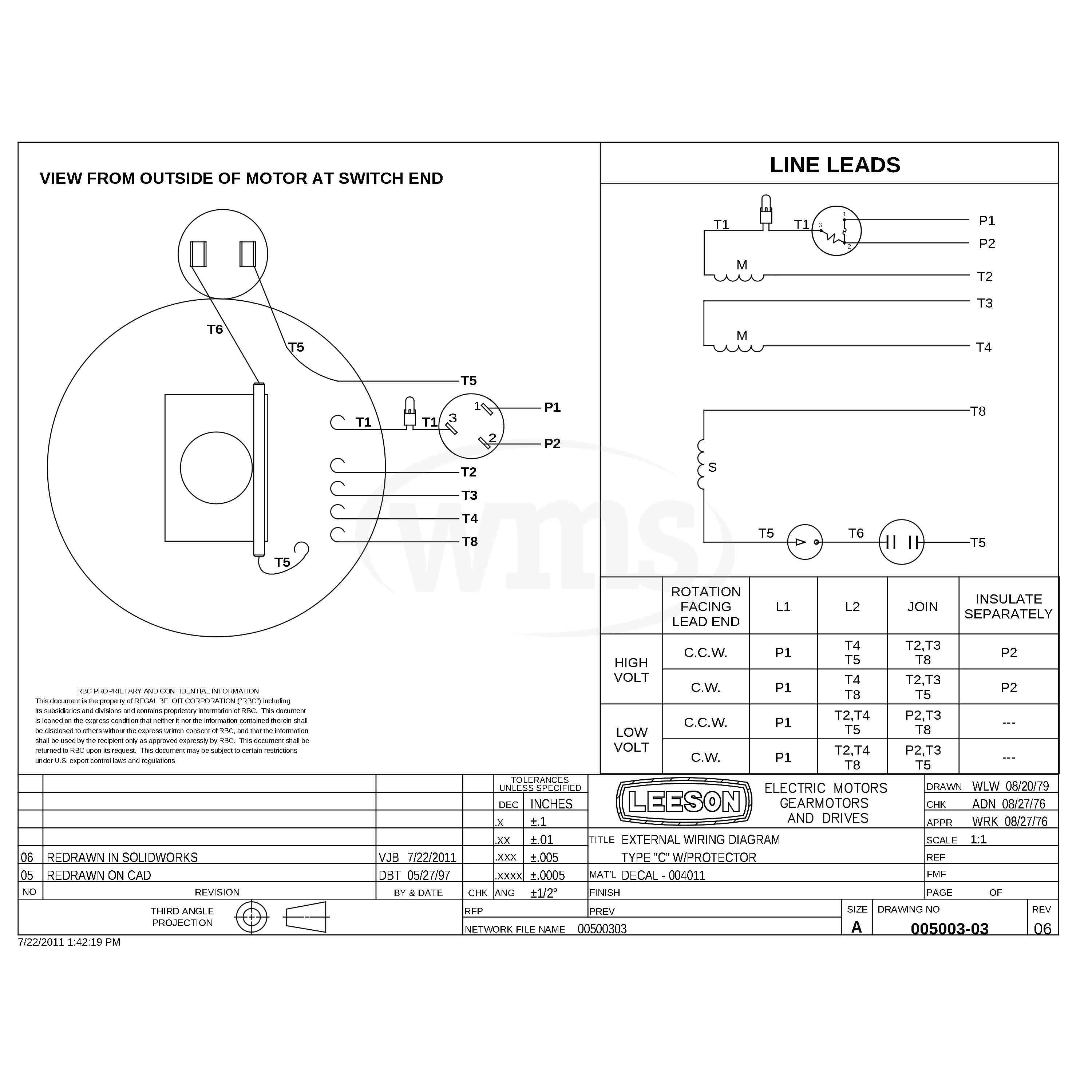
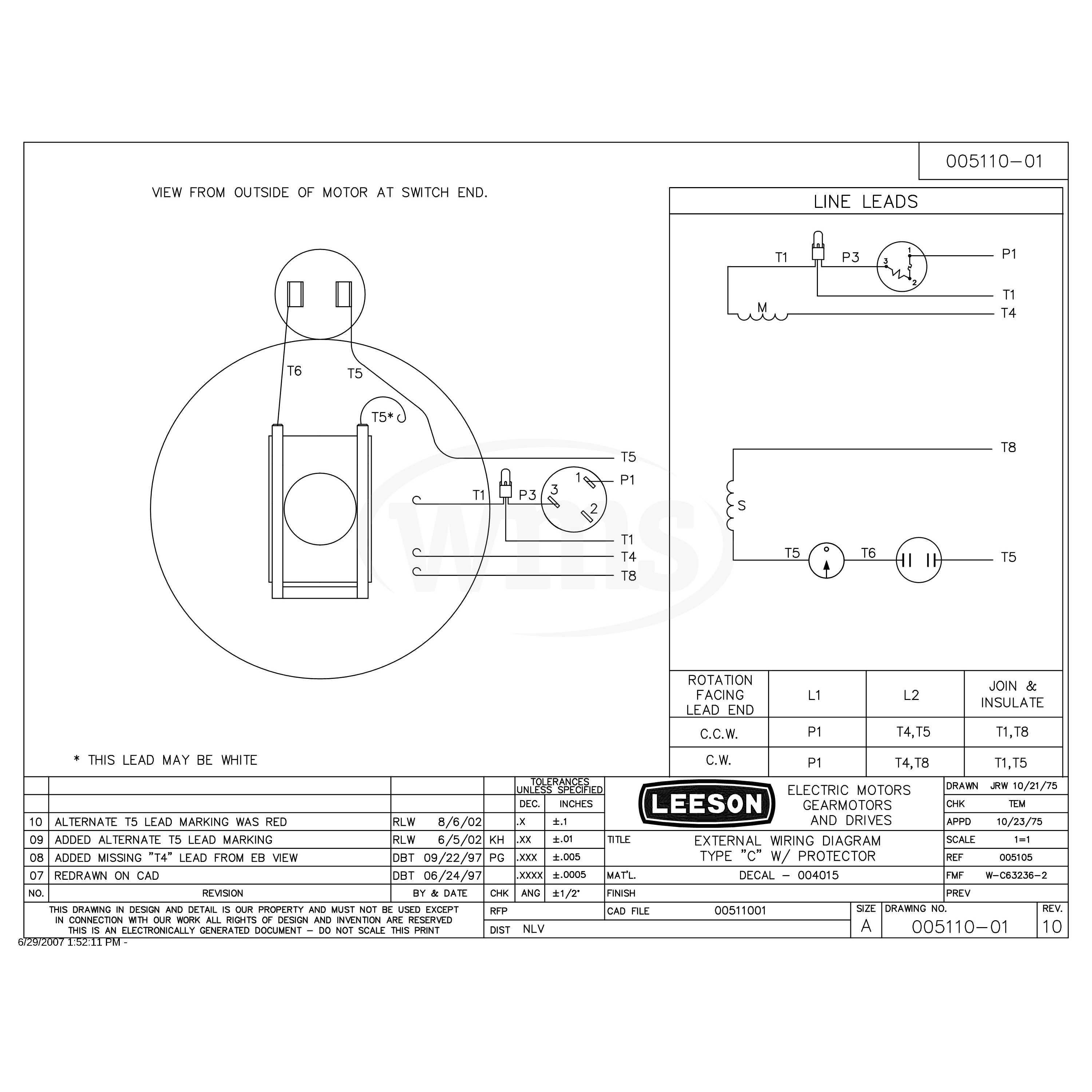
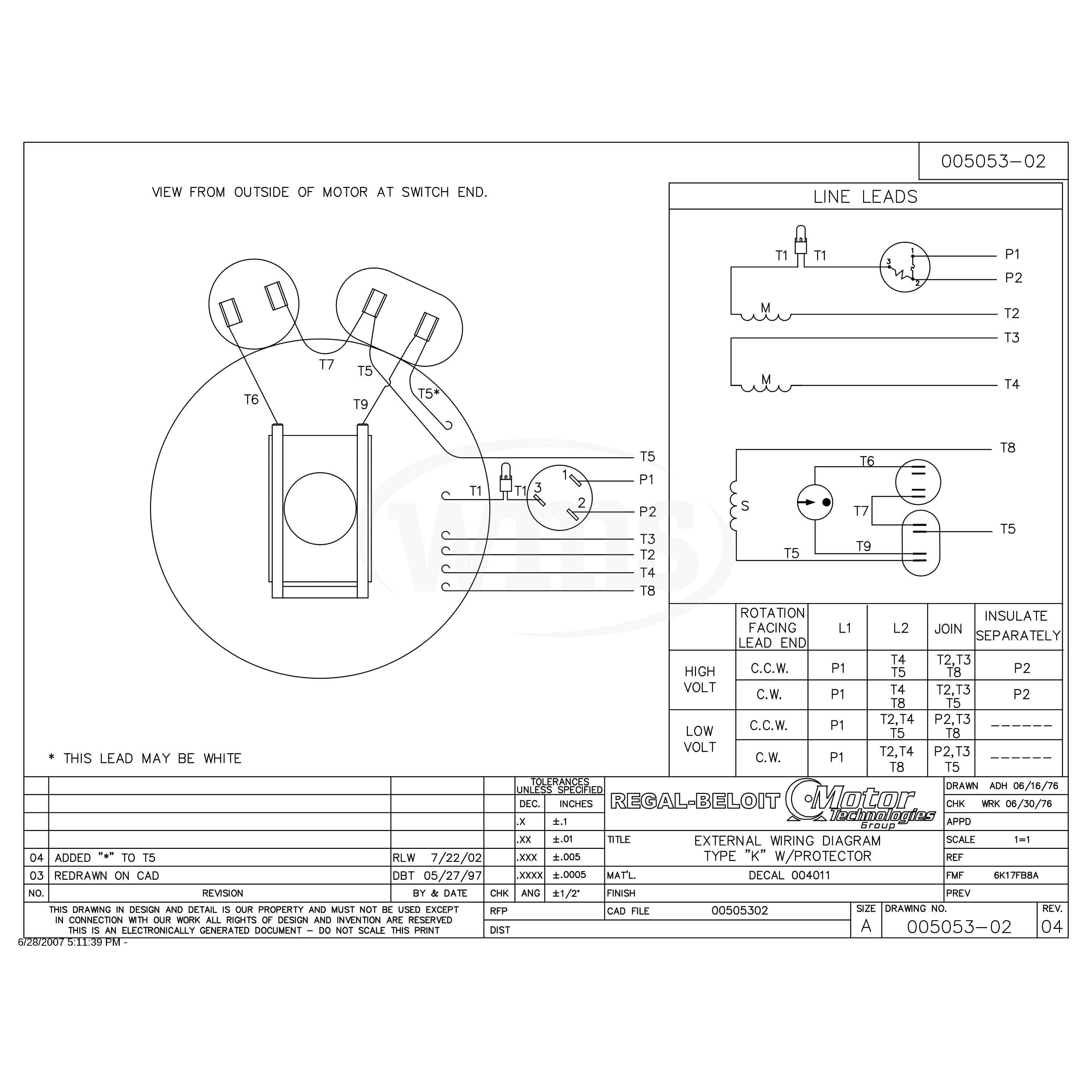
A Wiring Diagram for Leeson Electric Motors provides detailed instructions and guidance for connecting and configuring Leeson electric motors. It outlines the proper electrical connections between the motor’s terminals, power source, and any necessary control devices or accessories.
Wiring Diagrams for Leeson Electric Motors are essential for ensuring the safe and efficient operation of the motor. They help prevent electrical hazards, ensure proper functionality, and optimize the motor’s performance. They are widely used in various industrial and commercial applications where Leeson motors are employed, such as conveyor systems, pumps, and manufacturing machinery.
One significant historical development in Wiring Diagrams for Leeson Electric Motors was the introduction of computerized design and drafting software. This advancement allowed for the creation of more accurate and detailed diagrams, reducing the risk of errors and improving the overall quality of the diagrams.
Wiring Diagrams for Leeson Electric Motors play a crucial role in the electrical installation and maintenance of these motors. They provide essential information for understanding the motor’s electrical connections and ensuring its safe and efficient operation.
- Accuracy: Precise wiring diagrams ensure that the motor is connected correctly, preventing electrical hazards and malfunctions.
- Clarity: Clear and well-organized diagrams make it easy for electricians to understand the motor’s wiring, reducing installation time and errors.
- Safety: Wiring diagrams help prevent electrical accidents by providing instructions for proper grounding and protection against overloads.
- Efficiency: Correct wiring ensures that the motor operates at its optimal efficiency, reducing energy consumption and extending its lifespan.
- Troubleshooting: Wiring diagrams assist in troubleshooting electrical issues by providing a visual representation of the motor’s connections.
- Maintenance: Regular maintenance is crucial for motor longevity. Wiring diagrams guide maintenance personnel in inspecting and servicing the motor’s electrical components.
- Compliance: Wiring diagrams help ensure compliance with electrical codes and standards, reducing the risk of legal liabilities.
- Customization: Wiring diagrams can be customized to accommodate specific motor configurations and application requirements.
These aspects collectively highlight the importance of Wiring Diagrams for Leeson Electric Motors in ensuring the safety, efficiency, and reliability of these motors in various industrial and commercial applications.
Accuracy
In the context of Wiring Diagrams for Leeson Electric Motors, accuracy is of paramount importance. Precise wiring diagrams provide detailed instructions for connecting the motor to the power source and any necessary control devices. By ensuring that the motor is connected correctly, these diagrams prevent electrical hazards and malfunctions that could lead to equipment damage, downtime, and safety risks.
For instance, incorrect wiring can result in short circuits, which can cause overheating and fires. Improper grounding can lead to electrical shocks or damage to the motor itself. Accurate wiring diagrams help to mitigate these risks by providing clear instructions for proper connections.
The practical significance of accurate wiring diagrams extends to various industrial and commercial applications. In manufacturing facilities, they ensure the safe and efficient operation of conveyor systems, pumps, and other machinery powered by Leeson electric motors. In commercial buildings, they contribute to the reliable functioning of HVAC systems, elevators, and other electrical equipment.
In summary, accurate Wiring Diagrams for Leeson Electric Motors play a critical role in preventing electrical hazards and malfunctions. They provide precise instructions for connecting the motor correctly, ensuring its safe and efficient operation in a wide range of applications.
Clarity
Within the broader context of Wiring Diagrams for Leeson Electric Motors, clarity plays a crucial role in ensuring efficient and error-free installation and maintenance. Clear and well-organized diagrams provide electricians with a comprehensive visual representation of the motor’s electrical connections, enabling them to quickly and accurately understand the wiring configuration.
- Symbol Standardization: Wiring diagrams for Leeson electric motors adhere to standardized symbols and conventions, ensuring that electricians familiar with industry practices can easily interpret the diagrams. This standardization reduces confusion and the risk of misinterpreting connections.
- Color-Coding: Many wiring diagrams use color-coding to differentiate between different types of wires and connections. This visual cue helps electricians quickly identify and trace wires, reducing installation time and the likelihood of errors.
- Logical Layout: Clear wiring diagrams follow a logical layout, with connections and components arranged in a way that reflects the physical layout of the motor. This logical arrangement makes it easier for electricians to follow the diagram and identify the corresponding connections on the motor.
- Detailed Annotations: In addition to visual representations, wiring diagrams often include detailed annotations and labels. These annotations provide additional information about the function of each connection, the type of wire required, and any special considerations.
Overall, clear and well-organized wiring diagrams for Leeson electric motors are essential for efficient and accurate electrical installations. They provide electricians with a comprehensive visual guide to the motor’s wiring configuration, reducing installation time, minimizing errors, and ensuring the safe and reliable operation of the motor.
Safety
Within the context of Wiring Diagrams for Leeson Electric Motors, safety is paramount. These diagrams provide detailed instructions for proper grounding and protection against overloads, safeguarding against electrical accidents and ensuring the safe operation of the motor.
Grounding is essential for electrical safety as it provides a low-resistance path for fault currents to flow back to the source, preventing dangerous voltages from building up on the motor’s frame or other components. Wiring diagrams clearly indicate the grounding points on the motor and specify the appropriate grounding wire size and connection methods.
Overload protection is crucial to prevent damage to the motor caused by excessive current draw. Wiring diagrams provide guidance on selecting and installing overload protection devices, such as fuses or circuit breakers, that will trip when the current exceeds a safe level, disconnecting the motor from the power source.
Real-life examples of how Wiring Diagrams for Leeson Electric Motors contribute to safety include:
- In a manufacturing facility, a properly grounded motor prevents electrical shocks to personnel who may come into contact with the motor’s frame.
- In a commercial building, an overload protection device installed based on the wiring diagram’s instructions safeguards the motor from damage during a power surge.
The practical significance of understanding the connection between safety and Wiring Diagrams for Leeson Electric Motors lies in ensuring the safe installation, operation, and maintenance of these motors. By following the instructions provided in these diagrams, electricians and maintenance personnel can minimize the risk of electrical accidents, protect equipment, and maintain a safe working environment.
In summary, Wiring Diagrams for Leeson Electric Motors play a critical role in preventing electrical accidents by providing clear instructions for proper grounding and protection against overloads. These diagrams are essential for ensuring the safe and reliable operation of Leeson electric motors in various industrial and commercial applications.
Efficiency
Within the broader context of Wiring Diagrams for Leeson Electric Motors, efficiency stands as a crucial factor in ensuring the optimal performance and longevity of these motors. Correct wiring practices play a pivotal role in achieving this efficiency, leading to reduced energy consumption and extended motor lifespan.
- Reduced Energy Consumption: Properly wired motors operate at their optimal efficiency, minimizing energy losses and reducing overall energy consumption. This translates into lower operating costs and a positive impact on the environment.
- Lower Operating Temperatures: Efficient wiring ensures that the motor operates within its designed temperature range, reducing the risk of overheating and premature component failure. Lower operating temperatures contribute to extended motor lifespan.
- Improved Power Factor: Correct wiring helps maintain a high power factor, which is a measure of how effectively the motor converts electrical energy into mechanical energy. A high power factor reduces energy losses and improves the motor’s overall efficiency.
- Reduced Maintenance Costs: Efficiently wired motors require less maintenance due to reduced wear and tear on components. This translates into lower maintenance costs and increased uptime for the motor.
The implications of correct wiring on the efficiency of Leeson electric motors are far-reaching. In industrial settings, efficient motors contribute to reduced energy consumption and operating costs for businesses. In commercial buildings, they play a role in achieving energy efficiency goals and creating a more sustainable environment. Across various applications, properly wired motors enhance productivity, minimize downtime, and extend the lifespan of these essential electrical components.
Troubleshooting
Within the comprehensive framework of Wiring Diagrams for Leeson Electric Motors, troubleshooting plays a crucial role in maintaining the optimal performance and longevity of these motors. Wiring diagrams serve as invaluable tools in diagnosing and resolving electrical issues, ensuring the efficient operation of motors in various industrial and commercial applications.
- Identification of Faulty Components: Wiring diagrams provide a visual representation of the motor’s electrical connections, enabling technicians to quickly identify faulty components by comparing the actual wiring configuration to the diagram. This targeted approach minimizes downtime and facilitates timely repairs.
- Tracing Electrical Paths: Troubleshooting often involves tracing electrical paths to locate the source of an issue. Wiring diagrams act as a roadmap, guiding technicians through the motor’s electrical system and helping them identify points of failure or interruption.
- Analysis of Circuit Behavior: By studying the wiring diagram, technicians can analyze the behavior of electrical circuits within the motor. This analysis helps them understand the flow of current and identify potential problems, such as overloads or ground faults.
- Verification of Repairs: After repairs have been made, wiring diagrams assist in verifying the correct restoration of electrical connections. By comparing the actual wiring configuration to the diagram, technicians can ensure that the repairs have been executed properly, reducing the risk of further issues.
In summary, the troubleshooting aspect of Wiring Diagrams for Leeson Electric Motors is indispensable for maintaining the reliable operation of these motors. By providing a visual representation of the motor’s electrical connections, wiring diagrams empower technicians to efficiently identify faulty components, trace electrical paths, analyze circuit behavior, and verify repairs. These capabilities contribute to reduced downtime, increased productivity, and extended motor lifespan.
Maintenance
Within the comprehensive framework of Wiring Diagrams for Leeson Electric Motors, maintenance plays a pivotal role in ensuring optimal performance and extending the lifespan of these motors. Wiring diagrams serve as indispensable tools for maintenance personnel, providing detailed guidance for inspecting and servicing the motor’s electrical components.
- Inspection and Cleaning: Wiring diagrams assist maintenance personnel in visually inspecting electrical connections, terminals, and other components for signs of damage, corrosion, or loose connections. Regular cleaning of electrical components, as indicated in the wiring diagram, helps prevent the accumulation of dust and debris that can interfere with proper operation.
- Component Replacement: Wiring diagrams guide maintenance personnel in identifying and replacing faulty electrical components. By referencing the diagram, technicians can accurately determine the type and specifications of replacement components, ensuring compatibility with the motor.
- Troubleshooting Electrical Issues: Wiring diagrams provide a roadmap for troubleshooting electrical issues within the motor. By tracing electrical paths and analyzing circuit behavior, maintenance personnel can pinpoint the source of problems and make necessary repairs or adjustments.
- Predictive Maintenance: Wiring diagrams enable maintenance personnel to perform predictive maintenance by monitoring the condition of electrical components and identifying potential issues before they lead to failures. Regular inspections and testing, guided by the wiring diagram, help prevent unexpected downtime and extend the motor’s lifespan.
In summary, the maintenance aspect of Wiring Diagrams for Leeson Electric Motors is crucial for maintaining the reliable operation of these motors throughout their service life. By providing a visual representation of the motor’s electrical connections, wiring diagrams empower maintenance personnel to effectively inspect, service, and troubleshoot electrical components. This contributes to reduced downtime, increased productivity, and extended motor lifespan.
Compliance
Within the comprehensive framework of Wiring Diagrams for Leeson Electric Motors, compliance with electrical codes and standards stands as a critical aspect of ensuring safety, reliability, and legal adherence. Wiring diagrams play a pivotal role in achieving this compliance, mitigating the risk of legal liabilities and safeguarding against electrical hazards.
- Adherence to Safety Regulations: Wiring diagrams guide the installation and maintenance of Leeson electric motors in accordance with established electrical codes and standards. These codes and standards are designed to minimize the risk of electrical fires, shocks, and other hazards, ensuring the safety of personnel and the integrity of electrical systems.
- Prevention of Code Violations: By following the instructions provided in wiring diagrams, electricians and maintenance technicians can avoid violations of electrical codes. Code violations can lead to fines, penalties, and even legal action, jeopardizing the reputation and financial standing of businesses.
- Protection Against Electrical Hazards: Properly wired motors, as per the specifications outlined in wiring diagrams, reduce the likelihood of electrical accidents and injuries. This proactive approach safeguards personnel from potential harm and minimizes the risk of costly insurance claims or legal disputes.
- Insurance and Legal Compliance: Insurance companies often require businesses to demonstrate compliance with electrical codes and standards as a condition for coverage. Wiring diagrams serve as documented proof of proper installation and maintenance, facilitating insurance approvals and reducing the risk of legal complications in the event of an electrical incident.
In summary, the compliance aspect of Wiring Diagrams for Leeson Electric Motors is paramount for ensuring the safety and reliability of electrical installations. By adhering to electrical codes and standards, these diagrams help businesses mitigate the risk of legal liabilities, protect personnel from electrical hazards, and maintain compliance with insurance requirements. Wiring diagrams play a vital role in safeguarding electrical systems, upholding legal obligations, and fostering a culture of safety and compliance.
Customization
Within the comprehensive framework of “Wiring Diagram for Leeson Electric Motors”, customization plays a pivotal role in tailoring electrical installations to meet specific motor configurations and application requirements. This flexibility allows for optimal performance, enhanced safety, and efficient operation in diverse industrial and commercial settings.
- Motor Type and Configuration: Wiring diagrams can be customized to accommodate different types of Leeson electric motors, including single-phase, three-phase, and DC motors. They also provide guidance for specific motor configurations, such as reversing motors, brake motors, and explosion-proof motors.
- Control and Protection Devices: Customization extends to the integration of various control and protection devices. Wiring diagrams can incorporate contactors, relays, overload protectors, and other components to suit the specific control and protection requirements of the application.
- Environmental Conditions: Wiring diagrams can be tailored to account for environmental conditions, such as high temperatures, humidity, or corrosive atmospheres. This customization ensures that the wiring is appropriate for the intended operating environment and minimizes the risk of electrical hazards.
- Special Applications: Customization also caters to unique application requirements. For example, wiring diagrams can be modified to accommodate motors used in hazardous locations, medical equipment, or renewable energy systems.
The customization aspect of “Wiring Diagram for Leeson Electric Motors” offers numerous advantages. It enables engineers and electricians to design electrical systems that precisely match the performance and safety demands of the application. This tailored approach enhances the efficiency, reliability, and longevity of the motors while ensuring compliance with industry standards and regulations.


Related Posts


