A wiring diagram for John Deere L110 is an invaluable tool for understanding the electrical system of this popular lawn tractor. It provides a visual representation of the electrical connections between various components, allowing users to troubleshoot and repair electrical issues efficiently.
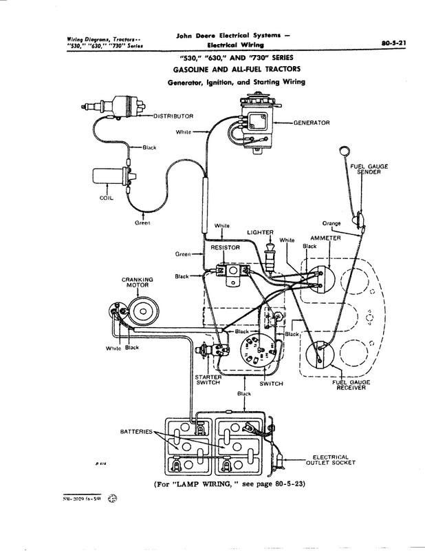
The wiring diagram outlines the flow of electricity from the battery to the starter, ignition system, lighting, and other accessories. By referring to the diagram, users can quickly identify the location of wires, connectors, relays, and fuses, making it easier to diagnose and resolve electrical problems.
Wiring diagrams have been used in various industries for decades, becoming an essential tool for maintaining and repairing electrical systems. They have significantly improved the safety and reliability of electrical equipment, enabling technicians to quickly and accurately identify and resolve electrical faults.
For a “Wiring Diagram for John Deere L110”, several key aspects are crucial to understand:
- Circuit Layout: The diagram provides a clear layout of all electrical circuits within the L110, including their pathways and connections.
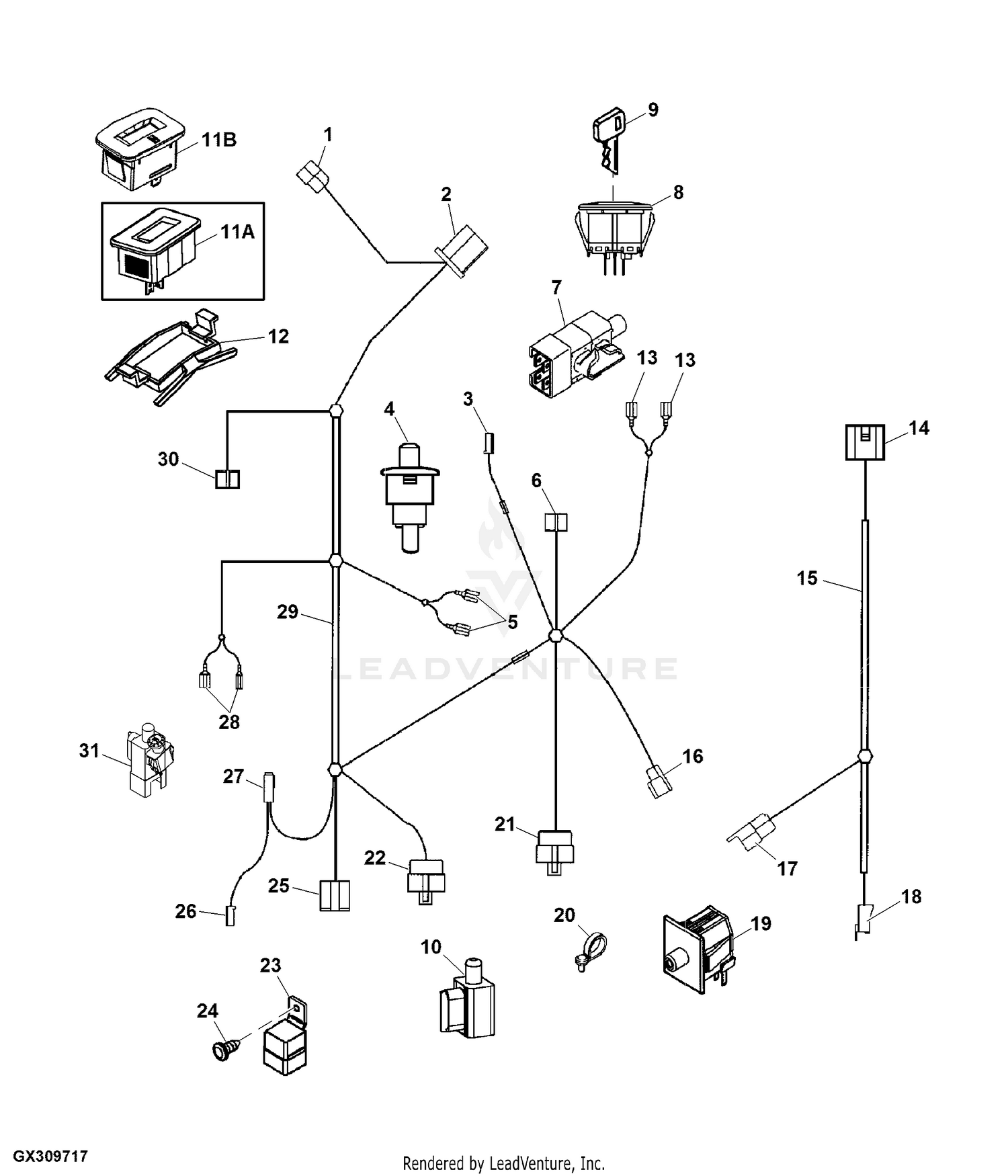
- Component Identification: It helps identify and locate various electrical components, such as relays, fuses, switches, and sensors.
- Wire Color Coding: The diagram uses color coding to differentiate wires for easy identification and tracing.
- Connector Types: It illustrates the types of connectors used in the electrical system, aiding in proper connection and repair.
- Grounding Points: The diagram indicates appropriate grounding points for electrical components, ensuring proper grounding and preventing electrical hazards.
- Testing Points: It identifies test points for voltage and continuity checks, facilitating electrical troubleshooting.
- Power Distribution: The diagram shows how power is distributed from the battery to various components, aiding in understanding the system’s power flow.
- Fuse and Relay Locations: It provides the locations of fuses and relays, making it easier to identify and replace blown or faulty components.
- Troubleshooting Guide: Some diagrams include troubleshooting guides that assist in diagnosing and resolving common electrical issues.
- Compliance with Standards: The diagram ensures compliance with electrical standards and regulations, promoting safety and reliability.
These aspects are essential for effectively using a wiring diagram for the John Deere L110. They enable technicians and users to accurately diagnose, repair, and maintain the electrical system, ensuring optimal performance and safety.
Circuit Layout
The circuit layout is a crucial aspect of the wiring diagram for John Deere L110. It offers a comprehensive visual representation of the electrical circuitry, enabling users to understand how various components interconnect and function within the system.
- Circuit Identification: The diagram clearly labels and identifies each electrical circuit, such as the ignition circuit, lighting circuit, and charging circuit, making it easy to trace and troubleshoot specific circuits.
- Pathway Visualization: It provides a graphical representation of the pathways taken by electrical current through the system. This helps users visualize the flow of electricity and identify potential points of failure.
- Component Locations: The diagram indicates the physical locations of electrical components, such as relays, fuses, switches, and sensors, within the L110. This allows users to quickly locate and access components for maintenance or repair.
- Grounding Points: The diagram specifies the designated grounding points for the electrical system. Proper grounding is essential for safety and preventing electrical hazards, and the diagram ensures that grounding is correctly implemented.
Understanding the circuit layout is fundamental for effectively using a wiring diagram for the John Deere L110. It empowers users to diagnose electrical issues accurately, perform repairs efficiently, and maintain the electrical system safely, ensuring optimal performance and longevity of the lawn tractor.
Component Identification
Component identification is a critical aspect of a wiring diagram for John Deere L110, enabling users to understand the system’s electrical components and their locations. A wiring diagram provides a visual representation of the electrical circuitry, but without proper component identification, it becomes difficult to interpret and utilize the diagram effectively.
Electrical components, such as relays, fuses, switches, and sensors, play vital roles in the proper functioning of the L110’s electrical system. Relays control the flow of electricity to various circuits, fuses protect against electrical overloads, switches allow users to control electrical devices, and sensors monitor system parameters and provide feedback to the electronic control unit (ECU).
By identifying and locating these components using the wiring diagram, users can perform maintenance, troubleshooting, and repairs more efficiently. For instance, if a fuse blows, the wiring diagram helps identify the location of the blown fuse, allowing for quick replacement and restoration of power to the affected circuit.
Furthermore, component identification aids in tracing electrical faults and diagnosing system malfunctions. By understanding the connections between components, users can systematically check for continuity, voltage, and grounding issues, leading to accurate problem identification and resolution.
Overall, component identification is a fundamental element of a wiring diagram for John Deere L110, providing users with the ability to comprehend the electrical system, perform maintenance and troubleshooting, and ensure the safe and efficient operation of the lawn tractor.
Wire Color Coding
Wire color coding is a crucial component of a wiring diagram for John Deere L110, enabling efficient troubleshooting and maintenance of its electrical system. The use of color coding in the diagram provides several advantages:
Simplified Identification: By assigning unique colors to different wires, the diagram makes it easier to identify and trace specific wires within the complex electrical system of the L110. This simplifies the process of locating and repairing faulty wires or diagnosing electrical issues.
Circuit Differentiation: Color coding helps differentiate between different electrical circuits, allowing users to quickly identify which wires belong to a particular circuit. This is especially useful when multiple circuits are bundled together or when tracing wires through tight spaces.
Wiring Consistency: Color coding ensures consistency in electrical wiring, reducing the risk of errors during installation or repair. By following the color scheme specified in the diagram, users can ensure that wires are connected correctly, preventing short circuits and potential damage to the electrical system.
Real-Life Example: In a practical scenario, suppose the headlight of the L110 is not working. Using the wiring diagram, a technician can quickly identify the wires responsible for powering the headlight by referring to their color coding. This allows the technician to trace the wires, check for any breaks or loose connections, and resolve the issue efficiently.
Understanding wire color coding is essential for effectively using a wiring diagram for John Deere L110. It enables users to accurately identify and trace wires, troubleshoot electrical problems, and maintain the electrical system safely and efficiently, ensuring optimal performance and longevity of the lawn tractor.
Connector Types
In the context of “Wiring Diagram for John Deere L110,” the aspect of “Connector Types” plays a pivotal role in understanding and maintaining the electrical system. Connectors are essential components that facilitate secure and reliable electrical connections between various components, ensuring proper functioning of the lawn tractor.
- Types of Connectors: The diagram identifies and illustrates different types of connectors used in the L110’s electrical system, including bullet connectors, spade connectors, ring terminals, and multi-pin connectors. Each type is designed for a specific purpose and application.
- Wiring Harness: The diagram provides insights into the wiring harness, which houses and organizes multiple wires and connectors. Understanding the layout and connections within the wiring harness is crucial for efficient troubleshooting and repair.
- Connector Compatibility: The diagram ensures that connectors are compatible with their respective components. It specifies the appropriate connector types for each electrical component, preventing mismatches and ensuring reliable connections.
- Real-Life Example: Suppose the taillight of the L110 is not working. By referring to the wiring diagram and identifying the type of connector used for the taillight, a technician can quickly check the connection, clean or replace the connector if necessary, and restore functionality.
Understanding connector types is essential for effectively using a wiring diagram for John Deere L110. It enables users to correctly identify, connect, and repair electrical components, ensuring reliable operation and preventing electrical faults. By providing detailed information about connector types, the wiring diagram empowers users to maintain and troubleshoot the electrical system with confidence, extending the lifespan and safety of the lawn tractor.
Grounding Points
Grounding points are crucial in electrical systems as they provide a path for excess electrical current to safely dissipate into the ground, preventing shocks, fires, and damage to equipment. In the context of a “Wiring Diagram for John Deere L110,” grounding points are an essential component, ensuring the safe and reliable operation of the lawn tractor.
The diagram serves as a guide for technicians and users to identify and connect electrical components to appropriate grounding points. By following the diagram, they can ensure that all components are properly grounded, minimizing the risk of electrical hazards.
For instance, if the engine block of the L110 is not properly grounded, it could lead to electrical imbalances, causing components to malfunction or even posing a safety risk. The wiring diagram provides clear instructions on the grounding point for the engine block, ensuring proper grounding and preventing such issues.
Understanding grounding points is essential for using a wiring diagram for the John Deere L110 effectively. It empowers users to maintain and troubleshoot the electrical system safely, preventing electrical faults and extending the lifespan of the lawn tractor.
Testing Points
In the context of “Wiring Diagram for John Deere L110,” testing points play a crucial role in assisting technicians and users in diagnosing and resolving electrical issues. The diagram provides clear indications of designated test points, enabling quick and accurate voltage and continuity checks, which are essential for effective troubleshooting.
- Voltage Check Points: The diagram identifies specific points in the electrical system where voltage can be measured. This allows users to verify the presence and level of voltage at various points, helping them isolate potential issues related to power supply or voltage drops.
- Continuity Check Points: The diagram also indicates points where continuity can be tested. This helps users determine if there is a complete electrical pathway between two points, ensuring proper circuit operation. Continuity checks are crucial for identifying breaks or faults in wires, connectors, and components.
- Grounding Points: Additionally, the diagram provides test points for checking grounding connections. Proper grounding is essential for safety and preventing electrical hazards. By testing grounding points, users can ensure that components are correctly grounded.
- Real-Life Example: Suppose the battery of the L110 is not charging properly. Using a multimeter, a technician can test the voltage at the battery terminals and at designated test points along the charging circuit. This helps identify if the problem lies in the battery itself, the charging system, or a faulty connection.
Understanding the significance of testing points in a wiring diagram empowers users to perform electrical diagnostics efficiently. By utilizing these test points, they can pinpoint electrical faults accurately, reducing downtime and ensuring the safe and reliable operation of the John Deere L110 lawn tractor.
Power Distribution
In the context of a “Wiring Diagram for John Deere L110,” power distribution plays a fundamental role in understanding how electrical power flows within the lawn tractor’s system. The diagram serves as a visual guide, providing insights into the pathways and connections through which power is distributed from the battery to various components.
Understanding power distribution is crucial because it enables users to:
- Identify Power Sources: The diagram helps identify the primary power source (typically the battery) and any secondary or backup power sources.
- Trace Power Flow: By following the diagram, users can trace the flow of power from the battery to different components, such as the ignition system, lighting, accessories, and sensors.
- Diagnose Electrical Issues: By understanding the power distribution network, users can pinpoint potential points of failure or interruptions, aiding in diagnosing electrical issues more efficiently.
For instance, if the headlights of the L110 are not working, a technician can refer to the wiring diagram to trace the power distribution path to the headlights. This allows them to check for loose connections, blown fuses, or faulty wiring, enabling targeted troubleshooting and repairs.
Furthermore, understanding power distribution is essential for modifications or upgrades to the electrical system. By knowing how power is distributed, users can determine the appropriate power requirements for additional components, ensuring compatibility and preventing overloading or damage to the system.
In summary, power distribution is a critical aspect of a wiring diagram for John Deere L110, providing valuable insights into the flow of electrical power within the system. By understanding power distribution, users can effectively troubleshoot electrical issues, perform modifications, and maintain the optimal functioning of their lawn tractor.
Fuse and Relay Locations
In the context of a “Wiring Diagram for John Deere L110,” the section on “Fuse and Relay Locations” holds critical importance, establishing a direct connection between the diagram and the efficient maintenance and repair of the lawn tractor’s electrical system.
Fuses and relays play vital roles in protecting electrical circuits and components from damage caused by overcurrent or short circuits. Identifying and replacing blown or faulty fuses and relays is crucial for restoring proper electrical function and preventing further damage to the electrical system.
The wiring diagram serves as an invaluable tool by providing precise locations for fuses and relays within the L110’s electrical system. By referring to the diagram, users can quickly pinpoint the location of a blown fuse or faulty relay, enabling prompt replacement and restoration of electrical power to affected components.
For instance, if the L110’s headlights are not working, a technician can use the wiring diagram to locate the fuse responsible for the headlight circuit. By inspecting and replacing the blown fuse, the technician can restore power to the headlights, ensuring safe operation during nighttime or low-visibility conditions.
Understanding the significance of fuse and relay locations empowers users to maintain and troubleshoot the L110’s electrical system proactively. By regularly inspecting and replacing fuses and relays as needed, users can prevent electrical malfunctions, extend the lifespan of electrical components, and ensure the safe and reliable operation of their lawn tractor.
Troubleshooting Guide
Within the context of “Wiring Diagram for John Deere L110,” the inclusion of a troubleshooting guide holds significant value and establishes a direct connection between the diagram and the efficient maintenance and repair of the lawn tractor’s electrical system.
A troubleshooting guide provides step-by-step instructions and diagnostic procedures to assist users in identifying and resolving common electrical issues. This feature is particularly crucial for users who may not possess extensive electrical knowledge or experience.
For instance, the troubleshooting guide may include instructions on how to test for continuity in electrical circuits, identify blown fuses, or diagnose faulty relays. By following these procedures, users can pinpoint the root cause of electrical problems and perform necessary repairs or replacements.
The troubleshooting guide complements the wiring diagram by offering practical guidance and support during the troubleshooting process. It empowers users to address minor electrical issues independently, reducing the need for professional assistance and minimizing downtime.
Moreover, the troubleshooting guide enhances the overall utility of the wiring diagram, making it more accessible and user-friendly, especially for those with limited electrical expertise.
In summary, the inclusion of a troubleshooting guide in a “Wiring Diagram for John Deere L110” is a valuable asset, providing users with a comprehensive resource for diagnosing and resolving common electrical issues, promoting self-reliance, and ensuring the optimal performance of their lawn tractor.
Compliance with Standards
In the context of “Wiring Diagram for John Deere L110,” compliance with electrical standards and regulations is a crucial aspect that underpins the safe and dependable operation of the lawn tractor’s electrical system.
- Adherence to Safety Codes: The diagram conforms to established safety codes and regulations, ensuring that the electrical system meets the minimum requirements for safe operation. By adhering to these codes, the risk of electrical fires, shocks, and other hazards is significantly reduced.
- Quality Assurance: Compliance with standards guarantees a certain level of quality in the design and implementation of the electrical system. Standardized components and practices help ensure reliable performance and extended lifespan of the electrical components.
- Compatibility and Interchangeability: By adhering to industry standards, the wiring diagram facilitates the use of compatible components and parts. This simplifies maintenance and repairs, as users can easily source replacement parts that meet the required specifications.
- Legal Implications: Compliance with electrical standards and regulations often carries legal implications. Failure to adhere to these standards could result in legal penalties or voiding of insurance coverage in the event of an accident or malfunction.
In summary, compliance with electrical standards and regulations in the wiring diagram for John Deere L110 is paramount for promoting safety, reliability, and legal compliance. By following established codes and practices, the diagram empowers users to maintain and operate their lawn tractor with confidence, knowing that the electrical system meets the highest standards of safety and performance.


Related Posts


