A wiring diagram for a doorbell outlines the electrical connections necessary to install and operate a doorbell system. It specifies the placement of wires, terminals, and components such as transformers, push buttons, chimes, and doorbells.
Wiring diagrams ensure proper functionality, safety, and troubleshooting of doorbell systems. They guide electricians during installation, allowing for accurate wire routing, voltage compatibility, and grounding to prevent electrical hazards. They facilitate repairs by identifying potential issues based on the indicated connections.
Historically, doorbells relied on simple circuits with a push button and a bell. Modern wiring diagrams incorporate more complex components like transformers, chimes, and wireless systems, offering a range of doorbell options. This article explores the various types of doorbell wiring diagrams, their components, and best practices for wiring and maintaining doorbell systems.
Wiring diagrams are essential for understanding and working with doorbell systems. They provide a visual representation of the electrical connections, making it easier to install, troubleshoot, and repair doorbells.
- Components: A wiring diagram shows the different components of a doorbell system, including the transformer, push button, chime, and doorbell.
- Connections: The diagram indicates how the components are connected to each other, including the polarity of the connections.
- Voltage: The diagram specifies the voltage requirements for the doorbell system, ensuring that the correct voltage is used.
- Wire gauge: The diagram specifies the gauge of wire that should be used for each connection, ensuring that the wire can handle the current draw.
- Grounding: The diagram shows how the system is grounded, which is important for safety.
- Troubleshooting: Wiring diagrams can be used to troubleshoot problems with doorbell systems, making it easier to identify and fix the issue.
- Codes and standards: Wiring diagrams must comply with local codes and standards, ensuring that the system is installed safely and correctly.
- Customization: Wiring diagrams can be customized to meet the specific needs of a particular installation, such as adding additional chimes or doorbells.
- Documentation: Wiring diagrams serve as documentation for the doorbell system, making it easier to understand and maintain the system over time.
- Safety: Wiring diagrams help ensure that doorbell systems are installed and maintained safely, reducing the risk of electrical hazards.
These aspects of wiring diagrams are essential for understanding and working with doorbell systems. They provide a valuable tool for electricians, homeowners, and anyone else who needs to install, troubleshoot, or repair a doorbell system.
Components
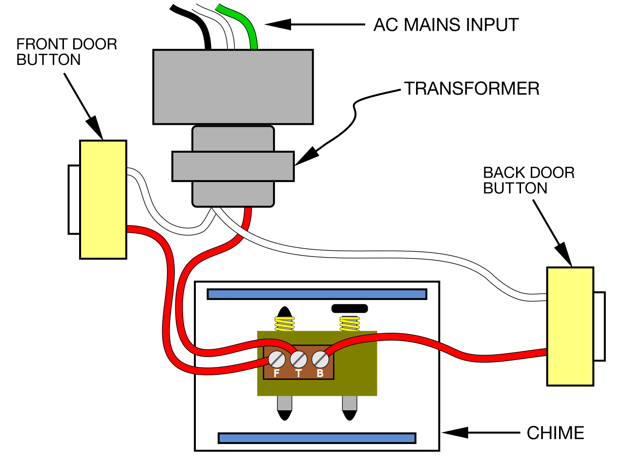
A wiring diagram for a doorbell is a detailed representation of the electrical connections between the various components of a doorbell system. These components include the transformer, push button, chime, and doorbell. Each component plays a critical role in the overall functionality of the doorbell system.
The transformer converts the incoming AC voltage to a lower AC voltage that is safe for use with the doorbell system. The push button is the switch that is pressed to activate the doorbell. The chime is the device that produces the sound when the doorbell is pressed. The doorbell is the device that is mounted on the door and produces the sound when the doorbell button is pressed.
A wiring diagram is essential for understanding how the different components of a doorbell system are connected. Without a wiring diagram, it would be difficult to troubleshoot and repair doorbell systems. Wiring diagrams are also helpful for planning new doorbell system installations.
Here are some real-life examples of how wiring diagrams are used with doorbell systems:
- An electrician may use a wiring diagram to troubleshoot a doorbell system that is not working properly.
- A homeowner may use a wiring diagram to install a new doorbell system.
- A landlord may use a wiring diagram to maintain a doorbell system in a rental property.
Understanding the relationship between the components of a doorbell system and the wiring diagram is essential for anyone who wants to install, troubleshoot, or repair doorbell systems. By understanding how the different components are connected, it is possible to ensure that the doorbell system is working properly and safely.
Connections
In the context of a wiring diagram for a doorbell, the connections between the components are critical for ensuring that the system functions properly. The diagram specifies the type of wire to be used for each connection, the length of the wire, and the polarity of the connections. The polarity of a connection refers to the positive and negative terminals of the electrical components. If the connections are not made correctly, the doorbell system may not work properly or may even be hazardous.
For example, if the positive and negative terminals of the transformer are reversed, the doorbell will not work. Similarly, if the positive and negative terminals of the chime are reversed, the chime will not produce any sound. By following the wiring diagram and making the connections correctly, you can ensure that the doorbell system is safe and functional.
Wiring diagrams are also helpful for troubleshooting doorbell systems. If the doorbell is not working properly, you can use the wiring diagram to trace the connections and identify any problems. For example, if the doorbell is not producing any sound, you can use the wiring diagram to check the connections between the chime and the doorbell. By understanding the connections between the components of a doorbell system, you can troubleshoot and repair the system quickly and easily.
In summary, the connections between the components of a doorbell system are critical for ensuring that the system functions properly. Wiring diagrams provide a detailed representation of these connections, making it easier to install, troubleshoot, and repair doorbell systems.
Voltage
In the context of a wiring diagram for a doorbell, specifying the voltage requirements is crucial for ensuring the system’s safety and functionality. The voltage requirement dictates the type of power source needed and the components that can be used in the system. Understanding the voltage aspect of a doorbell wiring diagram involves several key facets:
- Power Source: The diagram specifies the voltage required for the doorbell system, which determines the type of power source needed. It can be a battery, transformer, or direct connection to the mains supply.
- Component Compatibility: Different doorbell components, such as the transformer, chime, and doorbell button, have specific voltage ratings. The wiring diagram ensures that the components used are compatible with the voltage of the power source.
- Safety Considerations: Using the correct voltage helps prevent electrical hazards. If the voltage is too high, it can damage components or cause a fire. If the voltage is too low, the doorbell system may not function properly.
- Real-life Example: A typical doorbell system uses a transformer to convert the mains voltage (usually 120V or 240V) to a lower voltage (typically 16V or 24V) for safe operation of the doorbell.
By specifying the voltage requirements in the wiring diagram, electricians and homeowners can ensure that the doorbell system is installed and operated safely and efficiently. Understanding these voltage considerations helps prevent malfunctions, extends the lifespan of components, and ensures the doorbell system functions as intended.
Wire gauge
In the context of a wiring diagram for a doorbell, specifying the wire gauge is crucial for ensuring the system’s safe and efficient operation. The wire gauge determines the thickness and current-carrying capacity of the wire, which must be appropriate for the electrical demands of the doorbell system. Understanding this aspect of a doorbell wiring diagram involves several key facets:
- Current Draw: The diagram specifies the current draw of the doorbell system, which determines the minimum wire gauge required. Using a wire gauge that is too thin may cause the wire to overheat, posing a fire hazard.
- Wire Resistance: The wire gauge also affects the resistance of the wire. A thicker wire has lower resistance, allowing for more efficient current flow. This is especially important for longer wire runs, where voltage drop can be an issue.
- Real-life Example: A typical doorbell system uses 18-gauge wire for the low-voltage circuit between the transformer and the doorbell. This wire gauge is sufficient to handle the current draw of the doorbell.
- Code Compliance: Wiring diagrams must comply with local electrical codes, which often specify minimum wire gauge requirements for doorbell systems. Adhering to these codes ensures the safety and reliability of the installation.
By specifying the wire gauge in the wiring diagram, electricians and homeowners can ensure that the doorbell system is installed using the correct wire size, preventing potential hazards and ensuring optimal performance. Understanding these wire gauge considerations helps ensure the safety, efficiency, and longevity of the doorbell system.
Grounding
In the context of a wiring diagram for a doorbell, grounding plays a crucial role in ensuring the safe and reliable operation of the system. Grounding provides a path for electrical current to flow safely to the earth, protecting users from electrical shocks and preventing damage to equipment.
- Safety: Grounding prevents the buildup of dangerous electrical charges on the doorbell system, reducing the risk of electrical shocks to users.
- Equipment Protection: Grounding helps protect the doorbell system’s components from damage caused by electrical surges or faults.
- Compliance: Proper grounding is required by electrical codes in most regions, ensuring compliance with safety standards.
- Real-life Example: In a typical doorbell system, the ground wire is connected to the metal housing of the doorbell button and the metal chassis of the chime. This provides a path for any stray electrical current to flow to the ground, preventing electrical shocks.
Understanding the importance of grounding in a wiring diagram for a doorbell is essential for ensuring the safe and proper functioning of the system. By following the grounding instructions in the diagram, electricians and homeowners can help prevent electrical hazards and protect both users and equipment.
Troubleshooting
Wiring diagrams play a pivotal role in troubleshooting doorbell systems, enabling electricians and homeowners to diagnose and resolve issues effectively. These diagrams provide a visual representation of the electrical connections, allowing for a systematic approach to troubleshooting.
When a doorbell system malfunctions, the wiring diagram serves as a roadmap, guiding the troubleshooter through the various components and connections. By following the diagram, one can identify potential points of failure, such as loose connections, faulty wires, or malfunctioning components.
For example, if a doorbell is not producing any sound, the wiring diagram can help identify whether the problem lies in the power supply, the chime, or the doorbell button. By isolating the affected component, the troubleshooter can then focus on repairing or replacing the faulty part.
Furthermore, wiring diagrams facilitate the identification of more complex issues, such as electrical shorts or ground faults. By analyzing the connections and voltage readings, electricians can pinpoint the root cause of the problem and implement appropriate solutions.
In summary, troubleshooting wiring diagrams are essential tools for maintaining and repairing doorbell systems. They provide a structured approach to problem-solving, enabling electricians and homeowners to identify and fix issues efficiently, ensuring the reliable operation of doorbell systems.
Codes and standards
In the context of “Wiring Diagram For Doorbell,” adhering to codes and standards is paramount for ensuring the safe and proper installation of doorbell systems. These codes and standards establish guidelines for electrical wiring, materials, and practices, safeguarding against electrical hazards and ensuring the longevity of the system.
- Compliance with Regulations: Wiring diagrams must align with local electrical codes, which vary by region and municipality. These codes specify requirements for wire gauge, circuit protection, and grounding, ensuring compliance with safety regulations.
- Safety Assurance: By adhering to codes and standards, electricians can minimize the risk of electrical fires, shocks, and other hazards. Proper wiring practices prevent overheating, short circuits, and ground faults, protecting users and property.
- Insurance Coverage: Homeowners’ insurance policies may require that electrical installations, including doorbell systems, comply with local codes and standards. Failure to adhere to these standards could invalidate insurance coverage in case of an incident.
- Professionalism and Credibility: Adherence to codes and standards demonstrates professionalism and credibility among electricians. It indicates that they are knowledgeable about current regulations and committed to safe and compliant installations.
In summary, “Codes and standards: Wiring diagrams must comply with local codes and standards, ensuring that the system is installed safely and correctly” is a critical aspect of “Wiring Diagram For Doorbell.” By following these codes and standards, electricians can ensure the safety, reliability, and longevity of doorbell systems, protecting users and property.
Customization
Within the context of “Wiring Diagram For Doorbell,” the aspect of customization plays a pivotal role in tailoring doorbell systems to specific requirements and preferences. Wiring diagrams provide a flexible framework that allows for modifications and additions to meet the unique needs of each installation.
- Additional Chimes: Wiring diagrams can be customized to incorporate multiple chimes, enabling homeowners to extend the sound of the doorbell to different areas of the house. This is particularly beneficial in large homes or multi-level properties.
- Wired vs. Wireless Doorbells: Customization allows for the choice between wired and wireless doorbells. Wired doorbells offer a reliable and consistent connection, while wireless doorbells provide the convenience of portability and easy installation.
- Integration with Home Automation Systems: Wiring diagrams can be adapted to integrate doorbell systems with home automation systems, allowing for remote monitoring and control through mobile devices or voice assistants.
- Specialized Features: Customization enables the inclusion of specialized features such as motion sensors, video cameras, or intercom systems, enhancing the functionality and security of the doorbell system.
In summary, the customization aspect of “Wiring Diagram For Doorbell” empowers electricians and homeowners to tailor doorbell systems to their specific needs and preferences. By modifying and adding components, they can create doorbell systems that are not only functional but also seamlessly integrated into the overall home environment.
Documentation
In the context of “Wiring Diagram For Doorbell,” the aspect of documentation plays a critical role in ensuring the long-term functionality and ease of maintenance for doorbell systems. Wiring diagrams serve as a valuable resource for homeowners, electricians, and maintenance personnel, providing a comprehensive record of the system’s electrical connections and components.
- As-Built Reference: Wiring diagrams document the actual configuration of the doorbell system, serving as an accurate representation of the installed components and their interconnections. This is particularly useful when troubleshooting issues or making modifications to the system.
- Maintenance Guide: Wiring diagrams provide clear instructions for maintaining the doorbell system, including periodic inspections, cleaning, and component replacements. By following the diagram, maintenance personnel can efficiently identify and address potential problems.
- Troubleshooting Aid: In the event of a malfunction, wiring diagrams assist in troubleshooting the doorbell system. By analyzing the diagram, electricians can quickly identify the affected component or connection, reducing downtime and repair costs.
- Future Modifications: When expanding or modifying the doorbell system, wiring diagrams provide a roadmap for future changes. By referring to the diagram, electricians can ensure that additions or alterations are made safely and in accordance with the original design.
In summary, the documentation aspect of “Wiring Diagram For Doorbell” emphasizes the importance of having a clear and accurate record of the doorbell system’s electrical connections and components. Wiring diagrams serve as an invaluable tool for maintenance, troubleshooting, and future modifications, ensuring the long-term functionality and reliability of the doorbell system.
Safety
In the context of “Wiring Diagram For Doorbell,” safety is a paramount concern, and wiring diagrams play a crucial role in ensuring the safe installation and maintenance of doorbell systems. These diagrams provide clear instructions and guidelines that help mitigate electrical hazards, protecting both the system and its users.
A critical component of “Wiring Diagram For Doorbell,” safety measures are embedded within the design and implementation of the system. The diagram outlines proper wiring techniques, component selection, and grounding practices that adhere to established electrical codes and standards. By following these guidelines, electricians can minimize the risk of electrical fires, shocks, and other hazards.
Real-life examples of safety considerations in “Wiring Diagram For Doorbell” include:
- Specifying the correct wire gauge to handle the electrical load, preventing overheating and potential fire hazards.
- Indicating proper grounding techniques to ensure that any electrical faults are safely diverted away from the user.
- Including instructions for the installation of surge protectors to safeguard the system from voltage spikes.
Understanding the safety aspects of “Wiring Diagram For Doorbell” is essential for both professional electricians and DIY enthusiasts. By adhering to the guidelines outlined in the diagram, they can create doorbell systems that are not only functional but also safe and compliant with electrical codes.
In summary, “Safety: Wiring diagrams help ensure that doorbell systems are installed and maintained safely, reducing the risk of electrical hazards” is a cornerstone of “Wiring Diagram For Doorbell.” These diagrams provide a roadmap for safe and reliable doorbell system installations, protecting users from electrical hazards and ensuring the longevity of the system.


Related Posts


