A wiring diagram for boat gauges is a schematic representation of the electrical connections between boat gauges and other components, such as the engine, battery, and ground. It provides a visual guide to the wiring system, making it easier to troubleshoot and repair electrical problems.
Wiring diagrams are essential for maintaining the electrical system of a boat. They allow boat owners and mechanics to quickly identify and fix problems, preventing electrical fires and other hazards. Wiring diagrams also help ensure that gauges are wired correctly, providing accurate readings and optimal performance.
One of the key historical developments in wiring diagrams for boat gauges was the adoption of standardized symbols and colors. This standardization has made it easier for boat owners and mechanics to interpret and use wiring diagrams regardless of the make or model of the boat.
In the following sections, we will explore the different types of boat gauges, the components of a wiring diagram, and how to use a wiring diagram to troubleshoot and repair electrical problems.
Wiring diagrams are essential for maintaining the electrical system of a boat. They provide a visual guide to the wiring system, making it easier to troubleshoot and repair electrical problems. Wiring diagrams also help ensure that gauges are wired correctly, providing accurate readings and optimal performance.
- Components: Wiring diagrams for boat gauges include symbols representing the battery, engine, gauges, switches, and other components.
- Connections: Wiring diagrams show how the different components are connected to each other using wires.
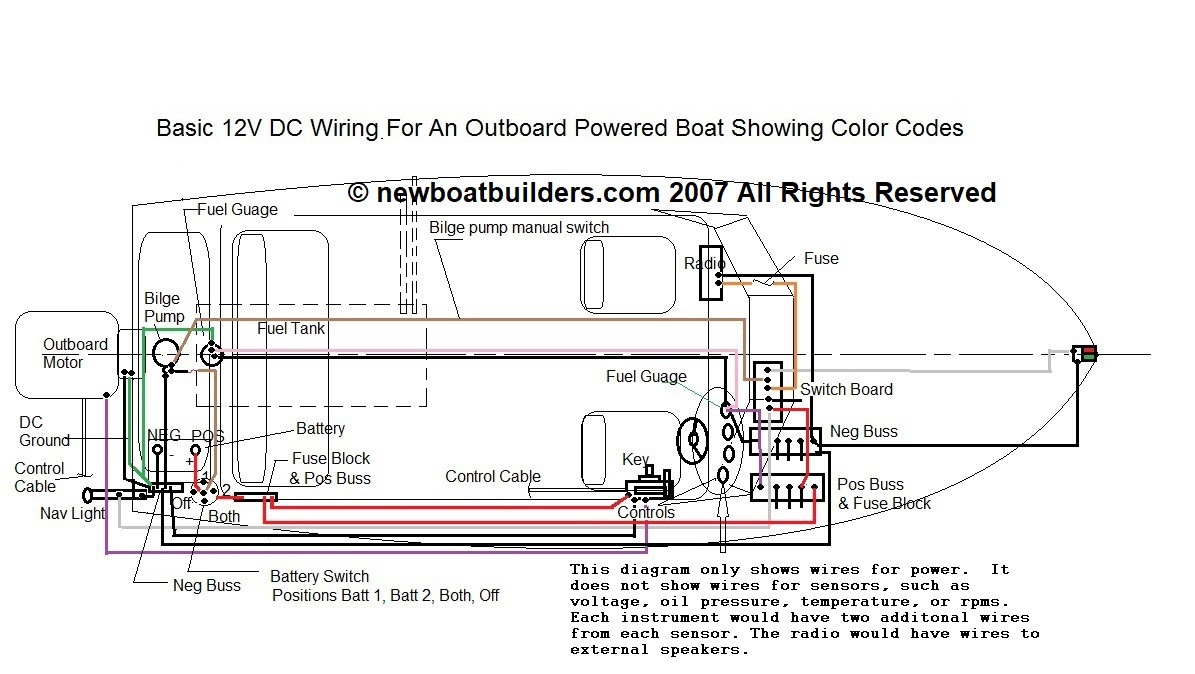
- Colors: Wiring diagrams often use color-coded wires to represent different functions, such as power, ground, and signal.
- Symbols: Wiring diagrams use standardized symbols to represent different components and connections.
- Troubleshooting: Wiring diagrams can be used to troubleshoot electrical problems by identifying the location of a fault.
- Repair: Wiring diagrams can be used to repair electrical problems by providing a guide to the wiring system.
- Safety: Wiring diagrams can help prevent electrical fires and other hazards by ensuring that the wiring system is installed correctly.
- Accuracy: Wiring diagrams help ensure that gauges are wired correctly, providing accurate readings and optimal performance.
In the following sections, we will explore these key aspects of wiring diagrams for boat gauges in more detail. We will also provide examples of how to use wiring diagrams to troubleshoot and repair electrical problems.
Components
Wiring diagrams for boat gauges use symbols to represent the various components of the electrical system, including the battery, engine, gauges, switches, and other components. These symbols provide a visual representation of the electrical system, making it easier to understand and troubleshoot. Each symbol represents a specific component, and the lines connecting the symbols represent the electrical connections between the components.
- Battery: The battery symbol represents the boat’s battery, which provides power to the electrical system.
- Engine: The engine symbol represents the boat’s engine, which generates electricity to charge the battery and power the electrical system.
- Gauges: The gauge symbols represent the various gauges on the boat, such as the speedometer, tachometer, and fuel gauge.
- Switches: The switch symbols represent the various switches on the boat, such as the light switch, bilge pump switch, and ignition switch.
These are just a few of the many components that may be included in a wiring diagram for boat gauges. By understanding the symbols used to represent these components, boat owners and mechanics can more easily interpret and use wiring diagrams to troubleshoot and repair electrical problems.
Connections
In the context of wiring diagrams for boat gauges, connections refer to the electrical pathways that allow current to flow between the various components of the electrical system. These connections are represented by lines on the wiring diagram, and they provide a visual representation of the electrical system, making it easier to understand and troubleshoot.
- Power Connections: Power connections provide a path for current to flow from the battery to the various components of the electrical system. These connections are typically represented by red wires on the wiring diagram.
- Ground Connections: Ground connections provide a path for current to flow back to the battery, completing the electrical circuit. These connections are typically represented by black wires on the wiring diagram.
- Signal Connections: Signal connections carry data between different components of the electrical system, such as between the gauges and the engine. These connections are typically represented by blue or green wires on the wiring diagram.
- Accessory Connections: Accessory connections are used to connect additional electrical devices to the boat’s electrical system, such as radios, fish finders, and bilge pumps. These connections are typically represented by yellow or white wires on the wiring diagram.
Understanding the different types of connections used in wiring diagrams for boat gauges is essential for troubleshooting and repairing electrical problems. By following the connections on the wiring diagram, boat owners and mechanics can identify the source of a problem and make the necessary repairs.
Colors
Color-coding wires in wiring diagrams is a crucial component of wiring diagrams for boat gauges. It enhances the clarity and usability of these diagrams by providing a visual cue for the different functions of the wires. By adhering to standardized color-coding conventions, electricians and boat owners can easily identify the purpose of each wire, making it easier to install, troubleshoot, and repair electrical systems.
For instance, in wiring diagrams for boat gauges, red wires typically represent power connections, black wires represent ground connections, and blue or green wires represent signal connections. This color-coding scheme helps ensure that wires are connected correctly, reducing the risk of electrical faults and ensuring the proper functioning of the boat’s electrical system.
Understanding the color-coding of wires in wiring diagrams for boat gauges is essential for anyone working with boat electrical systems. By following the color-coded wires, electricians and boat owners can quickly trace the flow of electricity throughout the system, making it easier to identify and resolve any issues that may arise.
Symbols
In the context of “Wiring Diagram For Boat Gauges”, symbols play a pivotal role in conveying the complex electrical system in a clear and concise manner. Standardized symbols provide a universal language for representing various components and connections, enabling boat owners, mechanics, and electricians to interpret and work with wiring diagrams efficiently and accurately.
- Universal Understanding: Standardized symbols transcend language barriers, allowing individuals from diverse backgrounds to comprehend wiring diagrams effortlessly. This shared understanding facilitates effective communication and collaboration among professionals working on boat electrical systems.
- Simplified Representation: Symbols simplify the representation of intricate electrical systems, making them easier to comprehend. By abstracting away unnecessary details, symbols focus on conveying the essential information, enabling users to grasp the overall structure and functionality of the system.
- Consistency and Accuracy: Standardized symbols ensure consistency in the representation of components and connections across different wiring diagrams. This consistency minimizes confusion and errors, promoting accuracy and reliability in the installation, maintenance, and repair of boat electrical systems.
- International Standards: Many standardized symbols used in wiring diagrams for boat gauges adhere to international standards, such as those established by the International Electrotechnical Commission (IEC). These standards promote global harmonization, facilitating the exchange of technical information and enhancing safety.
In conclusion, the use of standardized symbols in wiring diagrams for boat gauges is a crucial factor in ensuring effective communication, simplified representation, consistency, and adherence to international standards. These symbols empower individuals to understand, troubleshoot, and maintain boat electrical systems with greater ease and accuracy.
Troubleshooting
Wiring diagrams are essential for troubleshooting electrical problems on boat gauges. They provide a visual representation of the electrical system, making it easier to identify the location of a fault. By following the wires and connections on the wiring diagram, boat owners and mechanics can quickly pinpoint the source of a problem, such as:
- A loose connection
- A blown fuse
- A faulty component
Once the location of the fault has been identified, it can be repaired or replaced, restoring the electrical system to proper working order.
Here is an example of how a wiring diagram can be used to troubleshoot an electrical problem on a boat gauge:
The fuel gauge is not working. The boat owner checks the wiring diagram and follows the wires from the fuel gauge to the fuel tank. They find that one of the wires is loose. The boat owner tightens the wire and the fuel gauge starts working again.
Wiring diagrams are a valuable tool for troubleshooting electrical problems on boat gauges. By understanding how to use a wiring diagram, boat owners and mechanics can quickly and easily identify and repair electrical problems, keeping their boats running smoothly.
Repair
The ability of wiring diagrams to serve as repair guides for electrical problems is a crucial aspect in understanding “Wiring Diagram For Boat Gauges.” When electrical issues arise with boat gauges, such as faulty readings or complete malfunction, a wiring diagram becomes indispensable for effective troubleshooting and repair.
These diagrams provide a detailed visual representation of the electrical connections and components, allowing technicians to trace the flow of electricity and identify potential points of failure. For instance, if a fuel gauge is not functioning correctly, a mechanic can refer to the wiring diagram to locate the wires responsible for transmitting data from the fuel tank sensor to the gauge. By systematically checking the connections and continuity of these wires, they can pinpoint the exact source of the problem, whether it’s a loose connection, a damaged wire, or a faulty component.
The practical application of this understanding extends to various electrical issues on boat gauges. Wiring diagrams empower boat owners and technicians to repair problems related to faulty sensors, inoperable switches, and even complex gauge clusters. By following the step-by-step guidance provided by these diagrams, individuals can diagnose and resolve electrical problems efficiently, minimizing downtime and ensuring the smooth operation of their boat’s instrumentation.
In summary, the connection between “Repair: Wiring diagrams can be used to repair electrical problems by providing a guide to the wiring system.” and “Wiring Diagram For Boat Gauges” is highly significant. These diagrams serve as essential tools for troubleshooting, repair, and maintenance of boat gauges, enabling users to restore proper functionality, enhance safety, and ensure the reliable operation of their vessels.
Safety
Within the context of “Wiring Diagram For Boat Gauges,” the aspect of safety holds paramount importance. Wiring diagrams play a critical role in ensuring the safe and reliable operation of boat gauges by minimizing the risk of electrical fires and other hazards. This is achieved through the proper installation of the wiring system, which is guided by these diagrams.
- Prevention of Electrical Fires: Wiring diagrams help prevent electrical fires by providing a clear roadmap for the installation of electrical components and wiring. They specify the correct wire sizes, types, and connections, ensuring that the electrical system can handle the intended load without overheating or sparking.
- Elimination of Short Circuits: Short circuits, which can lead to fires, are minimized by the use of wiring diagrams. These diagrams ensure that wires are properly routed and insulated, preventing them from coming into contact with each other or with conductive surfaces.
- Grounding and Bonding: Wiring diagrams incorporate proper grounding and bonding techniques, which are essential for safety. Grounding provides a low-resistance path for electrical current to flow back to the source, preventing voltage buildup and reducing the risk of shocks. Bonding connects metal components together, equalizing their electrical potential and minimizing the risk of stray currents.
- Compliance with Standards: Wiring diagrams adhere to industry standards and regulations, which are developed to ensure the safety of electrical installations. By following these standards, boat builders and electricians can be confident that the wiring system meets the required safety criteria.
In conclusion, wiring diagrams are indispensable for ensuring the safety of boat gauges and the electrical system as a whole. By providing a comprehensive guide for the installation of electrical components and wiring, these diagrams help prevent electrical fires, eliminate short circuits, implement proper grounding and bonding, and ensure compliance with safety standards. This contributes to the safe and reliable operation of boat gauges, enhancing the overall safety of the vessel and its occupants.
Accuracy
In the context of “Wiring Diagram for Boat Gauges,” accuracy is of paramount importance for ensuring the safe and reliable operation of the boat and its systems. Wiring diagrams play a vital role in achieving accuracy by providing a detailed guide for the installation and connection of gauges. Here are some specific facets of how wiring diagrams help ensure accuracy:
- Proper Wiring: Wiring diagrams specify the correct wiring connections between gauges, sensors, and other electrical components. This ensures that gauges receive the correct electrical signals and provide accurate readings.
- Gauge Calibration: Wiring diagrams often include calibration instructions for gauges. By following these instructions, technicians can ensure that gauges are calibrated correctly, providing accurate measurements.
- Elimination of Electrical Noise: Wiring diagrams help eliminate electrical noise and interference that can affect the accuracy of gauge readings. By specifying the use of shielded cables and proper grounding techniques, wiring diagrams minimize the impact of external electrical sources.
- Testing and Troubleshooting: Wiring diagrams facilitate testing and troubleshooting of gauge accuracy. By providing a clear roadmap of the electrical system, technicians can easily identify and fix any wiring issues that may affect gauge accuracy.
Accurate gauges are essential for safe boat operation. They provide critical information to boaters about the status of the engine, fuel levels, and other important parameters. Wiring diagrams play a crucial role in ensuring the accuracy of these gauges, contributing to the overall safety and reliability of the boat.

![[DIAGRAM] Faria Boat Gauges Wiring Diagrams Diagram](https://i0.wp.com/www.cruisersforum.com/attachments/gallery/7/9/WIRINGDIAGRAMS-ELEC-D3.gif?w=665&ssl=1)


Related Posts


