A wiring diagram for a boat fuel gauge is a detailed diagram that shows how the fuel gauge is wired to the other electrical components on the boat. It provides a visual representation of the electrical connections, making it easier to troubleshoot and repair any problems that may arise.
Wiring diagrams are essential for any electrical system, as they provide a clear and concise way to see how all of the components are connected. This can be especially helpful when troubleshooting problems, as it can help you to quickly identify the source of the issue. In the case of a boat fuel gauge, the wiring diagram can help you to identify any loose connections or shorts that may be causing the gauge to malfunction.
One key historical development in the field of boat fuel gauges was the introduction of electronic fuel gauges. These gauges are much more accurate than traditional mechanical gauges, and they can also be used to track fuel consumption over time. This information can be very helpful for boaters who want to track their fuel usage and plan their trips accordingly.
In the following sections, we will take a closer look at the wiring diagram for a boat fuel gauge. We will discuss the different components of the gauge, and we will show you how to wire the gauge to the other electrical components on your boat.
Wiring diagrams are essential for any electrical system, as they provide a clear and concise way to see how all of the components are connected. This can be especially helpful when troubleshooting problems, as it can help you to quickly identify the source of the issue. In the case of a boat fuel gauge, the wiring diagram can help you to identify any loose connections or shorts that may be causing the gauge to malfunction.
- Components: The wiring diagram will show you the different components of the fuel gauge, including the gauge itself, the sending unit, and the wiring harness.
- Connections: The wiring diagram will show you how the different components of the fuel gauge are connected to each other. This includes the electrical connections, as well as the mechanical connections.
- Troubleshooting: The wiring diagram can be used to troubleshoot problems with the fuel gauge. By following the diagram, you can quickly identify any loose connections or shorts that may be causing the gauge to malfunction.
- Repair: The wiring diagram can also be used to repair problems with the fuel gauge. By following the diagram, you can easily identify the faulty component and replace it.
- Installation: The wiring diagram can be used to install a new fuel gauge. By following the diagram, you can ensure that the gauge is properly connected to the other electrical components on your boat.
- Safety: The wiring diagram can help you to ensure that the fuel gauge is installed safely. By following the diagram, you can avoid any potential electrical hazards.
- Maintenance: The wiring diagram can be used to maintain the fuel gauge. By following the diagram, you can identify any potential problems and take steps to prevent them from occurring.
- Customization: The wiring diagram can be used to customize the fuel gauge. By following the diagram, you can add additional features to the gauge, such as a low fuel warning light.
- Replacement: The wiring diagram can be used to replace the fuel gauge. By following the diagram, you can ensure that the new gauge is properly connected to the other electrical components on your boat.
These are just a few of the many aspects of a wiring diagram for a boat fuel gauge. By understanding these aspects, you can ensure that your fuel gauge is properly installed, maintained, and repaired.
Components
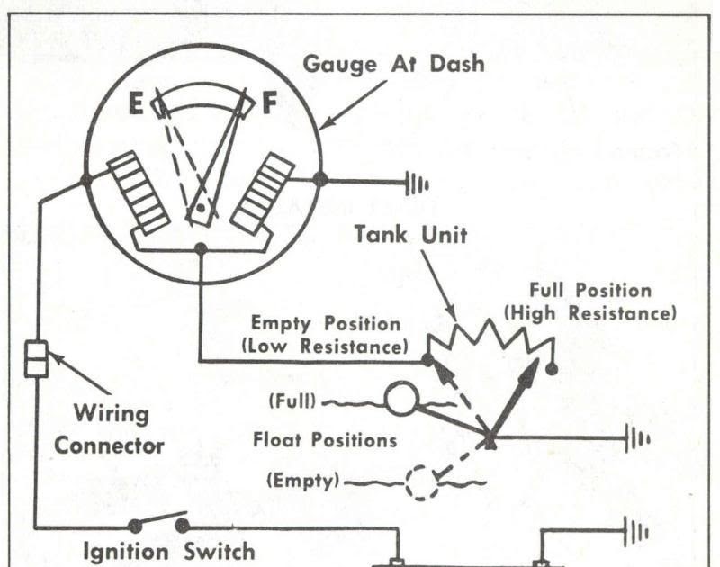
The components of a boat fuel gauge are essential to its proper function. The gauge itself is the display that shows the fuel level. The sending unit is the sensor that measures the fuel level and sends a signal to the gauge. The wiring harness is the electrical connection between the gauge and the sending unit. Without all of these components, the fuel gauge would not be able to function properly.
The wiring diagram for a boat fuel gauge shows how all of these components are connected. This diagram is essential for troubleshooting problems with the fuel gauge. By following the diagram, you can quickly identify any loose connections or shorts that may be causing the gauge to malfunction. The diagram can also be used to install a new fuel gauge or to replace a faulty one.
Here are some real-life examples of how the components of a boat fuel gauge work together:
- When you turn on the boat, the sending unit sends a signal to the gauge. The gauge then displays the fuel level.
- When the fuel level drops, the sending unit sends a different signal to the gauge. The gauge then displays the new fuel level.
- If there is a loose connection or a short in the wiring harness, the gauge may not display the correct fuel level. This could lead to you running out of fuel unexpectedly.
Understanding the components of a boat fuel gauge and how they work together is essential for keeping your boat running safely and efficiently.
Connections
In the context of a wiring diagram for a boat fuel gauge, “connections” refer to the electrical and mechanical links between the various components of the fuel gauge system. Understanding these connections is essential for troubleshooting and repairing any issues that may arise with the fuel gauge. The wiring diagram provides a visual representation of these connections, allowing you to trace the flow of electricity and identify any potential problems.
-
Electrical Connections
The electrical connections in a boat fuel gauge system are responsible for transmitting signals between the various components. These connections include the wires that connect the fuel gauge to the sending unit, as well as the wires that connect the fuel gauge to the power supply. Loose or faulty electrical connections can lead to inaccurate fuel readings or even complete failure of the fuel gauge.
-
Mechanical Connections
The mechanical connections in a boat fuel gauge system are responsible for physically securing the various components together. These connections include the screws that hold the fuel gauge in place, as well as the clamps that secure the sending unit to the fuel tank. Loose or faulty mechanical connections can lead to the fuel gauge becoming detached or misaligned, resulting in inaccurate fuel readings.
-
Ground Connections
Ground connections are essential for ensuring that the electrical system in a boat fuel gauge system is properly grounded. These connections provide a path for excess electricity to flow back to the negative terminal of the battery, preventing damage to the electrical components. Loose or faulty ground connections can lead to electrical problems, such as inaccurate fuel readings or even complete failure of the fuel gauge.
-
Power Connections
Power connections are responsible for supplying electricity to the fuel gauge. These connections include the wires that connect the fuel gauge to the power supply. Loose or faulty power connections can lead to the fuel gauge not receiving enough power to operate properly, resulting in inaccurate fuel readings or even complete failure of the fuel gauge.
By understanding the various connections in a boat fuel gauge system, you can more easily troubleshoot and repair any problems that may arise. The wiring diagram provides a valuable tool for visualizing these connections and ensuring that the fuel gauge is operating properly.
Troubleshooting
Troubleshooting is an essential aspect of any wiring diagram, including those for boat fuel gauges. By following the diagram, you can quickly identify any loose connections or shorts that may be causing the gauge to malfunction. This can save you time and money by avoiding unnecessary repairs.
-
Identifying Loose Connections
Loose connections are a common cause of problems with boat fuel gauges. These connections can occur anywhere in the wiring harness, from the gauge itself to the sending unit. Loose connections can cause the gauge to give inaccurate readings or to malfunction completely.
-
Identifying Shorts
Shorts are another common cause of problems with boat fuel gauges. A short occurs when two wires touch each other, creating a direct path for electricity to flow. This can cause the gauge to give inaccurate readings or to malfunction completely.
-
Isolating the Problem
Once you have identified the loose connection or short, you can isolate the problem by disconnecting the affected wires. This will prevent the problem from spreading to other parts of the wiring harness.
-
Repairing the Problem
Once you have isolated the problem, you can repair it by either tightening the loose connection or replacing the shorted wire. Once the repair is complete, you can reconnect the wires and test the fuel gauge to make sure that it is working properly.
By following the wiring diagram for your boat fuel gauge, you can quickly and easily troubleshoot any problems that may arise. This can save you time and money by avoiding unnecessary repairs.
Repair
A wiring diagram is an essential tool for repairing problems with a boat fuel gauge. The diagram provides a visual representation of the electrical connections in the fuel gauge system, making it easy to identify any loose connections or shorts that may be causing the gauge to malfunction. Once the faulty component has been identified, it can be replaced, and the fuel gauge will be restored to proper working order.
Here is an example of how a wiring diagram can be used to repair a boat fuel gauge:
- If the fuel gauge is not displaying the correct fuel level, the first step is to check the wiring diagram to identify the possible causes of the problem. The diagram will show the electrical connections between the fuel gauge, the sending unit, and the power supply.
- Once the possible causes have been identified, the next step is to inspect the wiring harness for any loose connections or shorts. Loose connections can be tightened, and shorted wires can be replaced.
- Once the faulty component has been repaired or replaced, the fuel gauge should be tested to ensure that it is working properly. The diagram can be used to verify that the electrical connections are correct and that the fuel gauge is receiving power.
By following the wiring diagram, boat owners can quickly and easily repair problems with their fuel gauges. This can save time and money by avoiding unnecessary repairs.
In addition to being a valuable tool for repairing fuel gauges, the wiring diagram can also be used for other purposes, such as:
- Troubleshooting problems with the fuel gauge
- Installing a new fuel gauge
- Modifying the fuel gauge system
The wiring diagram is an essential tool for anyone who owns or operates a boat. By understanding how to use the wiring diagram, boat owners can keep their fuel gauges in good working order and avoid costly repairs.
Installation
A wiring diagram is an essential tool for installing a new fuel gauge on your boat. The diagram provides a visual representation of the electrical connections in the fuel gauge system, making it easy to identify the correct wires to connect to the gauge. Without a wiring diagram, it would be very difficult to install a new fuel gauge correctly, and you could end up damaging the gauge or the electrical system on your boat.
In addition to helping you to install a new fuel gauge, a wiring diagram can also be used to troubleshoot problems with the fuel gauge system. By following the diagram, you can quickly identify any loose connections or shorts that may be causing the gauge to malfunction. A wiring diagram is also a valuable tool for modifying the fuel gauge system, such as adding a low fuel warning light.
Here is a real-life example of how a wiring diagram can be used to install a new fuel gauge:
- If the fuel gauge on your boat is not working properly, you can use a wiring diagram to help you troubleshoot the problem. The diagram will show you the electrical connections between the fuel gauge, the sending unit, and the power supply.
- Once you have identified the problem, you can use the wiring diagram to help you install a new fuel gauge. The diagram will show you the correct wires to connect to the new gauge, and it will also show you how to mount the gauge in the boat.
- Once the new fuel gauge is installed, you can use the wiring diagram to test the gauge to make sure that it is working properly.
By following the wiring diagram, you can ensure that the new fuel gauge is properly connected to the other electrical components on your boat. This will help to ensure that the gauge is working properly and that it will provide you with accurate fuel readings.
Safety
When working with any electrical system, safety should be your top priority. This is especially true when working with boat fuel gauges, as improper installation can lead to electrical fires or explosions. A wiring diagram can help you to ensure that the fuel gauge is installed safely by providing a clear and concise overview of the electrical connections.
-
Proper Grounding
One of the most important safety considerations when installing a boat fuel gauge is to ensure that it is properly grounded. This means connecting the gauge to the negative terminal of the battery. Proper grounding helps to prevent electrical shocks and fires.
-
Use of Marine-Grade Wire
When wiring a boat fuel gauge, it is important to use marine-grade wire. Marine-grade wire is designed to withstand the harsh conditions found on boats, including exposure to water, salt, and UV radiation.
-
Avoid Overloading Circuits
Overloading circuits can lead to electrical fires. When installing a boat fuel gauge, be sure to check the amperage draw of the gauge and make sure that the circuit it is connected to can handle the load.
-
Properly Insulate Connections
All electrical connections should be properly insulated to prevent shorts and electrical fires. Use heat shrink tubing or electrical tape to insulate all connections.
By following these safety tips and using a wiring diagram, you can ensure that your boat fuel gauge is installed safely and correctly. This will help to prevent electrical problems and keep your boat safe.
Maintenance
Maintaining your boat’s fuel gauge is essential for ensuring that it is working properly and providing you with accurate fuel readings. A wiring diagram can be a valuable tool for performing maintenance on your fuel gauge, as it provides a visual representation of the electrical connections in the gauge system. By following the diagram, you can identify any potential problems, such as loose connections or shorts, and take steps to prevent them from occurring.
-
Identifying Loose Connections
Loose connections are a common cause of problems with boat fuel gauges. These connections can occur anywhere in the wiring harness, from the gauge itself to the sending unit. Loose connections can cause the gauge to give inaccurate readings or to malfunction completely. By following the wiring diagram, you can identify any loose connections and tighten them, ensuring that the fuel gauge is receiving a good electrical connection.
-
Inspecting for Corrosion
Corrosion is another common problem that can affect boat fuel gauges. Corrosion can occur when water or other liquids get into the electrical connections, causing the metal to rust or corrode. Corrosion can lead to poor electrical connections, which can cause the fuel gauge to give inaccurate readings or to malfunction completely. By following the wiring diagram, you can inspect the electrical connections for any signs of corrosion and clean them if necessary.
-
Checking for Damage
Damage to the wiring harness can also cause problems with boat fuel gauges. Damage can occur if the wiring harness is cut, pinched, or otherwise damaged. Damage to the wiring harness can cause the fuel gauge to give inaccurate readings or to malfunction completely. By following the wiring diagram, you can inspect the wiring harness for any signs of damage and repair or replace the harness if necessary.
-
Testing the Fuel Gauge
Once you have inspected the wiring harness and made any necessary repairs, you should test the fuel gauge to make sure that it is working properly. To test the fuel gauge, simply turn on the ignition and check the gauge to see if it is displaying the correct fuel level. If the fuel gauge is not displaying the correct fuel level, you may need to adjust the sending unit or replace the fuel gauge.
By following these maintenance tips and using a wiring diagram, you can ensure that your boat’s fuel gauge is working properly and providing you with accurate fuel readings. This will help you to avoid running out of fuel unexpectedly and keep your boat running safely and efficiently.
Customization
The wiring diagram is a critical component of the boat fuel gauge system. It provides a visual representation of the electrical connections in the system, making it easy to identify the correct wires to connect to when adding additional features to the gauge.
For example, if you want to add a low fuel warning light to your boat fuel gauge, you can use the wiring diagram to identify the correct wires to connect the light to. The diagram will also show you how to connect the light to the gauge’s power supply.
Another example of how you can use the wiring diagram to customize your boat fuel gauge is to add a digital display to the gauge. This can be useful if you want to see the fuel level in gallons or liters, rather than just as a percentage. The wiring diagram will show you how to connect the digital display to the gauge’s sending unit.
By understanding how to use the wiring diagram, you can customize your boat fuel gauge to meet your specific needs. This can make your boat more convenient and safer to operate.
Here are some additional benefits of customizing your boat fuel gauge:
- You can add features that are not available on standard fuel gauges.
- You can customize the gauge to match the look and feel of your boat.
- You can make the gauge more accurate and reliable.
- You can save money by avoiding the cost of buying a new fuel gauge.
If you are interested in customizing your boat fuel gauge, be sure to consult with a qualified marine electrician. They can help you to choose the right features for your gauge and ensure that it is installed correctly.
Replacement
The wiring diagram for a boat fuel gauge is an essential tool for replacing the fuel gauge. The diagram provides a visual representation of the electrical connections in the fuel gauge system, making it easy to identify the correct wires to connect to when replacing the gauge. Without a wiring diagram, it would be very difficult to replace a boat fuel gauge correctly, and you could end up damaging the new gauge or the electrical system on your boat.
One of the most common reasons for replacing a boat fuel gauge is that the old gauge is no longer working properly. This could be due to a number of factors, such as a faulty sending unit, a damaged wire, or a loose connection. If you are experiencing problems with your boat fuel gauge, it is important to consult with a qualified marine electrician to diagnose the problem and determine if the gauge needs to be replaced.
Replacing a boat fuel gauge is a relatively simple process if you have the right tools and knowledge. However, it is important to follow the wiring diagram carefully to ensure that the new gauge is properly connected. If you are not comfortable working with electrical systems, it is best to hire a qualified marine electrician to replace the fuel gauge for you.


Related Posts


