A wiring diagram for AC disconnect depicts the electrical connections and components used to isolate an alternating current (AC) power source from a load or circuit. It provides a visual representation of the steps necessary to safely remove power during maintenance, repairs, or emergencies.
Wiring diagrams for AC disconnect are essential in industrial, commercial, and residential settings to ensure the safety of electricians and prevent damage to equipment. They help identify the location of disconnect switches, circuit breakers, and other protective devices, as well as the routing of wires and cables. By following a wiring diagram, electricians can quickly and accurately disconnect power without the risk of electrical shock or fire.
A notable historical development in the field of wiring diagrams for AC disconnect is the adoption of standardized symbols and conventions. This has made it easier for electricians to understand and interpret wiring diagrams, regardless of their experience or background. This standardization has contributed to improved safety and efficiency in electrical work.
In the next sections, we will delve into the components and functions of wiring diagrams for AC disconnect in more detail, exploring their applications, benefits, and considerations. We will also discuss advanced techniques and emerging technologies that are shaping the future of AC disconnect wiring diagrams.
Wiring diagrams for AC disconnect play a crucial role in electrical systems, ensuring safety, efficiency, and code compliance. Understanding the essential aspects of these diagrams is paramount for electricians, engineers, and anyone working with electrical equipment. Here are 10 key aspects to consider:
- Components: Wiring diagrams for AC disconnect depict the symbols and connections for disconnect switches, circuit breakers, fuses, and other protective devices.
- Connections: These diagrams show the flow of electricity through wires and cables, indicating the proper connections between components.
- Safety: Wiring diagrams are essential for ensuring the safe operation of electrical systems by providing a clear visual representation of the disconnect process.
- Maintenance: They facilitate troubleshooting and maintenance by providing a roadmap of the electrical system.
- Codes and Standards: Wiring diagrams must adhere to electrical codes and standards to ensure compliance and safety.
- Symbols: Standardized symbols are used to represent electrical components, making diagrams easier to understand.
- Testing: Wiring diagrams guide the testing and verification of electrical systems to ensure proper operation.
- Documentation: They serve as documentation for electrical installations, providing a permanent record of the system’s design and configuration.
- Training: Wiring diagrams are essential training tools for electricians and electrical engineers.
- Digitalization: Digital wiring diagrams using software and computer-aided design (CAD) tools are becoming increasingly common.
These aspects are interconnected and contribute to the overall effectiveness of wiring diagrams for AC disconnect. They ensure the safe and efficient operation of electrical systems, facilitate troubleshooting and maintenance, and provide a valuable reference for documentation and training. Understanding and adhering to these aspects is crucial for anyone involved in the design, installation, or maintenance of electrical systems.
Components
In the context of wiring diagrams for AC disconnect, components play a critical role in ensuring the safe and effective isolation of electrical power. These diagrams depict the symbols and connections for various types of components, including disconnect switches, circuit breakers, fuses, and other protective devices, providing a visual representation of how these components are interconnected to achieve the desired functionality.
- Disconnect Switches: Disconnect switches are manually operated devices that provide a visible break in the circuit, allowing for the isolation of power during maintenance or emergencies. Wiring diagrams clearly indicate the location and connections of disconnect switches, ensuring that they can be easily identified and operated when necessary.
- Circuit Breakers: Circuit breakers are automatic protective devices that trip when an overcurrent condition is detected, safeguarding the circuit and connected equipment from damage. Wiring diagrams show the placement and connections of circuit breakers, enabling electricians to quickly locate and reset them in the event of a tripped breaker.
- Fuses: Fuses are single-use protective devices that contain a thin wire or element that melts and breaks the circuit when an overcurrent occurs. Wiring diagrams depict the location and type of fuses used, providing guidance on their selection and replacement.
- Other Protective Devices: In addition to disconnect switches, circuit breakers, and fuses, wiring diagrams may also include other protective devices such as surge protectors, ground fault circuit interrupters (GFCIs), and arc fault circuit interrupters (AFCIs). These devices enhance the safety and reliability of the electrical system by guarding against specific electrical hazards.
Understanding the components depicted in wiring diagrams for AC disconnect is essential for proper installation, maintenance, and troubleshooting of electrical systems. These diagrams serve as a valuable guide for electricians, ensuring that all components are correctly connected and configured to provide safe and reliable power distribution.
Connections
In the context of wiring diagrams for AC disconnect, the depiction of connections is critical for understanding the flow of electricity and ensuring the proper operation of the electrical system. These diagrams clearly indicate the connections between disconnect switches, circuit breakers, fuses, and other protective devices, providing a visual representation of how electricity flows through the system. By following the connections shown in the diagram, electricians can verify that all components are correctly wired and that the system is configured to safely isolate power when necessary.
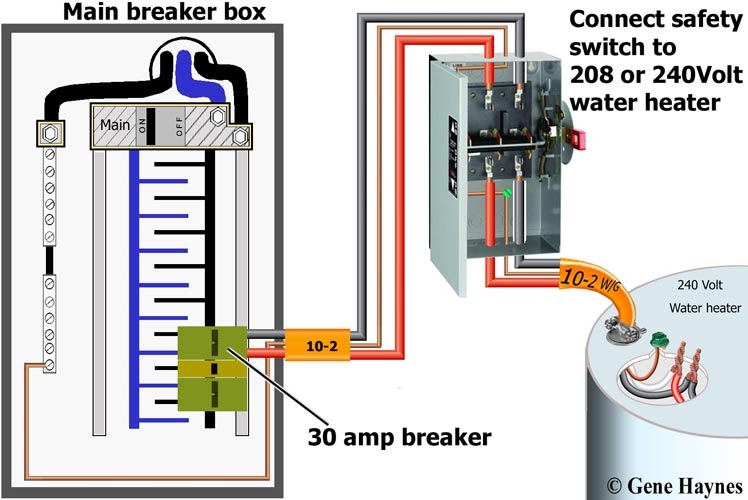
For example, in a residential electrical panel, the wiring diagram for AC disconnect will show the connections between the main breaker, branch circuit breakers, and the disconnect switch. This information is crucial for troubleshooting electrical problems, as it allows electricians to trace the flow of electricity and identify the source of any issues. Without a clear understanding of the connections, it would be difficult to determine which components are affected by a power outage or electrical fault.
The practical significance of understanding connections in wiring diagrams for AC disconnect extends to safety and reliability. Proper connections ensure that electricity flows through the intended paths, preventing short circuits, electrical fires, and damage to equipment. By adhering to the connections specified in the diagram, electricians can minimize the risk of electrical hazards and ensure the safe operation of the electrical system.
In conclusion, the proper depiction of connections in wiring diagrams for AC disconnect is essential for understanding the flow of electricity, troubleshooting electrical problems, and ensuring the safety and reliability of the electrical system. These diagrams serve as a valuable guide for electricians, providing a visual representation of the electrical connections and enabling them to make informed decisions about the operation and maintenance of the system.
Safety
Within the context of “Wiring Diagram for AC Disconnect”, the emphasis on safety is paramount. Wiring diagrams play a critical role in ensuring the safe operation of electrical systems by providing a clear visual representation of the disconnect process. These diagrams serve as essential tools for electricians to understand the electrical connections and components involved in isolating power during maintenance or emergencies.
The cause-and-effect relationship between safety and wiring diagrams for AC disconnect is evident in real-life examples. Electrical accidents can occur due to improper wiring or faulty connections. By providing a clear visual representation of the disconnect process, wiring diagrams help electricians identify potential hazards and take appropriate measures to prevent electrical shock, fires, or equipment damage.
The practical significance of understanding wiring diagrams for AC disconnect extends to various applications. In industrial settings, these diagrams are crucial for ensuring the safety of workers during maintenance and repairs. In commercial buildings, they are essential for preventing power outages and minimizing the risk of electrical fires. In residential homes, wiring diagrams for AC disconnect provide homeowners with a clear understanding of how to safely isolate power in case of an emergency.
In conclusion, wiring diagrams for AC disconnect are indispensable for ensuring the safe operation of electrical systems. By providing a clear visual representation of the disconnect process, these diagrams empower electricians and homeowners alike to make informed decisions about electrical maintenance and troubleshooting. Understanding the connection between safety and wiring diagrams is critical for preventing electrical accidents and promoting the safe and efficient use of electricity.
Maintenance
Within the context of “Wiring Diagram for AC Disconnect”, the role of maintenance is closely intertwined with the effectiveness of the diagram. Wiring diagrams serve as invaluable tools that facilitate troubleshooting and maintenance procedures by providing a clear visual representation of the electrical system. This roadmap-like quality enables electricians to efficiently identify and address electrical issues, ensuring the smooth operation and longevity of the system.
The cause-and-effect relationship between maintenance and wiring diagrams for AC disconnect is evident in real-life scenarios. Consider an industrial setting where a complex electrical system requires regular maintenance. Without a comprehensive wiring diagram, troubleshooting electrical faults can be a time-consuming and challenging task. However, with a well-documented wiring diagram, electricians can quickly trace the electrical connections, identify the faulty component, and perform the necessary repairs or replacements.
The practical significance of understanding the connection between maintenance and wiring diagrams for AC disconnect extends to various applications. In commercial buildings, these diagrams guide maintenance personnel in performing preventive maintenance tasks, reducing the risk of electrical failures and ensuring uninterrupted operations. In residential homes, wiring diagrams empower homeowners with the knowledge to safely troubleshoot minor electrical issues and perform basic maintenance tasks, promoting electrical safety and minimizing the need for costly repairs.
In summary, the maintenance aspect of wiring diagrams for AC disconnect plays a critical role in ensuring the efficient troubleshooting and maintenance of electrical systems. These diagrams provide a visual roadmap that guides electricians and maintenance personnel in identifying and resolving electrical issues, promoting safety, reliability, and cost-effectiveness. Understanding this connection is essential for maintaining the integrity and functionality of electrical systems in various settings.
Codes and Standards
In the context of “Wiring Diagram for AC Disconnect”, adherence to electrical codes and standards is a crucial aspect that underscores the safety and compliance of electrical installations. These codes and standards provide a set of guidelines and regulations that govern the design, installation, and maintenance of electrical systems, including the proper use of wiring diagrams for AC disconnect.
- Compliance with Regulatory Bodies: Wiring diagrams for AC disconnect must comply with the requirements of regulatory bodies such as the National Electrical Code (NEC) and local building codes. These codes ensure that electrical installations meet minimum safety standards, reducing the risk of electrical fires, shocks, and other hazards.
- Safety for Electrical Workers: By adhering to electrical codes and standards, wiring diagrams provide clear instructions for electricians to safely isolate and disconnect power during maintenance, repairs, or emergencies. This reduces the likelihood of accidents and ensures the well-being of those working on electrical systems.
- Protection of Equipment and Property: Properly designed and installed wiring diagrams for AC disconnect help protect electrical equipment and property from damage. By ensuring that disconnect devices are correctly sized and connected, these diagrams minimize the risk of overloads and short circuits that could lead to equipment failure or fires.
- Insurance and Liability: Adherence to electrical codes and standards is often a requirement for insurance coverage. Insurance companies may deny claims or limit coverage for electrical accidents or property damage if wiring diagrams do not meet the required standards.
In summary, wiring diagrams for AC disconnect must adhere to electrical codes and standards to ensure compliance, safety, and the protection of electrical workers, equipment, and property. Understanding and adhering to these codes and standards is essential for the design, installation, and maintenance of safe and reliable electrical systems.
Symbols
Within the context of “Wiring Diagram for AC Disconnect”, the use of standardized symbols plays a pivotal role in the clarity and comprehension of these diagrams. Standardized symbols serve as a universal language, providing a common set of graphical representations for electrical components. This shared visual language facilitates effective communication between electricians, engineers, and other professionals working on electrical systems.
- Simplified Representation: Standardized symbols simplify complex electrical systems by representing each component with a unique and easily recognizable symbol. This simplification enables electricians to quickly identify and understand the function of each component, even if they are unfamiliar with the specific make or model.
- Consistency across Diagrams: The use of standardized symbols ensures consistency across different wiring diagrams for AC disconnect. Regardless of the project or industry, electricians can rely on the same symbols to represent similar components. This consistency streamlines the process of interpreting and working with wiring diagrams.
- Reduced Errors: Standardized symbols minimize the risk of errors in wiring diagrams. By using a common set of symbols, the chances of misinterpreting or confusing components are significantly reduced. This enhances the accuracy and reliability of electrical system design and installation.
- Global Understanding: Electrical symbols are universally recognized, transcending language and cultural barriers. This enables effective collaboration and exchange of information between professionals from different countries and backgrounds.
In summary, standardized symbols in wiring diagrams for AC disconnect enhance understanding, promote consistency, reduce errors, and facilitate global collaboration. The adoption of standardized symbols is a cornerstone of electrical engineering and contributes to the safety, efficiency, and reliability of electrical systems worldwide.
Testing
Within the context of “Wiring Diagram for AC Disconnect”, testing plays a critical role in ensuring the proper operation and safety of electrical systems. Wiring diagrams serve as essential guides during the testing and verification process, providing a visual representation of the electrical connections and components. By following the steps outlined in the wiring diagram, electricians can systematically test each component and connection to identify any potential issues or malfunctions.
The cause-and-effect relationship between testing and wiring diagrams for AC disconnect is evident in real-life scenarios. Consider an industrial setting where a newly installed electrical system requires thorough testing before being put into operation. Without a comprehensive wiring diagram, testing would be a haphazard and time-consuming task. However, with a well-documented wiring diagram, electricians can methodically test each component, starting from the power source and working their way through the circuit, ensuring that all connections and devices are functioning correctly.
The practical significance of understanding the connection between testing and wiring diagrams for AC disconnect extends to various applications. In commercial buildings, these diagrams guide electricians in performing periodic maintenance and safety checks, ensuring that the electrical system remains in optimal condition. In residential homes, wiring diagrams empower homeowners to conduct basic electrical testing, such as checking for proper grounding and polarity, promoting electrical safety and preventing potential hazards.
In summary, testing is an essential component of wiring diagrams for AC disconnect, providing a systematic approach to verifying the proper operation of electrical systems. By understanding and adhering to the testing procedures outlined in the diagram, electricians and homeowners can ensure the safety, reliability, and efficiency of their electrical systems.
Documentation
Documentation is a fundamental aspect of “Wiring Diagram for AC Disconnect” as it provides a permanent and detailed record of the electrical system’s design and configuration. This documentation is critical for various reasons:
- Historical Reference: Wiring diagrams serve as historical references, documenting the evolution and modifications made to the electrical system over time. This information is invaluable for troubleshooting, maintenance, and future upgrades.
- Maintenance and Repairs: Accurate documentation simplifies maintenance and repair tasks by providing a visual guide to the system’s components and connections. Electricians can quickly identify and locate specific components, reducing downtime and ensuring efficient repairs.
- Safety Compliance: Well-documented wiring diagrams demonstrate compliance with electrical codes and standards, which are essential for safety and insurance purposes. They provide a clear record of the system’s design and installation, ensuring adherence to regulatory requirements.
- Collaboration and Communication: Wiring diagrams facilitate effective collaboration and communication among electricians, engineers, and other professionals involved in the project. They provide a common reference point for discussions, decision-making, and troubleshooting.
Real-life examples of documentation within “Wiring Diagram for AC Disconnect” include:
- Electrical contractors use wiring diagrams to document the design and installation of AC disconnect systems in residential, commercial, and industrial buildings.
- Maintenance personnel rely on wiring diagrams to troubleshoot and repair AC disconnect systems, ensuring the safety and reliability of electrical equipment.
- Inspectors use wiring diagrams to verify compliance with electrical codes and standards during inspections and audits.
Understanding the connection between documentation and “Wiring Diagram for AC Disconnect” is crucial for ensuring the safety, efficiency, and longevity of electrical systems. Proper documentation enables effective maintenance, troubleshooting, and compliance with regulatory requirements.
Training
Within the context of “Wiring Diagram for AC Disconnect”, training plays a pivotal role in the development of skilled and competent electrical professionals. Wiring diagrams serve as essential training tools, providing a visual representation of electrical systems and the safe practices associated with AC disconnect operations. By studying and analyzing these diagrams, electricians and electrical engineers gain a thorough understanding of electrical circuits, component interconnections, and the proper procedures for isolating power.
The cause-and-effect relationship between training and wiring diagrams for AC disconnect is evident in real-life scenarios. Consider an electrical training program where students are tasked with installing and maintaining an electrical system. Without a clear understanding of wiring diagrams, these students would face significant challenges in comprehending the system’s design and functionality. However, with the guidance of wiring diagrams, they can trace the flow of electricity, identify individual components, and learn the proper techniques for isolating power during maintenance or emergencies.
The practical significance of understanding the connection between training and wiring diagrams for AC disconnect extends to various applications. In industrial settings, electricians rely on wiring diagrams to safely perform maintenance and troubleshooting tasks on complex electrical equipment. In commercial buildings, electrical engineers use wiring diagrams to design and install electrical systems that meet specific safety and efficiency requirements. In residential homes, homeowners can benefit from a basic understanding of wiring diagrams to perform minor electrical repairs and ensure the safe operation of their electrical systems.
In summary, training is a critical component of wiring diagrams for AC disconnect, providing the foundation for electrical professionals to develop the skills and knowledge necessary for the safe and effective operation of electrical systems. Wiring diagrams serve as essential training tools, enabling electricians and electrical engineers to visualize electrical circuits, understand component interconnections, and learn the proper procedures for isolating power. This training is essential for ensuring the safety and reliability of electrical systems in various settings, from industrial facilities to residential homes.
Digitalization
Within the context of “Wiring Diagram for AC Disconnect”, digitalization is revolutionizing the way electrical systems are designed, documented, and maintained. Digital wiring diagrams, created using specialized software and computer-aided design (CAD) tools, offer numerous advantages over traditional paper-based diagrams, making them increasingly prevalent in the electrical industry.
- Enhanced Accuracy and Precision: Digital wiring diagrams eliminate the errors and inconsistencies that can arise from manual drafting. CAD software ensures precise alignment, consistent symbols, and accurate connections, resulting in highly reliable and error-free diagrams.
- Improved Collaboration and Communication: Digital diagrams facilitate seamless collaboration among project stakeholders, including electricians, engineers, and architects. CAD files can be easily shared, reviewed, and modified, enabling real-time updates and effective communication throughout the project lifecycle.
- Automated Generation and Updates: Digital wiring diagrams can be generated automatically from electrical design software, reducing the time and effort required for manual drafting. Additionally, updates to the electrical system can be quickly reflected in the digital diagram, ensuring that it remains current and accurate.
- Integration with Building Information Modeling (BIM): Digital wiring diagrams can be integrated with BIM models, providing a comprehensive view of the entire building’s electrical system. This integration enhances coordination between different design disciplines, reduces errors, and improves overall project efficiency.
The adoption of digital wiring diagrams for AC disconnect is gaining traction in various settings, including industrial facilities, commercial buildings, and residential homes. As the electrical industry continues to embrace digitalization, the benefits of digital wiring diagrams will become increasingly apparent, leading to safer, more efficient, and more reliable electrical systems.


![[DIAGRAM] Electrical Disconnect Diagram](https://i0.wp.com/us.v-cdn.net/6024911/uploads/attachments/9241/3077.jpg?w=665&ssl=1)


![[Download 27+] Wiring Diagram For Ac Disconnect](https://lh3.googleusercontent.com/proxy/HqBAMM4-wbI4gWbE9D5_pGSiWZnXEwpUvPGT3YpZAOCiDzVfVilIFGNbsemmOIROurPHgDJ_FFmHs8N_X9T0KwhbV9MhvpgFWxqwUzZem-vNk8v3C_SAPQ=w1200-h630-p-k-no-nu)

Related Posts


