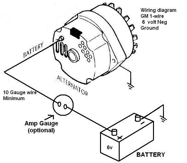
A Wiring Diagram for a One Wire Alternator provides a visual representation of the electrical connections necessary to install and operate a one-wire alternator. One wire alternators are commonly used in automotive applications, and the wiring diagram shows how to connect the alternator to the vehicle’s battery, ignition switch, and other electrical components.
A one-wire alternator is an alternator that uses a single wire to connect to the vehicle’s electrical system. This design simplifies the wiring process and makes it easier to install the alternator. The benefits of using a one-wire alternator include ease of installation and reduced wiring complexity, making it a popular choice for automotive applications.
A key historical development in the evolution of one-wire alternators was the introduction of voltage regulators. Voltage regulators control the output voltage of the alternator, ensuring that it provides a consistent voltage to the vehicle’s electrical system. The use of voltage regulators has improved the reliability and performance of one-wire alternators.
The following article will provide a more detailed explanation of the wiring diagram for a one-wire alternator, including specific instructions on how to install and connect the alternator. It will also discuss troubleshooting tips and the importance of maintaining the alternator to ensure optimal performance.
Wiring diagrams provide valuable instructions for understanding and working with electrical systems. To comprehend wiring diagrams for one-wire alternators, it is crucial to grasp their essential aspects.
- Connections: Depicts the flow of electricity between components.
- Components: Identifies each component in the circuit and its function.
- Power Source: Indicates the source of electrical power for the circuit.
- Ground: Shows the path for completing the electrical circuit.
- Wire Gauge: Specifies the thickness of the wires used, affecting current capacity.
- Fuses: Protects the circuit from overcurrent conditions.
- Relays: Controls the flow of electricity using electromagnetism.
- Troubleshooting: Guides in identifying and resolving electrical issues.
These aspects are interconnected. Connections show how components are linked, while components determine the function of the circuit. The power source provides energy, and the ground completes the circuit, allowing current to flow. Wire gauge and fuses ensure safe operation, while relays enhance control. Understanding these aspects empowers individuals to interpret wiring diagrams accurately and troubleshoot electrical systems effectively.
Connections
In the context of a wiring diagram for a one-wire alternator, connections play a crucial role in understanding the flow of electricity between components. These diagrams provide a visual representation of the electrical connections necessary to install and operate a one-wire alternator, making it easier to comprehend the electrical system of a vehicle.
Connections in a wiring diagram for a one-wire alternator depict the path of electrical current as it flows from the alternator to the battery, ignition switch, and other electrical components. By following the connections, one can trace the flow of electricity and identify the function of each component within the system. Understanding these connections is essential for troubleshooting electrical problems and ensuring the proper operation of the alternator and the vehicle’s electrical system.
For example, in a typical wiring diagram for a one-wire alternator, the main connection is between the alternator and the battery. This connection allows the alternator to charge the battery, providing power to the vehicle’s electrical system. Other connections include the ignition switch, which provides power to the alternator when the vehicle is running, and various electrical loads, such as lights, audio systems, and power windows, which draw power from the alternator.
Understanding the connections in a wiring diagram for a one-wire alternator is crucial for several reasons. First, it allows individuals to troubleshoot electrical problems more effectively. By tracing the connections, one can identify loose or damaged wires, faulty components, or other issues that may be causing electrical problems. Second, it enables individuals to make modifications to the electrical system safely and correctly. By understanding the flow of electricity, one can add or remove components without creating electrical hazards.
Components
In the context of a wiring diagram for a one-wire alternator, components play a crucial role in understanding the function and operation of the electrical system. The wiring diagram identifies each component in the circuit and its function, providing a clear visual representation of how the alternator and its associated components work together to generate and distribute electrical power.
Components within a wiring diagram for a one-wire alternator include the alternator itself, the battery, the ignition switch, voltage regulator, and various electrical loads, such as lights, audio systems, and power windows. Each component has a specific function within the system. The alternator generates electrical power, the battery stores electrical energy, the ignition switch controls the flow of power to the alternator, the voltage regulator maintains a consistent voltage output from the alternator, and the electrical loads draw power from the system.
Understanding the function of each component is critical for troubleshooting electrical problems and ensuring the proper operation of the alternator and the vehicle’s electrical system. By identifying the function of each component, individuals can trace the flow of electricity through the circuit and identify potential issues. For example, if a headlight is not working, one can use the wiring diagram to identify the components responsible for powering the headlight and check for any loose connections, faulty components, or other problems.
Furthermore, understanding the function of each component allows individuals to make modifications to the electrical system safely and correctly. By knowing the role of each component, one can add or remove components without creating electrical hazards. For example, one may want to add an aftermarket audio system to their vehicle. By referring to the wiring diagram, one can identify the appropriate power source and connections for the new audio system, ensuring that it is properly integrated into the existing electrical system.
Power Source
In the context of a wiring diagram for a one-wire alternator, the “Power Source” aspect plays a fundamental role in understanding the overall electrical system and its functionality. It identifies the component or external source that provides the electrical power to operate the alternator and other components within the circuit.
- Battery: The most common power source for a one-wire alternator is the vehicle’s battery. It provides the initial power to energize the alternator and serves as a reservoir for storing electrical energy.
- External Power Supply: In some applications, an external power supply, such as a battery charger or a power converter, can be used to provide power to the alternator. This is typically done during testing or maintenance procedures.
- Auxiliary Power Source: Some vehicles may have an auxiliary power source, such as a secondary battery or a capacitor, that supports the electrical system and provides additional power when needed.
- Regulator: The voltage regulator plays a crucial role in controlling the power output of the alternator. It ensures that the alternator maintains a stable voltage level, preventing overcharging or undercharging of the battery.
Understanding the power source aspect of a wiring diagram for a one-wire alternator is essential for troubleshooting electrical problems and ensuring the proper operation of the charging system. By knowing the source of electrical power, technicians and enthusiasts can effectively diagnose and resolve issues related to power supply, voltage regulation, and alternator performance.
Ground
In the context of a wiring diagram for a one-wire alternator, the “Ground” aspect plays a critical role in understanding how the electrical circuit is completed, allowing current to flow and the alternator to function properly.
A “ground” in an electrical circuit refers to a connection to a reference point with zero electrical potential. In the case of a one-wire alternator, the ground connection provides a path for the electrical current to complete its circuit back to the negative terminal of the battery. Without a proper ground connection, the alternator would not be able to generate and deliver electrical power effectively.
In a wiring diagram for a one-wire alternator, the ground connection is typically represented by a symbol that resembles an inverted “T” shape. This symbol indicates the point in the circuit where the ground connection is made. The ground wire, which is usually black or brown, connects this point to the negative terminal of the battery, completing the circuit.
Understanding the importance of the ground connection in a wiring diagram for a one-wire alternator is crucial for troubleshooting electrical problems and ensuring the proper operation of the charging system. A faulty ground connection can lead to various issues, such as reduced alternator output, flickering lights, or even complete electrical failure. By recognizing the role of the ground connection and its representation in a wiring diagram, technicians and enthusiasts can effectively diagnose and resolve these problems.
Wire Gauge
In the context of a wiring diagram for a one-wire alternator, the wire gauge plays a critical role in ensuring the proper functioning and safety of the electrical system. Wire gauge refers to the thickness of the electrical wires used in the circuit, which directly affects the amount of current the wires can safely carry. Thicker wires with a lower gauge number can carry more current than thinner wires with a higher gauge number.
In a one-wire alternator wiring diagram, the wire gauge is carefully selected to meet the specific current requirements of the alternator and the electrical components it powers. Using wires with an insufficient gauge can lead to excessive voltage drop, overheating, and potential electrical hazards. Conversely, using wires with a larger gauge than necessary can increase the cost and complexity of the wiring harness without providing significant benefits.
To determine the appropriate wire gauge for a one-wire alternator wiring diagram, it is necessary to consider factors such as the alternator’s output current, the length of the wire runs, and the ambient temperature. Automotive industry standards and manufacturers’ recommendations provide guidelines for selecting the appropriate wire gauge based on these factors.
Understanding the significance of wire gauge in a one-wire alternator wiring diagram is essential for designing, installing, and maintaining electrical systems in vehicles. Proper wire selection ensures that the alternator can deliver the required power efficiently and safely, preventing electrical problems and potential hazards.
Fuses
Within the context of a wiring diagram for a one-wire alternator, fuses play a critical role in safeguarding the electrical system from potential damage caused by overcurrent conditions. Overcurrent can occur due to various factors, such as short circuits, overloads, or faulty components, and can lead to excessive heat, damage to electrical components, or even fire. Fuses are designed to interrupt the flow of current when it exceeds a predetermined threshold, effectively protecting the circuit and preventing catastrophic failures.
- Fuse Type: Fuses come in various types, including blade fuses, cartridge fuses, and glass fuses, each with its own specific characteristics and applications. In a one-wire alternator wiring diagram, blade fuses are commonly used due to their compact size and ease of replacement.
- Fuse Rating: The fuse rating, typically measured in amperes (A), indicates the maximum amount of current the fuse can safely handle before it blows. The appropriate fuse rating for a one-wire alternator wiring diagram is determined based on the alternator’s output current and the current draw of the connected electrical components.
- Fuse Placement: Fuses are strategically placed in the wiring harness, typically near the power source or at critical points in the circuit. This placement ensures that the fuse is in a position to interrupt the current flow effectively in the event of an overcurrent condition.
- Fuse Protection: When a fuse blows due to overcurrent, it sacrifices itself to protect the rest of the circuit. The blown fuse needs to be replaced with a new fuse of the same rating to restore the circuit’s functionality.
Understanding the role of fuses in a wiring diagram for a one-wire alternator is crucial for ensuring the safe and reliable operation of the electrical system in various applications. By preventing overcurrent conditions, fuses help protect expensive components, prevent electrical fires, and maintain the overall integrity of the wiring harness.
Relays
In a wiring diagram for a one-wire alternator, relays play a critical role in controlling the flow of electricity and managing various electrical functions within the system. A relay is an electromagnetic switch that uses a small amount of electrical current to control a larger amount of current. This allows for the efficient and safe operation of electrical components, such as the alternator, starter motor, and other accessories.
Within the context of a one-wire alternator wiring diagram, relays are typically used to control the following functions:
- Alternator Engagement: Relays can be used to engage or disengage the alternator from the electrical system, allowing for controlled charging of the battery.
- Voltage Regulation: Relays can be integrated with voltage regulators to maintain a stable voltage output from the alternator, preventing overcharging or undercharging of the battery.
- Accessory Control: Relays can be used to control the operation of various electrical accessories, such as headlights, wipers, and power windows, providing centralized control and protection.
Understanding the role of relays in a wiring diagram for a one-wire alternator is essential for troubleshooting electrical problems and ensuring the proper functioning of the charging system. By comprehending the operation and purpose of relays, individuals can effectively diagnose and resolve issues related to alternator performance, voltage regulation, and accessory control.
Troubleshooting
Within the context of “Wiring Diagram for a One-Wire Alternator,” troubleshooting plays a pivotal role in maintaining the electrical system’s optimal performance. It provides a systematic approach to identifying and resolving electrical issues, ensuring the alternator and associated components function correctly. By understanding the principles of troubleshooting and effectively utilizing wiring diagrams, individuals can diagnose and rectify electrical problems, preventing system failures and ensuring reliable operation.
- Symptom Analysis: Interpreting observable symptoms, such as flickering lights, slow cranking, or charging system malfunctions, provides valuable clues in pinpointing the root cause of electrical issues.
- Circuit Testing: Using a multimeter or other diagnostic tools to measure voltage, current, and resistance allows technicians to verify circuit integrity, identify faulty components, and trace the flow of electricity.
- Component Inspection: Examining alternator components, such as the voltage regulator, diodes, and brushes, for signs of wear, corrosion, or damage can help identify potential sources of electrical problems.
- Wiring Verification: Ensuring proper connections, secure terminals, and the absence of shorts and open circuits in the wiring harness is crucial for maintaining a reliable electrical system.
By understanding these key facets of troubleshooting in relation to “Wiring Diagram for a One-Wire Alternator,” individuals can effectively diagnose and resolve electrical issues, ensuring the proper functioning of the charging system and the overall electrical integrity of the vehicle.


![[DIAGRAM] Wiring Diagram For 1 Wire Gm Alternator](https://i0.wp.com/capestarter.com/ESW/Files/2wire12volt.jpg?w=665&ssl=1)


Related Posts


