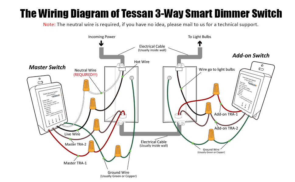
Wiring Diagram for a 3-Way Dimmer Switch is a schematic representation of the electrical connections used to install a 3-way dimmer switch, which allows control of a single light fixture from two separate locations. An example is a bedroom where there are light switches by the door and by the bed.
Wiring diagrams are crucial for ensuring proper operation and safety. They guide electricians in connecting the switch, dimmer, light fixture, and power source correctly. Benefits include improved lighting control, energy savings, and enhanced aesthetics. A key historical development is the introduction of electronic dimmers in the 1960s, which replaced mechanical dimmers and offered greater dimming range and efficiency.
This article will delve deeper into the components, wiring techniques, and troubleshooting tips for 3-way dimmer switch installations.
Wiring diagrams for 3-way dimmer switches are crucial for ensuring the proper installation and operation of these electrical devices. Understanding the key aspects of wiring diagrams is essential for electricians, homeowners, and anyone involved in electrical work.
- Components: Switches, dimmers, light fixtures, wires
- Connections: How the components are wired together
- Power Source: Where the electrical power comes from
- Safety: Ensuring the installation meets electrical codes and standards
- Control: How the switch and dimmer operate the light fixture
- Troubleshooting: Identifying and resolving common issues
- Symbols: Understanding the electrical symbols used in the diagram
- Variations: Different types of wiring diagrams for different switch configurations
- Tools: Required tools for installation and troubleshooting
These key aspects provide a comprehensive understanding of wiring diagrams for 3-way dimmer switches. They encompass the electrical components, connections, safety considerations, control mechanisms, troubleshooting techniques, and essential tools. By understanding these aspects, individuals can ensure accurate installations, resolve electrical issues, and maintain the proper functioning of their lighting systems.
Components
In the context of wiring diagrams for 3-way dimmer switches, components play a fundamental role in ensuring the proper functionality and control of lighting systems. These components include switches, dimmers, light fixtures, and wires, each serving a specific purpose and requiring careful consideration during installation.
- Switches: 3-way switches are specialized electrical switches that allow for the control of a single light fixture from two separate locations. They come in various styles, such as toggle switches or rocker switches, and are designed to handle the specific electrical requirements of dimmer circuits.
- Dimmers: Dimmers are essential components that enable the adjustment of light intensity. They come in different types, including rotary dimmers, slide dimmers, or electronic dimmers, and are rated for specific wattage and voltage levels to ensure compatibility with the light fixtures.
- Light Fixtures: Light fixtures are the devices that house the light source and distribute the light. They can be categorized into various types, such as recessed lighting, chandeliers, or pendant lights, and must be compatible with the dimmer switch and wiring system.
- Wires: Electrical wires are the conductors that carry electrical current throughout the circuit. They come in different gauges and materials, and must be properly sized and insulated to handle the electrical load and voltage requirements of the dimmer switch and light fixture.
Understanding the components of wiring diagrams for 3-way dimmer switches is crucial for proper installation and maintenance. Each component plays a vital role in the functionality and safety of the electrical system, and careful consideration must be given to their selection, compatibility, and proper connection.
Connections
In the realm of wiring diagrams for 3-way dimmer switches, connections hold paramount importance. They represent the intricate network of electrical pathways that link the various components, enabling the seamless control and adjustment of lighting systems. Without proper connections, the dimmer switch would be rendered inoperable, and the desired functionality of controlling lights from multiple locations would be unattainable.
The connections within a wiring diagram for a 3-way dimmer switch dictate the flow of electrical current, allowing for the adjustment of light intensity and the switching of lights on and off from different locations. Each component the switches, dimmer, light fixture, and wires must be meticulously connected according to the specified wiring scheme to ensure proper operation.
Real-life examples of connections in a wiring diagram for a 3-way dimmer switch include the connections between the switch terminals and the wires, the connections between the dimmer terminals and the wires, the connections between the light fixture terminals and the wires, and the connections between the wires and the power source. These connections must be secure, properly insulated, and adhere to electrical codes to prevent electrical hazards and ensure reliable performance.
Understanding the connections within a wiring diagram for a 3-way dimmer switch is crucial for electricians, homeowners, and anyone involved in electrical work. This understanding enables the proper installation, troubleshooting, and maintenance of lighting systems, ensuring safety, efficiency, and the desired level of lighting control.
Power Source
In the context of a wiring diagram for a 3-way dimmer switch, the power source holds paramount importance, as it provides the electrical energy necessary for the operation of the dimmer switch and the connected light fixture. Understanding the power source and its related components is essential for ensuring the proper installation, functionality, and safety of the lighting system.
- Electrical Panel: The electrical panel, also known as the breaker box, is the central distribution point for electricity in a building. It houses circuit breakers or fuses that protect electrical circuits from overcurrent conditions. The power source for a 3-way dimmer switch is typically derived from a circuit breaker in the electrical panel.
- Electrical Wiring: Electrical wiring, consisting of insulated conductors, carries electrical current from the power source to the dimmer switch and light fixture. The wiring must be properly sized and installed to handle the electrical load and voltage requirements of the lighting system.
- Voltage: Voltage is the electrical potential difference between two points in a circuit. The voltage supplied to the dimmer switch must match the voltage rating of the dimmer and the light fixture to ensure proper operation.
- Grounding: Grounding provides a safe path for electrical current to flow in the event of a fault. Proper grounding is essential for the safe operation of the dimmer switch and light fixture, and it helps protect against electrical shock hazards.
Comprehending the power source and its components in the context of a wiring diagram for a 3-way dimmer switch is crucial for ensuring a safe and functional lighting system. Proper installation, maintenance, and troubleshooting of the electrical system require a thorough understanding of the power source and its related components.
Safety
When working with electrical systems, adhering to established electrical codes and standards is paramount for ensuring the safety of both individuals and property. The wiring diagram for a 3-way dimmer switch serves as a vital guide in this regard, providing a clear roadmap for proper installation practices that comply with these regulations.
Electrical codes and standards are developed by experts to minimize the risk of electrical fires, shocks, and other hazards. By following these guidelines, electricians can ensure that the dimmer switch is installed correctly, with appropriate wire sizing, proper grounding, and secure connections. These measures help prevent electrical faults, overloads, and potential accidents.
Real-life examples of safety considerations in the wiring diagram for a 3-way dimmer switch include specifying the use of specific wire gauges that can handle the electrical load of the dimmer and light fixture, indicating the proper connection of the grounding wire to provide a safe path for excess current, and outlining the correct placement of electrical boxes and switches to maintain proper clearances and prevent accidental contact with live wires.
Understanding the connection between safety and the wiring diagram for a 3-way dimmer switch is crucial for ensuring a safe and reliable lighting system. By adhering to established electrical codes and standards, homeowners and electricians can minimize electrical hazards, protect property, and maintain a safe living environment.
Control
In the context of a wiring diagram for a 3-way dimmer switch, the control aspect plays a central role in understanding how the switch and dimmer interact to operate the light fixture. The wiring diagram provides a visual representation of the electrical connections that enable the control of light intensity and on/off functionality from multiple locations.
The 3-way switch, the heart of the control mechanism, is designed to work in conjunction with the dimmer. When the switch is in the “on” position, it completes the electrical circuit, allowing current to flow through the dimmer and to the light fixture. By rotating the dimmer knob, the resistance in the circuit is adjusted, which in turn controls the amount of current flowing to the light fixture, resulting in the dimming or brightening of the light.
Real-life examples of the control aspect in a wiring diagram for a 3-way dimmer switch can be found in various residential and commercial settings. In a bedroom, for instance, a 3-way dimmer switch allows individuals to control the bedroom light from both the bedside and the doorway, providing convenience and the ability to adjust the lighting to suit their needs.
Understanding the control aspect of a wiring diagram for a 3-way dimmer switch is essential for electricians, homeowners, and anyone involved in electrical work. This understanding enables proper installation, troubleshooting, and maintenance of lighting systems, ensuring safety, efficiency, and the desired level of lighting control.
Troubleshooting
In the realm of electrical wiring, troubleshooting is an indispensable skill that goes hand in hand with wiring diagrams, serving as a guide for identifying and resolving issues that may arise during installation or operation. When it comes to wiring diagrams for 3-way dimmer switches, troubleshooting plays a pivotal role in ensuring the proper functioning and safety of the lighting system.
Real-life examples of troubleshooting within the context of a wiring diagram for a 3-way dimmer switch include diagnosing why a light fixture is not responding to the switch or dimmer, addressing flickering lights, and resolving issues with uneven dimming. These issues can often be traced back to incorrect wiring, loose connections, or faulty components, and the wiring diagram serves as a roadmap for tracing the electrical pathways and identifying the source of the problem.
Understanding the connection between troubleshooting and wiring diagrams for 3-way dimmer switches empowers individuals to approach electrical issues with confidence and resolve them effectively. By studying the wiring diagram and applying troubleshooting techniques, homeowners, electricians, and maintenance professionals can ensure the safety and reliability of their lighting systems, avoiding potential electrical hazards and costly repairs.
Symbols
In the realm of wiring diagrams for 3-way dimmer switches, symbols play a crucial role in conveying complex electrical concepts and connections in a clear and concise manner. These symbols, standardized in the electrical industry, represent various electrical components, devices, and connections, forming the building blocks of the wiring diagram.
Understanding the electrical symbols used in a wiring diagram for a 3-way dimmer switch is paramount for accurate interpretation and installation. Each symbol represents a specific component or function within the electrical circuit, such as switches, dimmers, light fixtures, wires, and power sources. By recognizing and interpreting these symbols, individuals can gain a comprehensive understanding of the electrical connections and the operation of the dimmer switch.
Real-life examples of electrical symbols within a wiring diagram for a 3-way dimmer switch include the symbol for a single-pole switch, represented by a circle with a diagonal line, and the symbol for a dimmer, represented by a circle with a wavy line inside. These symbols provide a visual representation of the electrical components and their connections, enabling electricians and homeowners to understand the layout and functionality of the dimmer switch system.
The practical applications of understanding electrical symbols in a wiring diagram for a 3-way dimmer switch are immense. It allows individuals to troubleshoot electrical issues, identify potential hazards, and ensure the safe and efficient operation of the lighting system. By deciphering the symbols and comprehending the underlying electrical connections, homeowners can make informed decisions regarding electrical repairs and maintenance, while electricians can confidently install and maintain dimmer switch systems.
Variations
Within the comprehensive landscape of “Wiring Diagram For A 3 Way Dimmer Switch”, variations in wiring diagrams emerge to accommodate diverse switch configurations, each tailored to specific requirements and offering unique advantages. These variations are crucial for ensuring compatibility, functionality, and optimal performance of dimmer switch systems.
-
Single-Pole Switch Configuration
Employs a single switch to control a single light fixture, providing basic on/off functionality. Commonly found in residential and commercial settings, this configuration offers straightforward installation and is suitable for simple lighting needs.
-
3-Way Switch Configuration
Utilizes two 3-way switches to control a single light fixture from two separate locations. Ideal for hallways, stairwells, and rooms with multiple entry points, this configuration allows convenient light control from various vantage points.
-
4-Way Switch Configuration
Incorporates three 4-way switches to control a single light fixture from three different locations. Commonly found in large rooms, such as living rooms or conference rooms, this configuration provides extensive lighting control options.
-
Dimmer Switch Configuration
Combines a dimmer switch with a regular switch to enable both on/off functionality and variable light intensity control. This versatile configuration allows for ambiance adjustment and energy savings, making it suitable for bedrooms, dining rooms, and other spaces where mood lighting is desired.
Understanding the variations in wiring diagrams for different switch configurations is essential for selecting the most appropriate design for specific lighting requirements. Whether it’s the simplicity of a single-pole switch or the advanced control of a 4-way dimmer switch configuration, these variations cater to diverse electrical needs, ensuring efficient, convenient, and customizable lighting solutions.
Tools
In the realm of electrical work, the connection between “Tools: Required tools for installation and troubleshooting” and “Wiring Diagram For A 3 Way Dimmer Switch” is paramount for ensuring the proper functioning, safety, and maintenance of electrical systems. Wiring diagrams provide a visual representation of electrical connections, serving as a guide for installers, troubleshooters, and anyone working with electrical circuits. Without the appropriate tools, accurately interpreting, installing, and troubleshooting wiring diagrams becomes a daunting task, potentially leading to electrical hazards and system malfunctions.
Real-life examples of “Tools: Required tools for installation and troubleshooting” within the context of “Wiring Diagram For A 3 Way Dimmer Switch” include screwdrivers for tightening electrical connections, wire strippers for preparing wires, voltage testers for verifying electrical current, and non-contact voltage detectors for ensuring safety. These tools are essential for ensuring secure connections, preventing short circuits, and diagnosing electrical issues.
Understanding the practical applications of “Tools: Required tools for installation and troubleshooting” in relation to “Wiring Diagram For A 3 Way Dimmer Switch” empowers individuals to approach electrical work with confidence and competence. By having the right tools and knowledge, homeowners can perform basic electrical repairs, troubleshoot minor issues, and maintain their electrical systems safely and effectively. Electricians, on the other hand, rely on these tools to perform their jobs efficiently and professionally, ensuring the safety and reliability of electrical installations.
In summary, the connection between “Tools: Required tools for installation and troubleshooting” and “Wiring Diagram For A 3 Way Dimmer Switch” is indispensable for ensuring the proper installation, maintenance, and troubleshooting of electrical systems. By understanding the importance of the right tools and applying them effectively, individuals can ensure the safety, efficiency, and longevity of their electrical systems.


Related Posts


