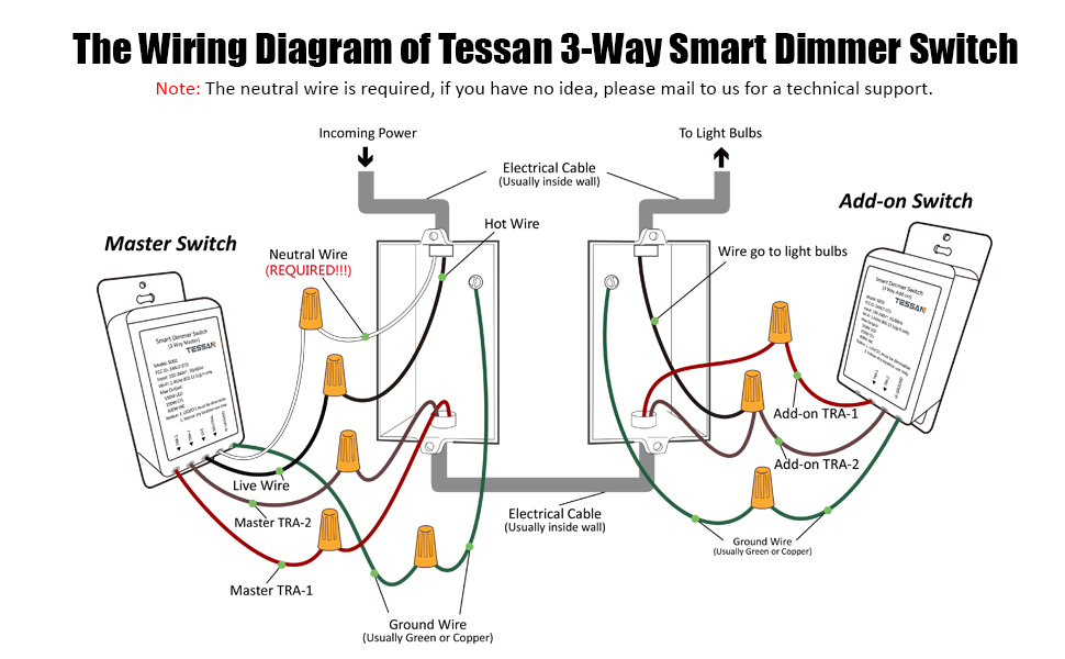
Wiring Diagram for 3-Way Switch with Dimmer: A schematic illustration depicting the electrical connections and component arrangement for controlling lighting from two separate locations with the ability to adjust light intensity.
Example: Installing a 3-way switch with dimmer in a hallway allows for convenient light control from either end, with the dimmer enabling adjustment of brightness to suit the desired ambiance.
Relevance and Benefits: Such wiring diagrams are invaluable for electricians and homeowners alike, facilitating safe and efficient installation of 3-way switches with dimmers, ensuring proper functionality and optimal light control.
Historical Development: The advent of solid-state electronics in the mid-20th century revolutionized lighting control by introducing dimmers, offering the ability to adjust light intensity to suit various needs.
Transition: This article delves into the intricacies of wiring diagrams for 3-way switches with dimmers, exploring their components, configurations, and the practical considerations for successful installation.
Wiring diagrams for 3-way switches with dimmers are crucial for understanding the intricate connections and component arrangements necessary for proper installation and functionality. These diagrams encompass various essential aspects that require careful consideration, ensuring (safety), (efficiency), and optimal light control.
- Components: Switches, dimmers, wires, terminals
- Configurations: Single-pole, 3-way, 4-way
- Circuitry: Parallel, series
- Electrical Codes: NEC, CEC
- Tools: Screwdrivers, wire strippers, voltage tester
- Safety Precautions: Circuit breaker, GFCI
- Troubleshooting: Common issues, solutions
- Lighting Control: Dimming range, compatibility
- Applications: Residential, commercial
Understanding these aspects through detailed wiring diagrams empowers electricians and homeowners alike to confidently install and maintain 3-way switches with dimmers. For example, proper component selection ensures compatibility and durability, while adherence to electrical codes guarantees safety and compliance. Troubleshooting knowledge enables prompt resolution of issues, minimizing downtime and frustration.
Components
In the context of “Wiring Diagram for 3-Way Switch with Dimmer”, understanding the individual components and their interconnections is paramount for successful installation and operation. These components play specific roles, ensuring proper functionality, safety, and control of lighting systems.
-
Switches
3-way switches are designed to control lighting from multiple locations, allowing for convenient switching from different points in a room or hallway. They come in various styles, including rocker, toggle, and touch switches. -
Dimmers
Dimmers regulate the flow of electricity to the lighting fixture, enabling adjustment of light intensity to create desired ambiance or cater to specific tasks. They are available in various types, including rotary, slide, and touch dimmers. -
Wires
Electrical wires serve as the pathways for electricity to flow through the circuit. Proper wire selection is crucial, considering factors such as amperage, voltage, and insulation. Common wire types include copper and aluminum. -
Terminals
Terminals provide secure connections between wires and other components. They are typically made of brass or copper and come in various sizes and shapes to accommodate different wire gauges.
These components work together to form a complete 3-way switch with dimmer circuit. Understanding their functions and proper installation techniques ensures safe and efficient operation of lighting systems, enhancing convenience, energy efficiency, and overall user experience.
Configurations
In the context of “Wiring Diagram for 3-Way Switch with Dimmer”, understanding the different switch configurations – single-pole, 3-way, and 4-way – is critical for designing and installing an effective lighting control system. These configurations determine how switches are connected within a circuit, affecting the number of locations from which a light can be controlled.
Single-pole switches are the most basic type, allowing control of a light from a single location. They are commonly used for simple lighting fixtures, such as a single light bulb in a room. 3-way switches, on the other hand, provide control from two different locations, typically used in hallways or rooms with multiple entrances. 4-way switches extend this control to three or more locations, making them suitable for larger areas or complex lighting arrangements.
The wiring diagram for a 3-way switch with dimmer incorporates both 3-way switches and a dimmer unit. The dimmer unit is wired in place of one of the 3-way switches, allowing for adjustable light intensity. This configuration enables convenient control of lighting from multiple locations with the added flexibility of dimming.
Understanding the relationship between switch configurations and wiring diagrams empowers electricians and homeowners alike to design and install lighting systems that meet their specific needs. Proper configuration ensures efficient and reliable operation of lighting circuits, enhancing convenience, energy efficiency, and overall user experience.
Circuitry
In the context of “Wiring Diagram for 3-Way Switch with Dimmer”, understanding the concepts of parallel and series circuitry is crucial for designing and installing an effective and safe lighting control system. These two types of circuits have distinct characteristics and applications, affecting the overall functionality of the lighting system.
A parallel circuit provides multiple pathways for current to flow, allowing each light fixture to operate independently. This means that if one light bulb burns out or is turned off, the other lights on the circuit will remain unaffected. Parallel circuits are commonly used in residential and commercial buildings for lighting, outlets, and other electrical devices.
In contrast, a series circuit has only one path for current to flow. If any component in a series circuit fails or is turned off, the entire circuit will be disrupted, causing all lights to go out. Series circuits are less common in lighting applications but may be used for special effects or decorative purposes.
In the wiring diagram for a 3-way switch with dimmer, a combination of parallel and series circuits is employed. The switches are wired in series, controlling the flow of electricity to the dimmer unit. The dimmer unit is then wired in parallel with the light fixture, allowing for adjustable light intensity while maintaining independent control from multiple locations.
Understanding the relationship between circuitry and wiring diagrams empowers electricians and homeowners alike to design and install lighting systems that meet their specific needs. Proper circuit design ensures efficient and reliable operation of lighting circuits, enhancing convenience, energy efficiency, and overall user experience.
Electrical Codes
In the context of “Wiring Diagram for 3-Way Switch with Dimmer”, understanding electrical codes and standards is paramount for ensuring the safety and reliability of lighting installations. The National Electrical Code (NEC) and Canadian Electrical Code (CEC) provide comprehensive guidelines for electrical wiring, including specific requirements for 3-way switches with dimmers.
-
Wire Sizing
Electrical codes specify the minimum wire size that can be used for a given amperage and circuit length. This ensures that the wires can safely carry the electrical current without overheating or causing a fire hazard.
-
Circuit Protection
Codes require the use of circuit breakers or fuses to protect electrical circuits from overloads and short circuits. These devices trip when the current exceeds a safe level, preventing damage to the wiring and connected devices.
-
Grounding
Electrical codes mandate the use of grounding wires to provide a low-resistance path for fault currents. This helps prevent electrical shocks and ensures the safe operation of electrical equipment.
-
Switch and Dimmer Compatibility
Codes specify the compatibility requirements between switches, dimmers, and lighting fixtures. This ensures that the components work together properly and do not create safety hazards.
Adhering to electrical codes is not only a legal requirement but also a crucial aspect of ensuring the safety and functionality of electrical systems. By following these guidelines, electricians and homeowners can design and install lighting systems that meet the highest standards of safety and reliability.
Tools
In the context of “Wiring Diagram for 3-Way Switch with Dimmer,” understanding the indispensable role of tools such as screwdrivers, wire strippers, and voltage testers is crucial for successful installation and maintenance. These tools are not mere accessories but essential components that enable precise and safe handling of electrical components and wiring.
Screwdrivers, with their various tip sizes and shapes, are fundamental for tightening and loosening screws that secure electrical components, including switches, dimmers, and wire terminals. Wire strippers, specifically designed to remove insulation from electrical wires, are vital for proper electrical connections. They ensure that the correct amount of insulation is removed, preventing short circuits and ensuring a secure connection.
Voltage testers play a critical role in ensuring safety by detecting the presence of electricity in wires and circuits. Before handling any electrical components, electricians rely on voltage testers to confirm that the circuit is de-energized, minimizing the risk of electrical shocks. Additionally, voltage testers help identify faulty wiring or troubleshoot electrical problems, ensuring the safe operation of lighting systems.
The practical applications of these tools are evident in the step-by-step process of installing a 3-way switch with dimmer. Screwdrivers are used to secure the switches and dimmer unit in place, while wire strippers prepare the wires for proper connections. Voltage testers are employed throughout the process to verify that the circuit is safe to work on. Without these essential tools, the installation and maintenance of 3-way switches with dimmers would be highly challenging and potentially hazardous.
In conclusion, the understanding of “Tools: Screwdrivers, wire strippers, voltage tester” is inextricably linked to the “Wiring Diagram for 3-Way Switch with Dimmer.” These tools are not optional but fundamental components that ensure the safe and efficient installation, maintenance, and troubleshooting of lighting systems. By recognizing their importance and proper usage, electricians and homeowners can confidently handle electrical projects, ensuring the reliable and safe operation of lighting systems.
Safety Precautions
In the context of “Wiring Diagram for 3-Way Switch with Dimmer,” understanding the significance of safety precautions, particularly circuit breakers and GFCIs (Ground Fault Circuit Interrupters), is paramount for ensuring the safe and reliable operation of lighting systems. These devices play a critical role in preventing electrical hazards, protecting both individuals and property from potential harm.
Circuit breakers and GFCIs operate on distinct principles but share the common goal of safeguarding electrical circuits. Circuit breakers protect against overcurrent conditions, which can occur when excessive electrical current flows through a circuit. Overcurrent conditions can lead to overheating, electrical fires, and damage to appliances and devices. Circuit breakers are designed to trip and interrupt the flow of electricity when the current exceeds a predetermined safe level, effectively preventing such hazardous situations.
GFCIs provide protection against ground faults, which occur when electrical current escapes from its intended path and flows through the ground or an unintended conductor. Ground faults can result in electrical shocks, electrocution, and fires. GFCIs are highly sensitive to these conditions and are designed to trip and cut off power within milliseconds of detecting a ground fault, minimizing the risk of harm.
In the context of a 3-way switch with dimmer wiring diagram, circuit breakers and GFCIs are essential components that ensure the safe operation of the lighting system. Circuit breakers are installed in the electrical panel and protect the entire circuit from overcurrent conditions. GFCIs are typically installed near sources of water, such as bathrooms and kitchens, where the risk of ground faults is higher. By incorporating these safety precautions into the wiring diagram, electricians and homeowners can significantly reduce the risk of electrical accidents and ensure the reliable and safe operation of their lighting systems.
Troubleshooting
Understanding troubleshooting techniques is crucial for addressing common issues that may arise in the installation and operation of 3-way switches with dimmers. This aspect of the wiring diagram empowers electricians and homeowners to identify and resolve problems, ensuring the reliable and safe functioning of lighting systems.
-
Loose Connections
Loose connections can disrupt the flow of electricity, causing lights to flicker or fail to operate. Inspecting and tightening all wire connections, including those at switches, dimmers, and light fixtures, often resolves the issue.
-
Faulty Switches or Dimmers
Defective switches or dimmers can interrupt the circuit, preventing lights from turning on or dimming properly. Replacing faulty components with compatible models ensures proper functionality.
-
Overloaded Circuit
Connecting too many lights or appliances to a single circuit can overload it, tripping the circuit breaker or blowing a fuse. Redistributing the electrical load by adding additional circuits or using higher-amperage circuit breakers can resolve the issue.
-
Incorrect Wiring
Incorrect wiring can lead to various problems, including lights not working, flickering, or dimming erratically. Verifying that all wires are connected to the correct terminals and that the circuit is wired according to the wiring diagram ensures proper operation.
By addressing these common issues, troubleshooting empowers individuals to maintain and repair 3-way switch with dimmer systems, ensuring their continued functionality and enhancing the overall safety and convenience of lighting systems.
Lighting Control
In the context of “Wiring Diagram for 3-Way Switch with Dimmer,” understanding the significance of lighting control, particularly the dimming range and compatibility, is crucial for designing and implementing effective lighting systems. The dimming range refers to the minimum and maximum brightness levels that can be achieved using the dimmer, while compatibility ensures that the dimmer is suitable for the specific lighting fixtures and electrical system.
The dimming range of a dimmer is determined by its design and the type of lighting load it is intended to control. Incandescent and halogen lights are widely compatible with most dimmers, offering a smooth and responsive dimming experience. However, other lighting technologies, such as LEDs and fluorescent lights, may require specific types of dimmers to ensure proper operation and avoid flickering or damage to the light source. Choosing a dimmer with an appropriate dimming range ensures that the desired lighting ambiance can be achieved.
Compatibility between the dimmer and lighting fixtures is another critical consideration. Dimmers are designed to work with specific types of lighting loads, such as resistive loads (incandescent and halogen lights) or inductive loads (fluorescent lights and some LED fixtures). Using an incompatible dimmer can lead to poor performance, flickering, or even damage to the lighting fixtures. Verifying the compatibility of the dimmer with the intended lighting load is essential for a successful installation.
By understanding the connection between lighting control, dimming range, and compatibility, electricians and homeowners can select and install the appropriate dimmer for their specific lighting needs. This ensures optimal performance, energy efficiency, and extends the lifespan of both the dimmer and lighting fixtures. Proper dimming control empowers users to adjust the lighting ambiance to suit various activities and moods, enhancing the overall comfort, functionality, and aesthetics of their living spaces.
Applications
The versatility of 3-way switches with dimmers extends their applications to both residential and commercial settings, offering convenient light control and enhancing the ambiance of diverse spaces. These applications encompass various aspects, including:
-
Home Lighting
In residential settings, 3-way switches with dimmers are commonly used in hallways, bedrooms, and living rooms, providing convenient control of lighting from multiple locations while allowing for adjustment of brightness to create the desired atmosphere.
-
Commercial Lighting
In commercial spaces such as offices, retail stores, and restaurants, 3-way switches with dimmers offer flexibility in lighting control. They enable adjustment of light levels to suit specific tasks or ambiance, enhancing productivity, visual comfort, and customer experience.
-
Outdoor Lighting
Outdoor areas like patios, gardens, and pathways can benefit from the use of 3-way switches with dimmers, allowing for convenient control of lighting from different access points and facilitating adjustment of brightness levels to create a welcoming and aesthetically pleasing ambiance.
-
Architectural Lighting
In architectural lighting applications, 3-way switches with dimmers provide precise control over the intensity and distribution of light, enabling the creation of dramatic effects and highlighting specific architectural features to enhance the overall visual appeal of a space.
The widespread applications of 3-way switches with dimmers underscore their versatility and effectiveness in controlling lighting in both residential and commercial settings. By offering convenient control from multiple locations and allowing for adjustment of brightness levels, these switches enhance functionality, create ambiance, and contribute to the overall aesthetics of a space.


Related Posts


