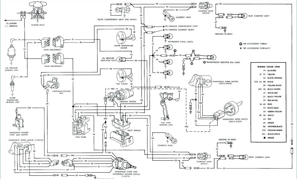
A “Wiring Diagram 1967 Mustang” is a detailed technical drawing that shows the electrical connections and components of a 1967 Ford Mustang automobile. It provides a visual representation of the electrical system, including the wiring harnesses, fuses, relays, switches, and electrical devices. This diagram serves as a comprehensive guide for troubleshooting electrical faults, designing custom electrical systems, and understanding the electrical architecture of the vehicle.
Wiring diagrams are crucial for maintaining and repairing vehicles. They provide technicians with a clear understanding of the electrical system’s layout, enabling them to diagnose and fix electrical problems efficiently. Wiring diagrams also offer benefits for enthusiasts who modify their vehicles’ electrical systems, helping them to integrate new components and ensure proper functionality.
Historically, wiring diagrams were hand-drawn schematics. Today, they are typically created using computer-aided design (CAD) software. This technological advancement has greatly improved the accuracy and clarity of wiring diagrams, making them more accessible and useful for both professionals and hobbyists.
Moving forward, this article will delve deeper into the key elements of a Wiring Diagram 1967 Mustang, exploring its significance for electrical troubleshooting, vehicle maintenance, and automotive enthusiasts.
Wiring diagrams are essential for understanding and maintaining the electrical systems of vehicles. In the case of a 1967 Mustang, a wiring diagram provides a detailed visual representation of the electrical connections and components, enabling troubleshooting, repairs, and modifications. The key aspects of a Wiring Diagram 1967 Mustang encompass various dimensions, exploring the diagram’s components, functionality, and significance:
- Electrical Components: The diagram identifies and locates all electrical components, such as lights, switches, relays, and motors, providing a comprehensive overview of the system.
- Wiring Harnesses: It illustrates the pathways of electrical wiring harnesses, showing how they connect different components and distribute power throughout the vehicle.
- Circuit Protection: The diagram indicates the location of fuses and circuit breakers, which protect the electrical system from overloads and short circuits.
- Ground Connections: It shows the grounding points in the electrical system, ensuring proper completion of electrical circuits.
- Color Coding: Wiring diagrams use color coding to differentiate between different types of wires, simplifying the identification and tracing of electrical connections.
- Legend and Symbols: The diagram includes a legend that explains the symbols and abbreviations used, making it easier to understand the diagram’s content.
- Troubleshooting Guide: Some wiring diagrams incorporate troubleshooting guides, providing step-by-step instructions for diagnosing and resolving electrical faults.
- Historical Context: The diagram reflects the electrical system design of the 1967 Mustang, offering insights into the evolution of automotive electrical systems.
- Customization Potential: For enthusiasts modifying their Mustangs, the wiring diagram serves as a guide for integrating new electrical components and customizing the electrical system.
- Maintenance and Repair: It aids in diagnosing electrical problems, repairing faulty components, and maintaining the electrical system’s integrity.
In conclusion, Wiring Diagrams 1967 Mustang are invaluable resources for understanding, troubleshooting, and modifying the electrical systems of these classic vehicles. They provide a comprehensive visual representation of the electrical components, connections, and circuitry, empowering mechanics, enthusiasts, and owners to maintain, repair, and enhance their Mustangs.
Electrical Components
Within the intricate network of a Wiring Diagram 1967 Mustang, the identification and location of electrical components hold paramount importance. This aspect of the diagram serves as a guiding map, pinpointing the position of each electrical entity within the vehicle’s electrical system.
- Lights: The diagram meticulously illustrates the placement of various lighting components, including headlights, taillights, brake lights, turn signals, and interior lights. This information is crucial for troubleshooting lighting issues, ensuring optimal visibility and safety during operation.
- Switches: The diagram precisely locates all switches, such as ignition switches, headlight switches, and window switches. Understanding their positions enables efficient diagnosis and replacement of faulty switches, ensuring smooth control over various electrical functions.
- Relays: Relays serve as intermediaries between electrical components, controlling the flow of current. The diagram clearly indicates the location of relays, facilitating their inspection, testing, and replacement when necessary. This knowledge empowers individuals to maintain optimal electrical system performance.
- Motors: The diagram comprehensively outlines the positioning of motors, including the starter motor, wiper motor, and blower motor. This information aids in diagnosing motor-related issues, ensuring efficient operation of essential vehicle functions such as starting, visibility, and climate control.
In summary, the identification and location of electrical components in a Wiring Diagram 1967 Mustang provide a comprehensive understanding of the vehicle’s electrical system. By pinpointing the exact placement of each component, the diagram empowers individuals to troubleshoot problems, perform repairs, and modify the electrical system with confidence.
Wiring Harnesses
Within the intricate web of a Wiring Diagram 1967 Mustang, the depiction of wiring harnesses holds immense significance. These harnesses serve as the circulatory system of the vehicle’s electrical network, meticulously connecting various components and ensuring the seamless distribution of electrical power.
The diagram illustrates the pathways of these wiring harnesses with remarkable precision. Each harness is meticulously traced, showing its origin, destination, and the components it interconnects. This detailed representation empowers individuals to comprehend the electrical system’s architecture, trace electrical faults, and modify the system as per their requirements.
For instance, consider the task of installing an aftermarket sound system in a 1967 Mustang. The Wiring Diagram 1967 Mustang provides crucial insights into the existing wiring harnesses, enabling the installer to identify suitable connection points and avoid potential conflicts. This understanding ensures a seamless integration of the new system without compromising the integrity of the original electrical architecture.
Furthermore, the diagram’s depiction of wiring harnesses facilitates the diagnosis and repair of electrical issues. By tracing the pathways of harnesses, technicians can pinpoint the exact location of a fault, reducing troubleshooting time and minimizing unnecessary component replacements. This practical application underscores the importance of understanding wiring harnesses within the context of a Wiring Diagram 1967 Mustang.
In summary, the illustration of wiring harnesses in a Wiring Diagram 1967 Mustang is not merely a technical detail but a critical element that empowers individuals to comprehend, modify, and maintain the vehicle’s electrical system. It provides a roadmap for navigating the intricate network of electrical connections, enabling effective troubleshooting, system upgrades, and overall electrical system management.
Circuit Protection
Within the intricate network of a Wiring Diagram 1967 Mustang, the aspect of circuit protection stands out as a crucial element, ensuring the safety and reliability of the vehicle’s electrical system. This aspect of the diagram plays a pivotal role in preventing electrical overloads and short circuits, which could lead to catastrophic consequences such as fires or extensive damage to electrical components.
- Fuses: Fuses serve as sacrificial devices within the electrical system. They contain a thin wire designed to melt and break the circuit when excessive current flows, thereby protecting other components from damage. The Wiring Diagram 1967 Mustang meticulously indicates the location and amperage rating of each fuse, empowering individuals to quickly identify and replace blown fuses, restoring electrical functionality.
- Circuit Breakers: Circuit breakers function as reusable protective devices. Unlike fuses, they can be manually reset after tripping due to an overload. The diagram precisely illustrates the placement of circuit breakers within the electrical system, enabling individuals to locate and reset them as needed. This feature provides added convenience and reduces the need for frequent fuse replacements.
- Overload Protection: Circuit protection measures safeguard the electrical system from overloads, which occur when excessive current flows through a circuit. The diagram’s indication of fuse and circuit breaker locations empowers individuals to identify potential overload risks and implement appropriate corrective actions.
- Short Circuit Protection: Short circuits arise when an unintended path of low resistance is created, allowing excessive current to flow. The diagram’s precise depiction of circuit protection devices enables individuals to locate and short circuits, preventing potential damage to the electrical system and its components.
In summary, the Circuit Protection aspect of a Wiring Diagram 1967 Mustang is of paramount importance, providing a visual guide to the location and functionality of fuses and circuit breakers. Understanding and utilizing this information empowers individuals to maintain a safe and reliable electrical system, preventing costly repairs and ensuring the optimal performance of their 1967 Mustang.
Ground Connections
Within the intricate network of a Wiring Diagram 1967 Mustang, the grounding connections play a crucial role, ensuring the proper completion of electrical circuits and the safe and reliable operation of the vehicle’s electrical system. Grounding connections provide a conductive path to allow the flow of electrical current back to the negative terminal of the battery, completing the circuit and enabling the various electrical components to function correctly.
The Wiring Diagram 1967 Mustang meticulously illustrates the location of grounding points throughout the electrical system. These grounding points are typically connected to the vehicle’s chassis or frame, which acts as a common ground reference for all electrical components. By providing a low-resistance path for electrical current to return to the battery, grounding connections prevent voltage fluctuations, ensure stable electrical performance, and protect against electrical faults.
For instance, consider the electrical circuit for the headlights of a 1967 Mustang. The positive terminal of the battery is connected to the headlight switch, which, when turned on, completes the circuit by providing a path for current to flow through the headlights and back to the negative terminal of the battery. The Wiring Diagram 1967 Mustang would clearly indicate the grounding point for this circuit, typically located on the vehicle’s chassis near the headlights. This grounding point provides a crucial connection, ensuring that the electrical current can complete its circuit and illuminate the headlights properly.
In summary, the grounding connections depicted in a Wiring Diagram 1967 Mustang are essential for the proper functioning of the vehicle’s electrical system. Understanding the location and importance of these grounding points empowers individuals to troubleshoot electrical issues, modify the electrical system, and ensure the safety and reliability of their 1967 Mustang.
Color Coding
In the context of a Wiring Diagram 1967 Mustang, color coding plays a critical role in simplifying the identification and tracing of electrical connections. Wiring diagrams utilize a standardized color-coding scheme to differentiate between various types of wires, enabling individuals to quickly and accurately identify the function and destination of each wire.
For instance, in a Wiring Diagram 1967 Mustang, red wires typically indicate power wires, black wires represent ground wires, and blue wires are commonly used for lighting circuits. This color-coding convention provides a visual cue, reducing the need for extensive tracing and guesswork when troubleshooting electrical issues or modifying the electrical system.
The practical application of color coding within a Wiring Diagram 1967 Mustang extends beyond simplified identification. It also enhances the efficiency of electrical repairs and modifications. By quickly identifying the type and function of a wire based on its color, individuals can swiftly locate and address electrical faults, saving time and effort.
Furthermore, the standardized color-coding scheme facilitates the integration of aftermarket components and accessories into the electrical system of a 1967 Mustang. By adhering to the established color-coding convention, individuals can confidently connect new electrical components without compromising the integrity or safety of the original wiring.
In summary, color coding in a Wiring Diagram 1967 Mustang serves as a crucial tool for understanding, troubleshooting, and modifying the vehicle’s electrical system. The standardized color-coding scheme simplifies the identification and tracing of electrical connections, enhancing the efficiency and accuracy of electrical repairs and modifications.
Legend and Symbols
Within the intricate network of a Wiring Diagram 1967 Mustang, the inclusion of a legend and symbols plays a pivotal role in deciphering the diagram’s content. This aspect provides a comprehensive guide to the various symbols and abbreviations employed throughout the diagram, enabling individuals to comprehend its intricacies and accurately interpret the electrical system’s design.
- Symbol Representation: The legend clearly defines the graphical symbols used to represent different electrical components, such as batteries, switches, resistors, and transistors. This visual language simplifies the identification of components and facilitates a quick understanding of the electrical system’s layout.
- Abbreviation Explanation: The diagram often incorporates abbreviations to denote specific electrical terms or components. The legend provides a comprehensive list of these abbreviations and their corresponding meanings, allowing individuals to decode the diagram’s technical language.
- Color Coding Correlation: In conjunction with color coding, the legend may also indicate the color scheme used for different types of wires, ensuring a consistent and intuitive approach to tracing electrical connections throughout the diagram.
- Real-Life Examples: To further enhance clarity, the legend often includes real-life examples or illustrations that demonstrate the practical application of symbols and abbreviations within the context of the electrical system.
The legend and symbols in a Wiring Diagram 1967 Mustang serve as a critical bridge between the diagram’s technical representation and the user’s understanding. By providing a clear and concise explanation of the symbols and abbreviations used, the legend empowers individuals to navigate the diagram with confidence, troubleshoot electrical issues effectively, and make informed modifications to the electrical system.
Troubleshooting Guide
Within the context of “Wiring Diagram 1967 Mustang”, the incorporation of a troubleshooting guide holds significant importance. A troubleshooting guide provides a structured and methodical approach to diagnosing and resolving electrical faults within the vehicle’s electrical system.
The troubleshooting guide typically includes a series of step-by-step instructions, guiding the individual through a logical process of elimination to identify the root cause of the electrical fault. This structured approach enables even novice users to troubleshoot electrical issues with greater confidence and efficiency.
For instance, consider a scenario where the headlights of a 1967 Mustang fail to illuminate. The troubleshooting guide would provide a systematic procedure to isolate the fault. It might begin by instructing the user to check the headlight switch, followed by the fuses and relays associated with the headlight circuit. By following the guide’s instructions, the user can methodically eliminate potential causes until the actual fault is identified.
The presence of a troubleshooting guide in a “Wiring Diagram 1967 Mustang” empowers individuals to address electrical issues independently. It reduces the need for costly professional assistance and promotes self-sufficiency in vehicle maintenance.
In conclusion, the incorporation of a troubleshooting guide within a “Wiring Diagram 1967 Mustang” provides a valuable tool for diagnosing and resolving electrical faults. Its step-by-step instructions simplify the troubleshooting process, enabling users to maintain and repair their vehicles with greater confidence and efficiency.
Historical Context
The Wiring Diagram 1967 Mustang is not merely a technical document; it is a historical artifact that provides valuable insights into the evolution of automotive electrical systems. By examining the diagram, we can trace the development of electrical components, circuit design, and troubleshooting techniques used in the mid-20th century.
The 1967 Mustang was a revolutionary vehicle, embodying the spirit of innovation and technological advancement. Its electrical system reflected the latest trends in automotive engineering, showcasing the transition from simple electrical circuits to more complex and sophisticated systems.
The diagram reveals the intricate network of wires, fuses, switches, and relays that worked together to power the Mustang’s electrical components. It illustrates the use of color-coding to differentiate between different types of wires, a practice that has become standard in modern automotive electrical systems.
Furthermore, the diagram provides a glimpse into the troubleshooting techniques used by mechanics in the 1960s. It includes a legend that explains the symbols and abbreviations used in the diagram, making it easier for users to identify and diagnose electrical faults.
In conclusion, the Wiring Diagram 1967 Mustang offers a unique opportunity to explore the historical context of automotive electrical systems. By understanding the design principles and troubleshooting techniques used in the mid-20th century, we can appreciate the significant advancements that have been made in the field of automotive electronics.
Customization Potential
The Wiring Diagram 1967 Mustang provides a wealth of information not only for troubleshooting and maintaining the original electrical system but also for those seeking to customize and modify their Mustangs. This diagram serves as a roadmap for integrating new electrical components, enabling enthusiasts to enhance the functionality and appearance of their vehicles.
- Component Integration: The diagram provides a clear understanding of the existing electrical system, allowing enthusiasts to identify suitable connection points for new components such as aftermarket stereos, performance ignition systems, and auxiliary lighting. By referring to the diagram, they can avoid potential conflicts and ensure proper integration.
- Electrical System Expansion: The diagram facilitates the expansion of the electrical system to accommodate additional features and accessories. For instance, enthusiasts can use it to plan the wiring for a custom sound system, install driving lights, or add a remote start system.
- Circuit Modifications: The diagram empowers enthusiasts to modify existing circuits to achieve specific outcomes. This could involve altering lighting circuits for custom taillight configurations, adjusting charging circuits for higher output alternators, or installing relays to improve electrical performance.
- Troubleshooting and Compatibility: When incorporating new electrical components, the wiring diagram serves as a valuable tool for troubleshooting and ensuring compatibility. By comparing the diagram to the new component’s wiring instructions, enthusiasts can identify potential issues and make necessary adjustments for seamless integration.
In summary, the Wiring Diagram 1967 Mustang is not just a maintenance and repair guide but also a valuable resource for enthusiasts seeking to customize and enhance their Mustangs. It empowers them to integrate new electrical components, expand the electrical system, modify circuits, and troubleshoot compatibility issues, ultimately allowing them to tailor their vehicles to their specific needs and preferences.
Maintenance and Repair
The Wiring Diagram 1967 Mustang serves not only as a guide for troubleshooting electrical issues but also as a valuable tool for maintaining and repairing the electrical system. It empowers individuals to diagnose electrical problems accurately, repair faulty components efficiently, and ensure the overall integrity of the electrical system, contributing to the optimal performance and longevity of their 1967 Mustang.
- Electrical Diagnostics: The wiring diagram provides a visual representation of the electrical system, enabling individuals to trace electrical circuits, identify potential faults, and pinpoint the root cause of electrical problems. This facilitates targeted repairs and reduces the time and effort spent on troubleshooting.
- Component Replacement: The diagram includes a comprehensive list of electrical components and their locations, allowing individuals to easily identify and replace faulty components. By referring to the diagram, individuals can ensure that the correct replacement components are used, ensuring proper functionality and compatibility with the existing electrical system.
- System Integrity: The wiring diagram serves as a reference for maintaining the integrity of the electrical system over time. By regularly inspecting the diagram and comparing it to the actual electrical system, individuals can identify potential issues such as loose connections, damaged wires, or corrosion, enabling timely repairs and preventive maintenance.
- Modifications and Upgrades: For individuals seeking to modify or upgrade their electrical system, the wiring diagram provides a solid foundation for planning and executing changes safely and efficiently. By understanding the existing electrical architecture, individuals can make informed decisions about adding new components or modifying existing circuits, ensuring compatibility and maintaining the overall integrity of the electrical system.
In summary, the Wiring Diagram 1967 Mustang is an essential tool for maintaining and repairing the electrical system of a 1967 Mustang. It empowers individuals to diagnose electrical problems accurately, replace faulty components efficiently, ensure the overall integrity of the electrical system, and make informed decisions about modifications and upgrades, contributing to the optimal performance, safety, and longevity of their classic Mustang.


Related Posts


