A wiring backup camera is a camera system that provides the driver with an enhanced view of the area behind their vehicle, attached to the reverse lights in order to activate automatically when the car is in reverse. A common example is a small, waterproof camera that can be mounted on the rear license plate or bumper and connected to a display screen on the dashboard.
Backup cameras are significant because they extend the driver’s line of vision, making it easier and safer to maneuver in tight spaces. They provide benefits such as reduced blind spots, enhanced situational awareness, and increased pedestrian safety. A key historical development in backup cameras was the introduction of wireless systems, which eliminated the need for complex wiring and made installation more accessible for consumers.
In this article, we will explore the technical aspects of wiring backup cameras, providing step-by-step instructions, troubleshooting tips, and advanced configuration options. By understanding the wiring process, readers can enhance the safety and functionality of their backup cameras, contributing to a more informed and prepared driving experience.
Wiring a backup camera is a crucial aspect of ensuring its proper functionality and enhancing the safety features of a vehicle. Understanding the essential aspects of wiring a backup camera empowers individuals to make informed decisions and execute the installation process effectively.
- Camera Selection: Choosing the right camera for your vehicle’s specific needs.
- Power Supply: Determining the power source and wiring it correctly to the camera.
- Display Connection: Connecting the camera to the display screen or monitor.
- Reverse Trigger: Wiring the camera to activate automatically when the vehicle is in reverse.
- Grounding: Establishing a proper ground connection for the camera.
- Wire Management: Concealing and securing the wires for a clean and professional installation.
- Soldering and Crimping: Techniques for creating reliable electrical connections.
- Troubleshooting: Diagnosing and resolving common wiring issues.
- Advanced Features: Exploring additional wiring options for features such as grid lines and night vision.
- Safety Precautions: Ensuring proper handling and installation to avoid electrical hazards.
These aspects are interconnected and play vital roles in the successful operation of a backup camera system. By understanding and addressing each aspect carefully, individuals can enhance the safety and convenience of their driving experience.
Camera Selection
Camera selection is a fundamental aspect of wiring a backup camera system. Choosing the right camera ensures optimal performance, compatibility with your vehicle, and alignment with your specific requirements. Here are a few key factors to consider when selecting a backup camera:
- Resolution: The resolution of a backup camera determines the clarity and sharpness of the image it produces. Higher resolution cameras provide better image quality and allow for easier identification of objects and details.
- Field of View: The field of view refers to the area that the camera can capture. A wider field of view provides a more comprehensive view of the surroundings, while a narrower field of view focuses on a smaller area with more detail.
- Mounting Options: Backup cameras come with different mounting options, such as license plate mounts, bumper mounts, and tailgate mounts. Choose a camera with a mounting option that is compatible with your vehicle and your desired placement.
- Night Vision: If you frequently drive in low-light conditions or at night, consider a backup camera with night vision capabilities. Night vision cameras use infrared technology to provide clear images even in darkness.
By carefully considering these factors, you can select a backup camera that meets the specific needs of your vehicle and driving habits. A well-chosen camera will enhance your situational awareness, improve safety, and provide peace of mind while reversing or maneuvering in tight spaces.
Power Supply
When wiring a backup camera, determining the power source and wiring it correctly to the camera is a fundamental aspect that ensures reliable operation and longevity of the system. This involves identifying a suitable power source, understanding the electrical requirements of the camera, and establishing a secure and stable connection.
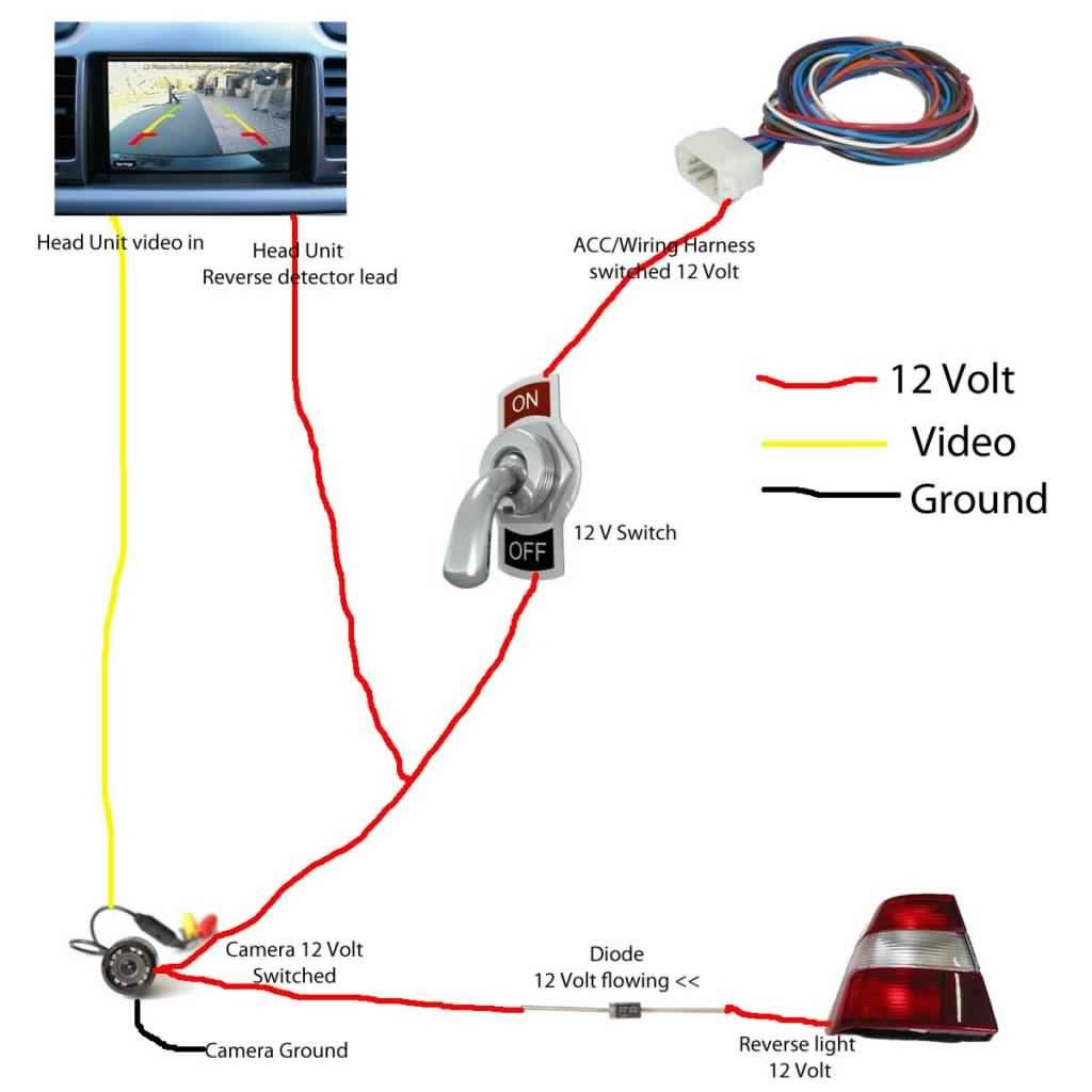
- Power Source Selection: Choosing the right power source for the backup camera is crucial. Common options include the vehicle’s reverse light circuit, a dedicated 12-volt power outlet, or the vehicle’s battery. Each option has its own advantages and considerations, such as availability, ease of access, and potential impact on other electrical systems.
- Electrical Compatibility: Before connecting the camera to the power source, it is essential to verify its electrical compatibility. This includes matching the camera’s voltage requirements with the power source’s output, as well as ensuring that the camera’s current draw does not exceed the power source’s capacity.
- Wiring Harness: Most backup cameras come with a wiring harness that includes the necessary cables and connectors. Proper installation of the wiring harness involves connecting the power wires to the power source, the ground wire to a suitable grounding point on the vehicle’s chassis, and the video cable to the display unit.
- Soldering and Crimping: For secure and reliable connections, soldering or crimping the electrical connections is recommended. Soldering provides a permanent bond between the wires, while crimping involves using specialized connectors to create a secure mechanical connection. Both methods ensure a low-resistance path for electrical current and prevent loose connections.
Understanding and addressing these aspects of power supply and wiring are essential for a properly functioning backup camera system. By carefully selecting the power source, ensuring electrical compatibility, installing the wiring harness correctly, and employing proper connection techniques, you can ensure that your backup camera operates reliably and enhances your driving safety.
Display Connection
Display connection is an integral aspect of wiring a backup camera, as it enables the transmission of video signals from the camera to a display screen or monitor within the vehicle. This connection plays a pivotal role in providing the driver with a clear and real-time view of the area behind the vehicle, enhancing safety and convenience during reversing and parking maneuvers.
- Display Options: Backup cameras can be connected to various display options, including dedicated monitors mounted on the dashboard or integrated screens within the vehicle’s infotainment system. Choosing the right display depends on factors such as screen size, resolution, and compatibility with the camera.
- Video Signal: The video signal from the backup camera is typically transmitted using RCA cables or wirelessly via Bluetooth or Wi-Fi. Understanding the type of video signal supported by the camera and display is crucial for proper connection and image quality.
- Cable Management: When using wired connections, careful attention must be paid to cable management. The video cable should be routed securely to avoid tangling, damage, or interference with other electrical components in the vehicle.
- Troubleshooting: If the display is not receiving a signal from the camera, troubleshooting steps may involve checking the connections, power supply, and compatibility of the components. Proper troubleshooting ensures a reliable and functional display connection.
By understanding and addressing the various aspects of display connection, individuals can ensure that their backup camera system operates effectively, providing them with enhanced visibility and safety while reversing. A properly connected display allows drivers to make informed decisions and navigate their vehicles confidently in various driving situations.
Reverse Trigger
Within the comprehensive process of “Wiring Backup Camera”, reverse trigger plays a crucial role in ensuring the seamless and timely activation of the camera. This aspect involves wiring the camera to the vehicle’s reverse light circuit, enabling it to automatically engage when the vehicle is shifted into reverse gear. This functionality greatly enhances safety and convenience during reversing maneuvers.
- Trigger Wire: The trigger wire, typically connected to the reverse light circuit, sends a signal to the camera, activating it when the vehicle is in reverse.
- Relay: In some cases, a relay may be used to isolate the camera from the vehicle’s electrical system, providing additional protection and preventing electrical interference.
- Delay Timer: A delay timer can be incorporated to prevent the camera from activating momentarily when the reverse gear is engaged, ensuring its activation only when the vehicle is actually reversing.
- Compatibility: Compatibility between the camera and the vehicle’s electrical system is essential, as mismatched components can lead to malfunctions or damage.
Understanding and addressing these facets of reverse trigger are crucial for a properly functioning backup camera system. By ensuring proper wiring, selecting compatible components, and incorporating additional features such as delay timers, individuals can maximize the effectiveness and reliability of their backup cameras, enhancing their safety and driving experience.
Grounding
Proper grounding is a critical aspect of “Wiring Backup Camera” as it ensures a complete electrical circuit and prevents potential malfunctions or safety hazards. Without a proper ground connection, the camera may not function correctly or may introduce electrical noise into the vehicle’s electrical system.
- Chassis Ground: The metal frame or body of the vehicle provides a suitable grounding point. Connecting the camera’s ground wire to the chassis establishes a direct path for electrical current to flow back to the vehicle’s battery, completing the circuit.
- Dedicated Grounding Point: Some vehicles may have dedicated grounding points specifically designed for aftermarket electrical accessories. Using these designated points ensures a secure and reliable ground connection.
- Ground Loop Avoidance: Improper grounding can create ground loops, which are paths for electrical current to flow unintentionally. Ground loops can cause interference, noise, or even damage to electrical components. Proper grounding techniques help prevent ground loops by ensuring a single, well-defined path for electrical current to flow.
- Safety Considerations: A proper ground connection is essential for safety. Without it, electrical faults or shorts may occur, potentially leading to electrical fires or damage to the vehicle’s electrical system.
Understanding and addressing grounding ensures a stable and reliable electrical connection for the backup camera. By establishing a proper ground connection, individuals can enhance the overall functionality and safety of their backup camera system, ensuring a secure and clear view while reversing their vehicles.
Wire Management
Wire Management: Concealing and securing the wires for a clean and professional installation is a critical aspect of Wiring Backup Camera that contributes to the overall aesthetics, functionality, and longevity of the system. Proper wire management ensures that the wiring is organized, protected, and concealed, enhancing the reliability and safety of the backup camera.
- Routing and Bundling: Wires should be routed along existing wire harnesses or tucked away in designated channels to maintain a tidy and organized appearance. Bundling multiple wires together using cable ties or wire looms helps reduce clutter and prevent tangles.
- Protection and Insulation: Wires should be protected from potential damage caused by heat, moisture, or mechanical stress. This can be achieved using wire loom tubing, heat shrink tubing, or electrical tape, which provide insulation and protection against abrasion.
- Grounding and Shielding: Proper grounding ensures a stable electrical connection and prevents electrical noise. Shielding, such as braided shielding or foil tape, can minimize electromagnetic interference, improving signal quality and reducing potential interference with other electrical components.
- Accessibility and Maintenance: Wires should be accessible for future maintenance or troubleshooting. Leaving some slack in the wiring and using quick-disconnect connectors or terminal blocks allows for easy access and serviceability if needed.
By implementing these wire management techniques, individuals can ensure that their backup camera system is not only functional but also aesthetically pleasing and durable. Proper wire management contributes to a clean and professional installation, enhances the reliability of the system, and provides peace of mind knowing that the wiring is organized, protected, and accessible for future maintenance.
Soldering and Crimping
In the context of “Wiring Backup Camera”, soldering and crimping are fundamental techniques for creating reliable and secure electrical connections. These methods ensure proper signal transmission, power distribution, and overall system functionality.
-
Soldering: A process of joining electrical wires using a metal alloy with a lower melting point than the wires themselves. Solder creates a strong, permanent bond that ensures uninterrupted current flow.
Example: Joining camera wires to extension cables for a seamless connection. -
Crimping: A technique that involves using a specialized tool to compress a metal connector (ferrule) onto the stripped end of a wire. This creates a secure mechanical bond that prevents wire fraying and ensures a consistent electrical connection.
Example: Connecting camera wires to terminals on the display unit. -
Heat Shrink Tubing: A protective covering that is placed over soldered or crimped connections and then heated to shrink and provide insulation, strain relief, and environmental protection.
Example: Covering soldered wire joints to prevent short circuits and moisture damage. -
Wire Strippers: A tool used to remove the insulation from the ends of wires, exposing the bare metal for soldering or crimping.
Example: Stripping the insulation from camera wires to prepare them for connection.
By mastering these techniques and applying them meticulously, individuals can ensure that their backup camera systems operate optimally, providing a clear and reliable view for safe and convenient reversing maneuvers. Soldering and crimping form the backbone of reliable electrical connections, contributing to the overall effectiveness and longevity of the backup camera system.
Troubleshooting
In the context of “Wiring Backup Camera,” troubleshooting plays a crucial role in ensuring a properly functioning system. It involves identifying and resolving common wiring issues that may arise during installation or usage, ensuring a reliable and safe backup camera experience.
-
Electrical Continuity:
Verifying the electrical continuity of wires and connections is essential. Broken or loose wires can disrupt signal transmission and cause malfunctions. Using a multimeter to test continuity helps identify and rectify such issues.
-
Power Supply:
The power supply to the backup camera must be adequate and stable. Insufficient voltage or faulty wiring can lead to intermittent operation or complete failure. Checking the power source and wiring connections ensures a reliable power supply.
-
Grounding:
Proper grounding is crucial for eliminating electrical noise and ensuring a stable electrical circuit. Loose or improperly grounded connections can cause interference or even damage to the camera. Verifying and securing the grounding points is essential.
-
Signal Transmission:
Inspecting the video signal transmission is vital. Faulty cables, loose connections, or interference can result in poor image quality or signal loss. Testing the signal transmission using a monitor or signal tester helps identify and resolve these issues.
By understanding and addressing these common wiring issues, individuals can effectively troubleshoot and maintain their backup camera systems. Troubleshooting empowers them to identify and resolve problems, ensuring a clear and reliable view for safe and convenient reversing maneuvers.
Advanced Features
As you delve into the intricacies of “Wiring Backup Camera,” it is essential to recognize the significance of “Advanced Features” in enhancing the functionality and practicality of your backup camera system. These advanced features, such as grid lines and night vision, offer a range of benefits that elevate the safety and convenience of reversing maneuvers.
Grid lines, superimposed on the camera’s display, provide visual cues that assist in gauging distances and accurately aligning your vehicle when parking or reversing in tight spaces. This feature is particularly valuable for novice drivers or those navigating unfamiliar environments. Night vision, on the other hand, employs specialized sensors and illumination techniques to enhance visibility in low-light conditions, ensuring clear and reliable images even in darkness.
Incorporating these advanced features into your backup camera system requires additional wiring considerations. Grid lines, for instance, may require a dedicated trigger wire to activate the overlay when the vehicle is in reverse. Night vision systems, with their increased power consumption, may necessitate upgrades to the power supply and wiring harness to ensure stable operation. Understanding these wiring requirements and implementing them correctly are crucial for unlocking the full potential of your backup camera.
By embracing advanced features and addressing the associated wiring needs, you not only enhance the functionality of your backup camera but also make reversing maneuvers safer and more convenient. These features provide valuable assistance in various driving scenarios, contributing to a more informed and confident driving experience.
Safety Precautions
In the context of “Wiring Backup Camera,” safety precautions play a paramount role in preventing electrical hazards and ensuring a safe and reliable installation. These precautions encompass proper handling, meticulous installation techniques, and adherence to electrical codes, all of which are critical components of a successful backup camera wiring project.
Neglecting safety precautions can lead to a range of electrical hazards, including short circuits, electrical fires, and damage to the backup camera system or vehicle’s electrical components. For instance, improper wire connections, inadequate insulation, or incorrect grounding can create electrical pathways that could potentially cause a short circuit, resulting in a sudden and uncontrolled flow of electricity. Moreover, electrical fires can occur when overheated wires ignite surrounding materials, posing a significant safety risk.
Real-life examples underscore the importance of safety precautions during backup camera wiring. In one instance, a loose connection between the camera and the display unit led to intermittent signal loss and flickering images. Upon inspection, it was discovered that the connection had not been properly secured, causing the wires to come into contact with each other and create a short circuit. In another case, a backup camera was installed without proper grounding, resulting in electrical interference that affected the vehicle’s navigation system and caused it to malfunction.
By understanding and implementing safety precautions, individuals can mitigate these risks and ensure the safe and effective operation of their backup camera systems. Adhering to electrical codes, using high-quality materials, and employing proper wiring techniques are essential practices that contribute to a reliable and hazard-free installation. Moreover, regular maintenance and inspection of the backup camera system, including periodic checks of connections and insulation, can help prevent potential problems and ensure continued safe operation.


Related Posts


