Wiring a volt gauge involves connecting it to an electrical system, usually in a vehicle or other device, to monitor voltage. It measures the electrical potential difference, or voltage, across two points in the circuit.
Volt gauges are essential for monitoring battery health, diagnosing electrical issues, and ensuring proper system functioning. They provide real-time information on the voltage levels, allowing for timely adjustments or repairs to prevent damage.
Historically, mechanical volt gauges were used, but modern digital volt gauges offer increased accuracy and precision. They can be connected to various circuits to monitor specific voltage levels, such as the battery voltage in a vehicle.
When wiring a volt gauge, it is crucial to consider several key aspects to ensure accurate voltage monitoring and avoid potential electrical hazards.
- Wire Gauge: The thickness of the wires used to connect the volt gauge should be appropriate for the amount of current flowing through the circuit.
- Wire Type: The type of wire used should be suitable for the application, considering factors like temperature resistance and insulation.
- Connection Points: The volt gauge should be connected to the correct points in the circuit to accurately measure the voltage.
- Polarity: The positive and negative terminals of the volt gauge must be connected to the corresponding terminals of the circuit.
- Grounding: Proper grounding of the volt gauge is essential for accurate readings and safety.
- Calibration: Volt gauges should be calibrated regularly to ensure accuracy.
- Display Type: Analog or digital volt gauges have different display types, each with its advantages and disadvantages.
- Range and Resolution: The volt gauge’s range and resolution should be appropriate for the intended application.
- Protection Features: Consider using volt gauges with built-in protection features like overload protection or reverse polarity protection.
- Safety Precautions: Always follow proper safety precautions when working with electrical circuits and volt gauges.
Understanding these aspects is crucial for proper wiring and utilization of volt gauges in various electrical systems, ensuring reliable voltage monitoring and potential issue identification.
Wire Gauge
When wiring a volt gauge, selecting the correct wire gauge is crucial for ensuring accurate voltage measurements and preventing electrical hazards. The thickness of the wires should be appropriate for the amount of current flowing through the circuit to avoid excessive voltage drop or overheating.
- Conductor Material: The type of conductor material, such as copper or aluminum, impacts the wire’s resistance and current-carrying capacity.
- Wire Size: The wire gauge, expressed in American Wire Gauge (AWG), determines the cross-sectional area of the wire and its ability to carry current.
- Circuit Current: The maximum current expected to flow through the circuit should be considered to select a wire gauge that can handle the load without overheating.
- Wire Length: Longer wires have higher resistance, which can lead to voltage drop. The wire gauge should be selected to minimize voltage loss over the length of the circuit.
Using the appropriate wire gauge is essential for proper volt gauge operation. Insufficient wire gauge can result in inaccurate readings, voltage drop, or even safety hazards due to overheating. Conversely, excessively thick wires may be unnecessary and increase cost. Understanding these factors ensures the selection of the optimal wire gauge for accurate and safe volt gauge wiring.
Wire Type
In the context of wiring a volt gauge, selecting the appropriate wire type is crucial for ensuring accurate voltage measurements and long-term reliability. Different types of wires exhibit varying characteristics, and choosing the right one depends on the specific application and environmental conditions.
- Conductor Material: The type of metal used for the wire’s conductor, such as copper or aluminum, affects its conductivity, resistance, and durability.
- Insulation: The insulating material surrounding the conductor determines the wire’s resistance to heat, moisture, and chemicals, ensuring electrical safety and preventing short circuits.
- Stranding: Stranded wires, composed of multiple thin strands, offer greater flexibility and are less prone to breakage compared to solid wires.
- Shielding: Shielded wires incorporate an additional layer of conductive material around the insulation to minimize electromagnetic interference (EMI) and ensure signal integrity.
Considering these factors, selecting the appropriate wire type for wiring a volt gauge is essential for accurate measurements and reliable performance. Improper wire selection can lead to inaccurate readings, signal degradation, or even safety hazards due to overheating or insulation failure.
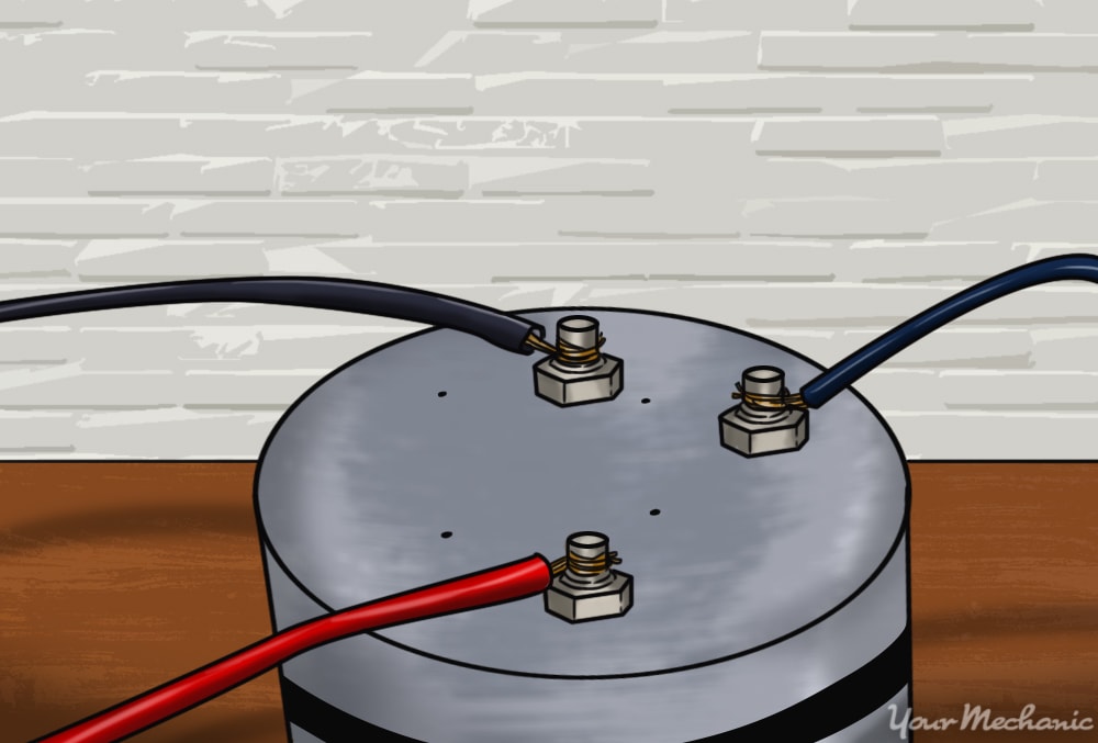
Connection Points
When wiring a volt gauge, selecting the appropriate connection points is paramount for obtaining accurate voltage measurements. Connecting the volt gauge to incorrect points can result in misleading readings or even damage to the gauge itself. Here are some key aspects to consider:
- Identifying Test Points: Electrical circuits often have designated test points specifically intended for connecting volt gauges. These points provide safe and reliable access to voltage measurement locations.
- Parallel Connection: Volt gauges are typically connected in parallel with the circuit being measured. This ensures that the gauge does not draw significant current, which could affect the circuit’s operation.
- Polarity: Volt gauges have polarity, meaning they must be connected with the correct orientation. Connecting the positive terminal of the volt gauge to the negative terminal of the circuit, or vice versa, will result in incorrect readings.
- Ground Reference: For accurate voltage measurements, the volt gauge’s negative terminal must be connected to a known ground reference point. This establishes a common reference for voltage measurements.
Understanding these connection points and adhering to proper wiring practices ensures accurate voltage measurements and prevents potential hazards. Neglecting these considerations can compromise the reliability and safety of the volt gauge and the electrical system it is monitoring.
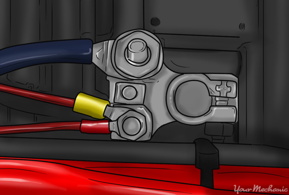
Polarity
In the context of wiring a volt gauge, understanding polarity is crucial for accurate voltage measurements. Polarity refers to the correct orientation of the volt gauge’s terminals relative to the circuit being measured.
When connecting a volt gauge, the positive terminal must be connected to the positive terminal of the circuit, and the negative terminal to the negative terminal. Reversing this polarity will result in incorrect readings or potential damage to the gauge. This is because volt gauges are designed to measure voltage differences, and incorrect polarity can lead to readings that are inverted or offset from the actual voltage.
A real-life example of polarity in wiring a volt gauge is when measuring the voltage of a battery. If the positive terminal of the volt gauge is connected to the negative terminal of the battery, and vice versa, the gauge will display a negative voltage reading. This is because the gauge is interpreting the reversed polarity as a voltage difference in the opposite direction.
Understanding polarity is essential for accurate and safe use of volt gauges in various applications. Incorrect polarity can lead to misleading readings, damage to the gauge, or even electrical hazards. Therefore, it is imperative to pay attention to the polarity of the circuit and the volt gauge during wiring to ensure reliable voltage measurements.
Grounding
Grounding, in the context of wiring a volt gauge, refers to establishing a reference point for voltage measurements. It is crucial for ensuring accurate readings and maintaining safety while using the gauge.
When a volt gauge is properly grounded, it provides a stable reference for voltage measurements. Without proper grounding, the readings can be unreliable or even dangerous. This is because the volt gauge relies on a common ground to measure voltage differences. If the ground reference is not stable or is not connected correctly, the readings will be inaccurate.
A real-life example of proper grounding in wiring a volt gauge is when measuring the voltage of a car battery. The negative terminal of the volt gauge must be connected to the negative terminal of the battery, which is typically grounded to the chassis of the car. This establishes a common ground reference for the voltage measurement, ensuring an accurate reading.
Understanding the importance of proper grounding is essential for accurate and safe use of volt gauges. Neglecting proper grounding can lead to incorrect readings, damage to the gauge, or even electrical hazards. Therefore, it is imperative to pay attention to the grounding of the volt gauge during wiring to ensure reliable voltage measurements.
Calibration
In the realm of electrical measurements, precision is paramount. Volt gauges, devices designed to measure electrical potential difference, are no exception. To guarantee their readings remain accurate over time, regular calibration is essential. This process involves comparing the gauge’s readings against a known voltage source and making necessary adjustments to maintain accuracy.
- Reference Standards: Calibration relies on reference voltage sources of known accuracy. These standards provide a benchmark against which the volt gauge’s readings can be compared and adjusted.
- Environmental Factors: Temperature, humidity, and electromagnetic interference can affect the accuracy of volt gauges. Calibration compensates for these variables, ensuring consistent readings under different operating conditions.
- Component Aging: Over time, the electrical components within a volt gauge can degrade, leading to reduced accuracy. Calibration identifies and corrects for these aging effects.
- Traceability: Regular calibration establishes a traceable history of the volt gauge’s performance, ensuring its measurements can be verified and trusted.
Regular calibration of volt gauges is not merely a recommendation but a crucial step in maintaining the integrity of electrical measurements. By ensuring the gauge’s readings align with known voltage standards, calibration safeguards against erroneous data, faulty diagnoses, and potential safety hazards. It is an indispensable practice for professionals and enthusiasts alike, empowering them with confidence in the accuracy of their electrical measurements.
Display Type
When wiring a volt gauge, selecting the appropriate display type is crucial for the intended application. Analog and digital volt gauges offer distinct advantages and disadvantages, influencing the accuracy, readability, and functionality of the gauge.
Analog volt gauges utilize a moving needle or pointer to indicate voltage levels. They provide a continuous display of voltage fluctuations, making them ideal for monitoring dynamic signals or detecting trends. However, analog gauges may have lower accuracy and precision compared to digital gauges, and they can be affected by external factors such as vibrations or shock.
Digital volt gauges, on the other hand, display voltage readings in numerical form. They offer higher accuracy and resolution, making them suitable for precise measurements and applications where numerical values are critical. Digital gauges are less susceptible to external influences and can often provide additional features such as data logging, peak hold, and programmable ranges.
The choice between analog and digital volt gauges depends on the specific requirements of the application. For applications requiring high accuracy and precise measurements, digital volt gauges are preferred. However, if continuous monitoring of voltage fluctuations is necessary, analog gauges provide a more intuitive and responsive display.
Understanding the characteristics and limitations of different display types is essential for selecting the most suitable volt gauge for a given application. By considering the trade-offs between accuracy, readability, and functionality, users can ensure the volt gauge provides reliable and meaningful voltage measurements.
Range and Resolution
When wiring a volt gauge, careful consideration of its range and resolution is crucial. The range refers to the minimum and maximum voltage values that the gauge can measure, while resolution determines the smallest increment of voltage that it can distinguish. Selecting the appropriate range and resolution ensures accurate and meaningful voltage measurements.
Consider a scenario where a volt gauge with a range of 0-10 volts is used to measure the voltage of a car battery. If the battery voltage is 12.5 volts, the gauge will not be able to provide an accurate reading as it exceeds the gauge’s range. Conversely, if a volt gauge with a range of 0-50 volts is used, it will be able to measure the battery voltage but may not provide sufficient resolution to detect small voltage fluctuations.
Therefore, understanding the intended application and the expected voltage range is essential when wiring a volt gauge. Choosing a gauge with an appropriate range ensures that the measured voltage falls within its measurable limits, preventing inaccurate readings or potential damage to the gauge.
Protection Features
In the context of “Wiring A Volt Gauge”, protection features play a critical role in ensuring the accuracy, longevity, and safety of the gauge. Volt gauges with built-in protection features offer enhanced resilience against electrical hazards and potential damage.
-
Overload Protection:
Overload protection safeguards the volt gauge from damage caused by excessive current flow. A built-in fuse or circuit breaker interrupts the circuit when the current exceeds a predetermined threshold, preventing harm to the gauge and the electrical components it is connected to. -
Reverse Polarity Protection:
Reverse polarity protection prevents damage to the volt gauge and the circuit it is connected to in the event of incorrect polarity connection. Diodes or other protective components ensure that current flows in the intended direction, preventing damage to sensitive electronic components.
Volt gauges with built-in protection features are essential for applications where electrical hazards or incorrect connections may occur. By integrating these protective measures, users can ensure the reliability, accuracy, and safety of their volt gauges in various electrical systems.
Safety Precautions
In the context of “Wiring A Volt Gauge”, adhering to safety precautions is paramount for both the user’s well-being and the integrity of the equipment. Electrical circuits and volt gauges involve the handling of electricity, posing potential hazards if proper safety measures are not followed. Ignoring these precautions can lead to electrical shocks, fires, or damage to the gauge and electrical system.
A crucial safety precaution is ensuring that the circuit being measured is de-energized before connecting the volt gauge. Failure to do so can result in electrical shock or damage to the gauge due to excessive voltage or current. Additionally, using a volt gauge with an appropriate voltage range is essential to prevent damage to the gauge and ensure accurate measurements.
Furthermore, proper insulation and grounding are vital safety measures. Exposed wires or faulty insulation can lead to electrical shock or short circuits. Proper grounding provides a safe path for excess current to flow, protecting against electrical hazards.
Understanding and implementing safety precautions while wiring a volt gauge are essential for ensuring a safe and successful measurement process. Neglecting these precautions can have serious consequences, highlighting their critical importance in the context of “Wiring A Volt Gauge”.


Related Posts


