Wiring A Universal Ignition Switch refers to the process of connecting an aftermarket ignition switch to a vehicle’s electrical system. It involves establishing electrical connections between the switch and essential components like the battery, starter motor, and ignition circuit.
The primary function of an ignition switch is to control the flow of electricity to the vehicle’s ignition system. When the key is turned, it completes the circuit, allowing current to flow to the spark plugs and ignite the engine. Universal ignition switches are designed to be adaptable to various vehicles, offering versatility and ease of installation.
Transitioning to the main article, we will delve deeper into the intricacies of wiring a universal ignition switch. We will examine the necessary tools, safety precautions, and step-by-step instructions to ensure a successful and safe installation.
Wiring a universal ignition switch involves several essential aspects that determine the success and safety of the installation. Understanding these aspects is crucial to ensure the proper functioning of the ignition system and overall vehicle operation.
- Compatibility: Choosing a universal ignition switch compatible with the vehicle’s electrical system and ignition requirements.
- Wiring Diagram: Referencing the vehicle’s wiring diagram to identify the correct wires to connect to the switch.
- Safety Precautions: Disconnecting the battery and taking appropriate measures to prevent electrical hazards.
- Terminal Identification: Accurately identifying the terminals on the switch and matching them to the corresponding wires.
- Crimping and Soldering: Properly crimping and soldering wire connections to ensure secure and reliable electrical connections.
- Insulation: Insulating all connections with heat shrink tubing or electrical tape to prevent short circuits.
- Mounting: Securing the ignition switch in a suitable location that provides easy access and prevents damage.
- Testing: Testing the ignition switch’s functionality before reconnecting the battery to ensure proper operation.
- Troubleshooting: Identifying and resolving any issues that may arise during or after the installation.
- Maintenance: Regular inspection and maintenance of the ignition switch to ensure its continued reliability.
These aspects are interconnected and essential for a successful wiring process. Neglecting any of them can compromise the safety and functionality of the ignition system. By thoroughly considering and addressing each aspect, one can ensure a reliable and efficient ignition switch installation.
Compatibility
When wiring a universal ignition switch, compatibility is paramount. Choosing a switch that is compatible with the vehicle’s electrical system and ignition requirements ensures proper functionality and prevents potential damage.Compatibility encompasses several key facets:
- Electrical Load: The ignition switch must be rated to handle the electrical load of the vehicle’s ignition system. This includes the current draw of the starter motor, ignition coil, and other components.
- Voltage and Grounding: The switch must be compatible with the vehicle’s voltage and grounding system. Most vehicles use a 12-volt electrical system with a negative ground, but some older vehicles may have a 6-volt system or a positive ground.
- Key Type and Configuration: The ignition switch must be compatible with the type of key used by the vehicle. This includes the key blade profile, the number of tumblers, and any security features such as transponder chips.
- Mounting and Dimensions: The ignition switch must be physically compatible with the vehicle’s dashboard or other mounting location. This includes the size, shape, and mounting hardware.
By carefully considering these factors, you can choose a universal ignition switch that is compatible with your vehicle and will provide reliable and safe operation.
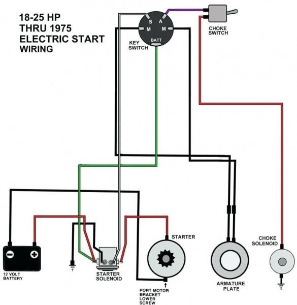
Wiring Diagram
In the context of “Wiring A Universal Ignition Switch,” referencing the vehicle’s wiring diagram is a critical step that directly influences the success and safety of the installation. The wiring diagram provides a detailed schematic representation of the vehicle’s electrical system, including the ignition circuit. It serves as a roadmap, guiding the installer in identifying the correct wires to connect to the universal ignition switch.
Understanding the wiring diagram is essential because aftermarket universal ignition switches are not vehicle-specific. They are designed to be adaptable to various makes and models. Therefore, it is crucial to consult the vehicle’s specific wiring diagram to determine which wires correspond to the ignition switch terminals. Connecting the switch to incorrect wires can lead to electrical faults, damage to components, or even pose safety hazards.
Real-life examples of how referencing the wiring diagram is integral to wiring a universal ignition switch abound. For instance, in a 2005 Honda Civic, the ignition switch has six terminals. Without consulting the wiring diagram, it would be challenging to determine which terminal connects to the battery, starter motor, ignition coil, and accessories. The wiring diagram clearly identifies each wire’s color, gauge, and function, ensuring accurate connections.
The practical significance of understanding the wiring diagram extends beyond simply completing the installation. It empowers the installer to troubleshoot and diagnose ignition-related issues effectively. By tracing the wires from the ignition switch through the wiring diagram, one can identify potential breaks, shorts, or loose connections that may hinder the ignition system’s proper operation.
In summary, referencing the vehicle’s wiring diagram when wiring a universal ignition switch is paramount for several reasons. It ensures the identification of the correct wires for connection, prevents electrical faults and damage, and facilitates troubleshooting. Neglecting this crucial step can compromise the safety and reliability of the ignition system.
Safety Precautions
When dealing with electrical systems, safety should always be the top priority. Wiring a universal ignition switch is no exception. Disconnecting the battery and taking appropriate measures to prevent electrical hazards are essential steps that should never be overlooked.
-
Battery Disconnection:
The first and most important safety precaution is to disconnect the battery. This isolates the ignition switch and other electrical components from the power source, preventing the risk of electrical shocks or short circuits during installation. -
Protective Gear:
Wear appropriate protective gear such as insulated gloves and safety glasses. This minimizes the risk of injury in case of accidental contact with live wires or sparks. -
Hazard Identification:
Identify potential hazards in the work area, such as exposed wires, sharp edges, or flammable materials. Take steps to mitigate these hazards, such as taping exposed wires, covering sharp edges, and keeping flammable materials away from the work area. -
Proper Tools and Equipment:
Use the right tools and equipment for the job. This includes insulated screwdrivers, wire strippers, and a multimeter for testing connections. Using improper tools can increase the risk of accidents or damage to components.
By following these safety precautions, you can significantly reduce the risks associated with wiring a universal ignition switch. Remember, electrical work can be dangerous if proper safety measures are not taken. Always prioritize safety and proceed with caution.
Terminal Identification
In the context of “Wiring A Universal Ignition Switch,” terminal identification plays a critical role in ensuring the proper functioning and safety of the ignition system. It involves correctly identifying the terminals on the ignition switch and matching them to the corresponding wires in the vehicle’s electrical system.
The significance of accurate terminal identification stems from the fact that universal ignition switches are not vehicle-specific. They are designed to be adaptable to various makes and models, each with unique wiring configurations. Without proper identification, there is a high risk of connecting the switch to incorrect wires, which can lead to electrical faults, damage to components, or even pose safety hazards.
Real-life examples of the importance of terminal identification abound. For instance, in a 2007 Chevrolet Silverado, the ignition switch has seven terminals. If the installer fails to identify the correct terminals and connect them to the corresponding wires, it could result in the starter motor engaging continuously, the ignition system not receiving power, or even a short circuit that could damage the vehicle’s electrical system.
The practical significance of understanding terminal identification extends beyond simply completing the installation. It empowers the installer to troubleshoot and diagnose ignition-related issues effectively. By tracing the wires from the ignition switch through the wiring diagram, one can identify potential breaks, shorts, or loose connections that may hinder the ignition system’s proper operation.
In summary, terminal identification is a critical component of “Wiring A Universal Ignition Switch.” It ensures the correct connection of the switch to the vehicle’s electrical system, preventing electrical faults, damage to components, and potential safety hazards. Neglecting this step can compromise the reliability and safety of the ignition system.
Crimping and Soldering
In the context of “Wiring A Universal Ignition Switch,” crimping and soldering wire connections play a crucial role in ensuring the proper functioning and longevity of the ignition system. It involves the use of specialized tools and techniques to create secure and reliable electrical connections between wires and terminals.
-
Proper Crimping:
Crimping involves using a crimping tool to compress a metal sleeve or connector around the stripped ends of two or more wires. This creates a secure mechanical connection that ensures good electrical conductivity. Proper crimping requires using the correct size and type of crimp connector for the wire gauge and application. -
Soldering:
Soldering involves melting a metal alloy with a lower melting point, called solder, onto the crimped connection. This creates a strong, permanent bond between the wires and the terminal. Soldering enhances the electrical conductivity and mechanical strength of the connection, preventing corrosion and ensuring long-term reliability. -
Heat Shrink Tubing:
After soldering, heat shrink tubing is applied over the connection and heated. This shrinks the tubing, creating an insulating layer that protects the connection from moisture, dirt, and other environmental factors. Heat shrink tubing also provides strain relief, preventing the wires from flexing and breaking at the connection point. -
Testing and Inspection:
Once the connections are made, it is essential to test them for continuity and proper functionality. A multimeter can be used to check for continuity, ensuring that current can flow through the connection. Additionally, visual inspection can reveal any loose strands of wire, solder bridges, or other defects that could compromise the connection’s integrity.
By properly crimping, soldering, and insulating wire connections, the installer ensures a secure and reliable ignition system that will provide consistent performance over time. Neglecting these steps can lead to poor electrical connections, intermittent failures, and potential safety hazards.
Insulation
In the context of “Wiring A Universal Ignition Switch,” insulation plays a critical role in ensuring the safety and reliability of the electrical system. It involves covering and protecting electrical connections with materials that prevent current leakage and short circuits.
-
Heat Shrink Tubing:
Heat shrink tubing is a thin-walled, heat-activated material that shrinks when exposed to heat, conforming to the shape of the connection. It provides insulation, strain relief, and protection from environmental factors. -
Electrical Tape:
Electrical tape is a self-adhesive, insulating material that is wrapped around connections to provide insulation and protection. It is commonly used for low-voltage applications and temporary repairs. -
Preventing Short Circuits:
Short circuits occur when current flows through an unintended path, bypassing the intended circuit components. Insulation prevents short circuits by creating a barrier between conductors, ensuring that current flows only through the designated pathways. -
Safety and Reliability:
Proper insulation minimizes the risk of electrical shocks, fires, and damage to components. It ensures the safe and reliable operation of the ignition switch and the entire electrical system.
In summary, insulation is a crucial aspect of “Wiring A Universal Ignition Switch.” By using heat shrink tubing or electrical tape to insulate connections, installers can prevent short circuits, enhance safety, and ensure the long-term reliability of the ignition system.
Mounting
In the context of “Wiring A Universal Ignition Switch,” mounting the ignition switch in a suitable location is a critical component that directly influences the functionality, safety, and longevity of the ignition system. Proper mounting ensures easy access, prevents damage to the switch, and contributes to the overall reliability of the vehicle.
The location of the ignition switch is crucial for both practical and safety reasons. It should be easily accessible to the driver, allowing for quick and convenient starting of the vehicle. At the same time, the location should minimize the risk of accidental activation or damage. This is especially important in vehicles where the ignition switch is located near other controls, such as the gear selector or climate controls.
Real-life examples abound where improper mounting of the ignition switch can lead to problems. For instance, in some older vehicles, the ignition switch was mounted on the steering column. Over time, the constant movement of the steering wheel could cause the switch to loosen, leading to intermittent electrical problems or even a complete failure to start the vehicle. In contrast, modern vehicles typically mount the ignition switch on the dashboard, where it is less prone to damage and easier to access.
The practical applications of understanding the importance of proper mounting extend beyond simply ensuring easy access and preventing damage. It also contributes to the overall safety and reliability of the vehicle. A securely mounted ignition switch minimizes the risk of accidental activation, which can prevent the vehicle from being started unintentionally. Additionally, proper mounting helps protect the switch from environmental factors such as moisture and dust, which can lead to corrosion and premature failure.
In summary, mounting the ignition switch in a suitable location is an essential aspect of “Wiring A Universal Ignition Switch.” It ensures easy access, prevents damage, and contributes to the overall reliability and safety of the ignition system. Neglecting this aspect can lead to a range of problems, from minor inconveniences to potentially dangerous situations.
Testing
In the context of “Wiring A Universal Ignition Switch,” testing the ignition switch’s functionality before reconnecting the battery is a crucial step that should never be overlooked. This ensures that the ignition switch is working properly and that the vehicle will start reliably once the battery is reconnected. There are several key aspects to consider when testing the ignition switch:
-
Electrical Continuity:
Using a multimeter, check for electrical continuity between the ignition switch terminals and the corresponding wires. This ensures that the switch is making proper contact and that current can flow through it. -
Switch Positions:
Test the ignition switch in all of its positions, including “off,” “on,” “start,” and any accessory positions. Make sure that the switch transitions smoothly between positions and that the appropriate circuits are activated or deactivated. -
Starter Motor Engagement:
With the transmission in park or neutral, turn the ignition switch to the “start” position and listen for the starter motor to engage. Make sure that the starter motor cranks the engine over and that the engine starts promptly. -
Security Features:
If the ignition switch has any security features, such as a transponder chip or immobilizer, test these features to ensure that they are functioning properly. This may involve using a special tool or following specific procedures.
By thoroughly testing the ignition switch before reconnecting the battery, you can significantly reduce the risk of problems or malfunctions once the vehicle is started. This simple step can save time, prevent frustration, and ensure the safe and reliable operation of your vehicle.
Troubleshooting
In the context of “Wiring A Universal Ignition Switch,” troubleshooting any issues that may arise during or after the installation is crucial to ensure the proper functioning and reliability of the ignition system. Troubleshooting involves identifying the root cause of a problem and taking appropriate steps to resolve it, ensuring the vehicle operates safely and efficiently.
-
Electrical Connections:
Loose or faulty electrical connections are a common source of issues. Check all connections thoroughly, ensuring they are secure and free of corrosion or damage. Use a multimeter to test for continuity and proper voltage at various points in the circuit. -
Ignition Switch:
The ignition switch itself can also malfunction. Test the switch in all positions, including “off,” “on,” “start,” and any accessory positions. If the switch fails to make proper contact or transition smoothly between positions, it may need to be replaced. -
Starter Motor:
If the engine fails to crank when the ignition switch is turned to the “start” position, the starter motor may be faulty. Check the starter motor’s connections and power supply. Use a multimeter to test for voltage and continuity at the starter motor terminals. -
Security Features:
Some ignition switches have built-in security features, such as transponder chips or immobilizers. If the security system is not functioning properly, it can prevent the vehicle from starting. Check the security system’s components and ensure they are communicating correctly with the ignition switch.
By systematically troubleshooting any issues that arise during or after the installation of a universal ignition switch, you can identify and resolve problems promptly, ensuring the vehicle’s ignition system operates reliably and efficiently. Neglecting troubleshooting can lead to intermittent failures, poor performance, or even safety hazards, making it an essential aspect of “Wiring A Universal Ignition Switch.”
Maintenance
In the context of “Wiring A Universal Ignition Switch,” maintenance and regular inspection are crucial to ensure the continued reliability and longevity of the ignition system. A properly maintained ignition switch minimizes the risk of unexpected failures, reduces downtime, and contributes to the overall safety and performance of the vehicle.
Neglecting maintenance can lead to a range of problems, from minor inconveniences to major safety hazards. For instance, a dirty or corroded ignition switch can cause intermittent starting problems, while a worn or damaged switch can fail completely, leaving the vehicle stranded. Regular inspection and cleaning can help identify potential issues early on, allowing for timely repairs or replacements.
Real-life examples abound where proper maintenance of the ignition switch has prevented costly repairs or dangerous situations. In one instance, a regular inspection revealed a loose connection in the ignition switch wiring. Addressing this issue promptly prevented a potential short circuit that could have caused a fire. In another case, a worn-out ignition switch was replaced before it failed completely, ensuring the vehicle’s reliability during a long road trip.
The practical applications of understanding the importance of maintenance extend beyond simply preventing problems. It also contributes to the vehicle’s overall performance and efficiency. A well-maintained ignition switch ensures a quick and reliable start, minimizing battery drain and reducing emissions. Additionally, regular maintenance can help extend the lifespan of the ignition switch itself, saving money on replacement costs in the long run.
In summary, maintenance and regular inspection of the ignition switch are essential components of “Wiring A Universal Ignition Switch.” By understanding the importance of maintenance, individuals can ensure the continued reliability and safety of their vehicle’s ignition system, preventing costly repairs, minimizing downtime, and contributing to the vehicle’s overall performance and longevity.


Related Posts


