A 50 Amp RV plug diagram provides a visual representation of the electrical connections necessary to safely connect a 50 Amp RV to an external power source. This diagram outlines the proper wiring of the plug’s terminals, ensuring a reliable and secure electrical connection. For instance, a typical 50 Amp RV plug diagram will specify the positioning of the ground, neutral, and hot wires, ensuring proper polarity and preventing electrical hazards.
Understanding and following a 50 Amp RV plug diagram is crucial for preventing electrical damage to the RV and ensuring the safety of passengers. Its benefits include providing a clear and concise guide for correct wiring, reducing the risk of electrical fires, and facilitating efficient and reliable electrical connections. Historically, the development of standardized RV electrical connections, including the 50 Amp plug, has significantly improved the safety and ease of use of RVs.
This article delves into the intricacies of wiring 50 Amp RV plugs, providing detailed instructions, safety precautions, and troubleshooting tips. By exploring these topics, we aim to empower RV owners and enthusiasts with the knowledge and skills necessary for safe and effective electrical connections.
Understanding the essential aspects of wiring a 50 Amp RV plug diagram is crucial for ensuring a safe and reliable electrical connection between your RV and external power sources. These aspects encompass various dimensions, from safety precautions to technical specifications and practical considerations.
- Safety Precautions
- Electrical Wiring
- Plug Configuration
- Grounding
- Polarity
- Voltage and Amperage
- Tools and Equipment
- Troubleshooting
- Code Compliance
- RV Compatibility
Each of these aspects plays a vital role in ensuring a proper electrical connection. For instance, adhering to safety precautions can prevent electrical shocks and fires, while selecting the appropriate plug configuration and wiring ensures compatibility with your RV’s electrical system. Understanding grounding techniques ensures the safe dissipation of electrical currents, and proper polarity prevents damage to electrical appliances. By considering these aspects and following best practices, you can ensure a safe and reliable electrical connection for your RV.
Safety Precautions
In the context of wiring a 50 Amp RV plug diagram, safety precautions play a paramount role in preventing electrical accidents, protecting individuals, and ensuring the longevity of electrical systems. These precautions form an integral aspect of the wiring process, guiding every step from preparation to execution. Without proper safety measures, even a meticulously crafted wiring diagram can pose significant electrical hazards.
A crucial safety precaution when wiring a 50 Amp RV plug is ensuring that all electrical components, including wires, connectors, and the plug itself, are rated for 50 Amp service. Using components with inadequate amperage ratings can lead to overheating, insulation breakdown, and potential electrical fires. Additionally, proper grounding techniques must be followed to provide a safe path for electrical currents to dissipate, minimizing the risk of electrical shocks and equipment damage.
Before commencing any wiring work, it is imperative to verify that the power source is disconnected to prevent accidental energization. This simple step eliminates the risk of electrical shocks and allows for safe handling of electrical components. Moreover, working in a well-ventilated area is essential to avoid exposure to harmful fumes or gases that may be released during soldering or other electrical operations.
By adhering to these safety precautions, individuals can mitigate electrical hazards, ensure the integrity of their RV’s electrical system, and create a safe environment for themselves and others. Neglecting safety precautions can have severe consequences, ranging from minor electrical issues to catastrophic events, highlighting the critical importance of prioritizing safety throughout the wiring process.
Electrical Wiring
Electrical wiring forms the backbone of a 50 Amp RV plug diagram, enabling the safe and efficient flow of electrical current from an external power source into an RV’s electrical system. This intricate network of wires, connectors, and components plays a pivotal role in ensuring that various electrical appliances and systems within the RV function seamlessly.
-
Wire Selection
Choosing the right type and gauge of wire is critical for handling the high amperage of a 50 Amp RV connection. Proper wire selection ensures minimal voltage drop and prevents overheating, safeguarding the electrical system from damage. -
Conductor Material
Copper and aluminum are the two primary conductor materials used in RV electrical wiring. Copper offers superior conductivity and durability, making it the preferred choice for high-amperage applications like 50 Amp RV plugs. -
Connector Types
Electrical connectors provide secure and reliable connections between wires and components. In a 50 Amp RV plug diagram, various connectors are used, including ring terminals, spade terminals, and locking connectors, each designed for specific applications. -
Wiring Techniques
Proper wiring techniques, such as using the correct crimping tools and following color-coding standards, ensure that electrical connections are mechanically sound and electrically safe. These techniques minimize the risk of loose connections, arcing, and potential electrical hazards.
Overall, electrical wiring in the context of a 50 Amp RV plug diagram encompasses a range of components, materials, and techniques that work together to establish a safe and functional electrical connection between an RV and an external power source. Understanding the nuances of each facet of electrical wiring empowers individuals to make informed decisions, troubleshoot potential issues, and maintain a reliable electrical system in their RVs.
Plug Configuration
Plug configuration plays a central role in the accurate and safe wiring of a 50 Amp RV plug diagram. It dictates the specific arrangement and orientation of electrical terminals within the plug, ensuring proper mating with its corresponding receptacle. This precise configuration serves as a critical safety measure, preventing accidental misalignment or improper connections that could lead to electrical hazards.
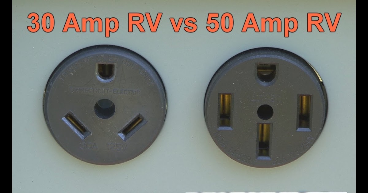
The standard configuration for a 50 Amp RV plug diagram involves four prongs: three flat blades and one round grounding pin. The two larger flat blades carry the hot wires, while the smaller flat blade carries the neutral wire. The round grounding pin provides a low-resistance path for electrical faults, enhancing safety by diverting stray currents away from the RV’s chassis and appliances. This specific arrangement ensures a reliable and secure connection, minimizing the risk of electrical shorts, overheating, and potential damage to the RV’s electrical system.
Understanding plug configuration is crucial for proper wiring and safe operation of 50 Amp RV electrical systems. Incorrect wiring or mismatched plugs can lead to a range of issues, including blown fuses, tripped circuit breakers, and even electrical fires. By adhering to the established configuration, individuals can ensure that their RV’s electrical system functions optimally and safely, preventing costly repairs and potential accidents.
Grounding
Grounding, a fundamental aspect of electrical systems, plays a critical role in Wiring 50 Amp RV Plug Diagrams. It establishes a low-resistance path for electrical faults, providing a safe channel for stray currents to dissipate, thereby preventing damage to electrical equipment and protecting individuals from electrical shocks. Within the context of Wiring 50 Amp RV Plug Diagrams, grounding serves as a critical safety measure, ensuring the proper and secure operation of RV electrical systems.
In a Wiring 50 Amp RV Plug Diagram, grounding is achieved through a dedicated grounding wire, typically identified by its green or bare copper color. This wire connects the RV’s electrical system to the ground rod or grounding bus, providing a direct path for electrical faults to flow into the earth. By diverting these stray currents away from the RV’s chassis and appliances, grounding minimizes the risk of electrical fires, equipment damage, and potential injuries.
Real-life examples of grounding within Wiring 50 Amp RV Plug Diagrams can be observed in the connections between the RV’s electrical panel and the grounding rod, as well as in the grounding of individual electrical appliances and components. These connections ensure that all electrical faults are safely directed away from the RV’s habitable areas, reducing the likelihood of electrical accidents and enhancing the overall safety of the RV’s electrical system.
Understanding the connection between grounding and Wiring 50 Amp RV Plug Diagrams is crucial for ensuring the safe and reliable operation of RV electrical systems. Proper grounding techniques not only protect against electrical hazards but also comply with electrical codes and standards, ensuring the RV’s electrical system meets the required safety criteria. By adhering to these principles, individuals can confidently utilize their RV’s electrical systems, minimizing the risk of electrical accidents and maximizing the safety and enjoyment of their RV experience.
Polarity
Polarity, a fundamental concept in electrical systems, plays a critical role in Wiring 50 Amp RV Plug Diagrams. It refers to the correct alignment of electrical connections, ensuring that current flows in the intended direction, thereby preventing damage to equipment and ensuring safe operation.
In the context of Wiring 50 Amp RV Plug Diagrams, polarity is crucial for establishing a proper connection between the RV’s electrical system and an external power source. Incorrect polarity can lead to a range of issues, including blown fuses, tripped circuit breakers, or even electrical fires. To avoid these hazards, it is essential to adhere to the correct polarity when wiring 50 Amp RV plugs.
Real-life examples of polarity within Wiring 50 Amp RV Plug Diagrams include the orientation of the plug’s blades and terminals. The two larger blades are designed to carry the hot wires, while the smaller blade carries the neutral wire. Additionally, the plug’s round grounding pin provides a low-resistance path for electrical faults, ensuring safety by diverting stray currents away from the RV’s chassis and appliances. Understanding and maintaining proper polarity in these connections is crucial for the safe operation of the RV’s electrical system.
The practical significance of understanding polarity in Wiring 50 Amp RV Plug Diagrams extends beyond preventing electrical hazards. By ensuring proper polarity, individuals can also improve the efficiency and reliability of their RV’s electrical system. Correct polarity minimizes voltage drop and power loss, optimizing the performance of electrical appliances and ensuring a consistent and reliable power supply throughout the RV.
Voltage and Amperage
In the context of Wiring 50 Amp RV Plug Diagrams, voltage and amperage play critical roles in ensuring the safe and efficient operation of RV electrical systems. Voltage, measured in volts (V), represents the electrical potential difference between two points in a circuit, while amperage, measured in amps (A), represents the flow of electrical current. Understanding the relationship between voltage and amperage is essential for proper wiring and maintenance of 50 Amp RV electrical systems.
The voltage and amperage in a Wiring 50 Amp RV Plug Diagram are directly related. Ohm’s Law, a fundamental principle of electricity, states that voltage (V) is equal to current (I) multiplied by resistance (R), or V = I x R. In the context of RV electrical systems, the resistance is relatively constant, meaning that changes in voltage will directly affect the amperage. Higher voltage will result in higher amperage, and vice versa.
Real-life examples of voltage and amperage within Wiring 50 Amp RV Plug Diagrams can be observed in the electrical panels of RVs. These panels typically contain circuit breakers or fuses rated for specific amperages. When the amperage draw on a circuit exceeds the rating of the circuit breaker or fuse, it will trip or blow, respectively, to prevent damage to the electrical system. Understanding the relationship between voltage and amperage allows individuals to properly size and protect electrical components, ensuring the safe and reliable operation of their RV’s electrical system.
The practical applications of understanding voltage and amperage in Wiring 50 Amp RV Plug Diagrams extend beyond ensuring electrical safety. By properly matching voltage and amperage requirements, individuals can optimize the performance and efficiency of their RV’s electrical system. For instance, using the correct voltage and amperage for an air conditioner can ensure it cools effectively while minimizing energy consumption.
Tools and Equipment
In the realm of “Wiring 50 Amp RV Plug Diagrams,” the selection and utilization of appropriate tools and equipment are of paramount importance. These elements form the cornerstone of safe and efficient electrical connections, ensuring the reliable operation of RV electrical systems. Without the necessary tools and equipment, attempting to wire a 50 Amp RV plug diagram can be hazardous and potentially damaging to the RV’s electrical components.
-
Electrical Tester
An electrical tester is an indispensable tool for verifying the presence and flow of electricity. It allows individuals to check for proper voltage and continuity in wires, outlets, and other electrical components. This ensures that the circuit is functioning correctly and safely before connecting it to the RV’s electrical system.
-
Wire Strippers
Wire strippers are specifically designed to remove the outer insulation from electrical wires, exposing the conductive metal beneath. Precise and clean wire stripping is essential for creating secure and reliable electrical connections. Improper stripping can lead to loose connections, arcing, and potential electrical hazards.
-
Crimping Tool
A crimping tool is used to create secure and long-lasting connections between electrical wires and terminals. It applies the appropriate amount of pressure to compress the connector, ensuring a tight and electrically sound connection. Proper crimping techniques minimize the risk of loose connections, which can lead to arcing, overheating, and electrical failures.
-
Electrical Tape
Electrical tape serves the vital purpose of insulating and protecting electrical connections. It is used to wrap and seal exposed wires, terminals, and other electrical components, preventing short circuits and potential electrical hazards. High-quality electrical tape provides excellent insulation, resists moisture, and withstands extreme temperatures, ensuring the longevity and safety of electrical connections.
These tools and equipment represent a foundational aspect of Wiring 50 Amp RV Plug Diagrams. By utilizing the appropriate tools and equipment, individuals can confidently and safely wire their RV’s electrical system, ensuring reliable electrical connections and minimizing the risk of electrical hazards. Neglecting the importance of proper tools and equipment can lead to poorly executed electrical connections, potential damage to RV components, and even electrical fires. Therefore, investing in quality tools and equipment and using them correctly is paramount for the safety and integrity of RV electrical systems.
Troubleshooting
In the realm of “Wiring 50 Amp Rv Plug Diagrams,” troubleshooting plays a critical role in ensuring the safe and reliable operation of RV electrical systems. Troubleshooting involves identifying, diagnosing, and resolving electrical issues that may arise during the wiring process or subsequent use of the RV’s electrical system. Without proper troubleshooting techniques, minor electrical problems can escalate into major hazards, potentially damaging electrical components or even causing electrical fires.
Troubleshooting is an integral component of Wiring 50 Amp RV Plug Diagrams as it enables individuals to identify and rectify electrical faults before they become serious issues. By following systematic troubleshooting procedures, such as checking for loose connections, verifying voltage and continuity, and inspecting components for damage, individuals can isolate and resolve electrical problems efficiently and effectively. Neglecting troubleshooting can lead to persistent electrical issues, diminished performance of RV appliances and systems, and potential safety concerns.
Real-life examples of troubleshooting within Wiring 50 Amp RV Plug Diagrams include resolving issues such as blown fuses, tripped circuit breakers, flickering lights, and malfunctioning appliances. By employing proper troubleshooting techniques, individuals can identify the root cause of these problems, whether it be a loose connection, faulty component, or incorrect wiring. Armed with this knowledge, they can then implement appropriate corrective actions, such as tightening connections, replacing damaged components, or re-wiring affected circuits, to restore the electrical system to proper working order.
The practical applications of understanding troubleshooting in Wiring 50 Amp RV Plug Diagrams extend beyond resolving immediate electrical issues. By developing troubleshooting skills, individuals gain the ability to proactively maintain their RV’s electrical system, identify potential problems before they become major issues, and ensure the long-term reliability and safety of their RV’s electrical components. Troubleshooting empowers individuals to confidently address electrical problems, reducing the need for costly professional repairs and enhancing the overall safety and enjoyment of their RV experience.
Code Compliance
In the realm of “Wiring 50 Amp RV Plug Diagrams,” code compliance plays a pivotal role in ensuring the safety and integrity of RV electrical systems. Electrical codes, established by regulatory bodies, provide a comprehensive set of rules and standards that govern the installation, maintenance, and repair of electrical systems, including those in RVs. Adhering to these codes is not merely a legal obligation but a critical component of responsible RV ownership, safeguarding individuals from electrical hazards and potential accidents.
The connection between code compliance and Wiring 50 Amp RV Plug Diagrams is inseparable. Electrical codes provide specific guidelines for the proper wiring of 50 Amp RV plugs, including the use of appropriate materials, wire gauges, and connectors. These requirements are designed to minimize the risk of electrical fires, shocks, and other hazards that could arise from faulty wiring. For instance, code compliance mandates the use of copper wires with proper insulation and ampacity ratings to handle the high current demands of a 50 Amp RV electrical system.
Real-life examples of code compliance within Wiring 50 Amp RV Plug Diagrams include the requirement for a dedicated grounding wire, the use of locking connectors to prevent accidental disconnections, and the proper sizing of circuit breakers and fuses to protect against overloads. By following these codes, individuals can ensure that their RV’s electrical system meets the minimum safety standards, reducing the likelihood of electrical malfunctions and potential harm.
The practical applications of understanding code compliance in Wiring 50 Amp RV Plug Diagrams extend beyond ensuring safety. Code-compliant electrical systems are more reliable, efficient, and durable. They minimize the risk of power outages, voltage fluctuations, and other electrical problems that can disrupt the comfortable use of RV appliances and systems. By adhering to codes, individuals can enhance the overall performance and lifespan of their RV’s electrical system, maximizing their enjoyment and peace of mind.
RV Compatibility
Within the realm of “Wiring 50 Amp Rv Plug Diagram,” “RV Compatibility” emerges as a critical consideration, influencing the successful installation, operation, and safety of RV electrical systems. It encompasses a range of factors that determine whether a particular 50 Amp RV plug diagram aligns with the electrical characteristics and requirements of a specific RV. Understanding and ensuring RV compatibility is paramount for preventing electrical hazards, optimizing system performance, and maximizing the functionality and enjoyment of RV electrical systems.
-
Electrical Load
The electrical load of an RV, measured in amps, refers to the total amount of current drawn by all electrical devices and appliances operating simultaneously. RV compatibility requires matching the amperage rating of the 50 Amp RV plug diagram to the electrical load of the RV to ensure that the electrical system can safely handle the demand without overloading or tripping circuit breakers.
-
Plug Configuration
The physical configuration of the 50 Amp RV plug, including the number and arrangement of prongs, must be compatible with the RV’s electrical inlet. Mismatched plug configurations can result in improper connections, arcing, and potential electrical fires. Proper alignment and secure connections are essential for safe and efficient power transfer.
-
Voltage Requirements
RVs are designed to operate at a specific voltage, typically 120/240 volts. The 50 Amp RV plug diagram must be compatible with the voltage requirements of the RV to ensure that appliances and systems receive the correct voltage for proper operation. Incorrect voltage can damage electrical components or pose safety hazards.
-
Grounding System
A properly functioning grounding system is crucial for safety in RV electrical systems. The 50 Amp RV plug diagram must incorporate a grounding wire that connects the RV’s electrical system to the ground rod or grounding bus. This provides a safe path for electrical faults to dissipate, preventing shocks and electrical fires.
Ensuring RV compatibility in Wiring 50 Amp Rv Plug Diagrams requires careful consideration of these factors. Mismatched or incorrectly wired components can lead to a range of issues, including blown fuses, tripped circuit breakers, electrical fires, and damage to RV appliances. By understanding and adhering to RV compatibility guidelines, individuals can ensure the safe and reliable operation of their RV’s electrical system.


Related Posts


