A “Wiring 3-Way Switch Diagram” is a detailed schematic illustrating how to connect the wires in a 3-way switch system. In real-world applications, such as a home hallway, a 3-way switch setup allows for light control from two different locations.
Wiring 3-way switches is crucial for convenient lighting control. It offers benefits such as increased safety and user-friendliness. Historically, the development of the 3-way switch in the 1880s played a key role in expanding electrical lighting possibilities.
This article explores the intricacies of wiring 3-way switches, including detailed instructions, safety considerations, and troubleshooting tips. With a focus on clarity and practicality, it aims to equip readers with the knowledge necessary to tackle this electrical task confidently.
Wiring 3-way switches involves essential aspects that contribute to the successful installation and operation of this electrical system. These aspects encompass various dimensions, ranging from safety considerations to practical applications.
- Safety
- Circuit
- Wires
- Connections
- Tools
- Diagram
- Troubleshooting
- Maintenance
- Codes
Understanding these aspects is crucial for ensuring a safe and functional 3-way switch system. The diagram serves as a visual guide, outlining the correct connections and wire configurations. Safety measures, such as proper grounding and circuit protection, are paramount. The choice of appropriate wires and tools ensures durability and efficiency. Proper maintenance practices extend the lifespan of the system, while adherence to electrical codes guarantees compliance with safety standards. Troubleshooting techniques empower users to identify and resolve common issues. By delving into these key aspects, individuals gain a comprehensive understanding of wiring 3-way switches.
Safety
When working with electrical systems, safety should be the utmost priority. Wiring 3-way switches involves handling live electrical components, making it essential to adhere to proper safety measures to prevent electrical shocks, fires, or other hazards. This encompasses various aspects, including:
- Circuit Protection: Circuit breakers or fuses protect electrical circuits from overcurrent conditions that could lead to overheating and fires. Proper circuit protection is crucial to prevent electrical hazards.
- Grounding: Grounding provides a safe path for electrical current to flow in the event of a fault, reducing the risk of shocks or electrocution.
- Proper Wiring: Using the correct wire gauge and ensuring proper connections are essential for safe operation. Loose or damaged connections can cause overheating and pose a fire hazard.
- Insulation: Electrical wires and components should be properly insulated to prevent contact with live electrical parts, minimizing the risk of shocks.
By observing these safety precautions, individuals can minimize the risks associated with wiring 3-way switches and ensure the safe and reliable operation of their electrical systems.
Circuit
In the context of wiring 3-way switches, understanding the concept of a circuit is fundamental. A circuit, in electrical terms, refers to a closed loop that allows electricity to flow. In the case of a 3-way switch system, the circuit consists of the power source, the switches, the light fixture, and the wires connecting these components.
The circuit plays a critical role in the operation of the 3-way switch system. When one of the switches is flipped, it completes the circuit, allowing electricity to flow from the power source, through the switch, to the light fixture, and back to the power source, illuminating the light. Similarly, when the other switch is flipped, it breaks the circuit, interrupting the flow of electricity and turning off the light.
In real-life applications, the circuit is a crucial aspect of wiring 3-way switches. Proper installation and maintenance of the circuit ensure the reliable and safe operation of the 3-way switch system. Understanding the circuit’s components and their connections enables individuals to troubleshoot and resolve any issues that may arise, maintaining the functionality of the lighting system.
In summary, the circuit is an essential aspect of wiring 3-way switches. It provides the pathway for electricity to flow and enables the control of lighting from multiple locations. By grasping the relationship between the circuit and the 3-way switch diagram, individuals can effectively design, install, and maintain these electrical systems, ensuring their optimal performance and safety.
Wires
In the context of wiring 3-way switches, wires play a pivotal role as the conductors of electricity, establishing the connections necessary for the system to function. The type, size, and configuration of wires used in a 3-way switch diagram are critical factors that impact the safe and efficient operation of the lighting system.
The selection of appropriate wires is crucial. Electrical wires are characterized by their gauge, which indicates the thickness of the wire. The thicker the wire, the lower its resistance and the higher its current-carrying capacity. In 3-way switch wiring, the correct wire gauge ensures that the wires can handle the electrical load without overheating or causing a fire hazard.
In real-life applications, wires are the physical components that connect the power source, switches, and light fixture in a 3-way switch system. The diagram serves as a guide for installing the wires in the correct configuration, ensuring that the switches can control the light from different locations. Without proper wiring, the system would not function as intended, and electrical hazards could arise.
Understanding the connection between wires and wiring 3-way switch diagrams empowers individuals to troubleshoot and resolve common issues that may arise. For example, if a light does not turn on when a switch is flipped, it could indicate a loose connection or a faulty wire. By referring to the diagram and inspecting the wires, the problem can be identified and rectified, restoring the functionality of the lighting system.
In summary, wires are an essential component of wiring 3-way switch diagrams, acting as the pathways for electrical current to flow. Proper wire selection, installation, and maintenance are crucial for the safe and effective operation of 3-way switch systems. Understanding the connection between wires and the diagram enables individuals to troubleshoot and resolve issues, ensuring the reliable performance of their electrical systems.
Connections
In the context of “Wiring 3-Way Switch Diagram”, “Connections” encompass the vital links between various components, establishing the physical pathways for electricity to flow and enabling the control of lighting from multiple locations. These connections involve different parts, each playing a specific role in the overall functionality of the system.
- Terminals: The terminals on the switches and light fixture serve as the connection points for the wires. Proper connection at the terminals ensures the flow of electricity through the circuit.
- Wires: Wires act as the conductors, carrying electricity between the power source, switches, and light fixture. The correct wire type and gauge are essential for safe and efficient operation.
- Conduit: In some installations, conduit is used to protect the wires from physical damage and environmental factors, ensuring the reliability and longevity of the connections.
- Junction Box: A junction box provides a central location for connecting multiple wires, creating a junction point in the circuit. Proper connections within the junction box are crucial for maintaining a safe and functional system.
Understanding the connections in a “Wiring 3-Way Switch Diagram” empowers individuals to troubleshoot common issues and perform maintenance tasks. By ensuring proper connections at each point, the system operates reliably, providing convenient lighting control and enhancing the overall safety of the electrical system.
Tools
In the context of “Wiring 3-Way Switch Diagram”, tools play a critical role as facilitators of the wiring process, enabling individuals to establish the necessary electrical connections safely and efficiently. The selection and utilization of appropriate tools directly impact the quality and reliability of the wiring installation.
Among the essential tools for wiring 3-way switches are screwdrivers, pliers, wire strippers, and voltage testers. Screwdrivers are used to tighten and loosen terminal screws, while pliers assist in shaping and bending wires. Wire strippers remove the insulation from wires, exposing the conductive metal beneath. Voltage testers ensure that wires are not live before handling, preventing electrical shocks.
Understanding the cause-and-effect relationship between tools and wiring 3-way switch diagrams empowers individuals to approach electrical tasks with confidence and precision. Proper tool selection and usage minimize the risk of electrical hazards and ensure the safe and effective operation of the lighting system. Furthermore, having the right tools enables DIY enthusiasts and homeowners to tackle electrical projects independently, saving time and resources.
In summary, tools are indispensable components of wiring 3-way switch diagrams, enabling individuals to establish secure electrical connections with accuracy and efficiency. By understanding the importance of tools and utilizing them correctly, one can ensure the reliability and safety of their electrical systems.
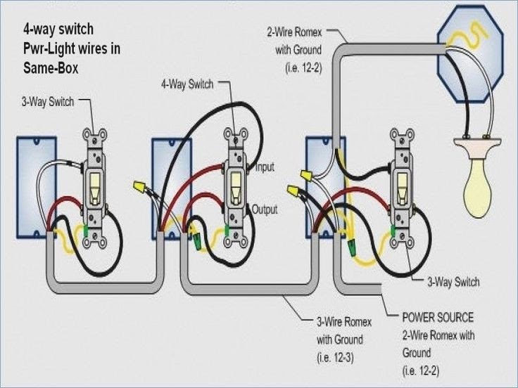
Diagram
In the context of electrical wiring, a diagram serves as the blueprint for establishing connections between electrical components, providing a visual representation of the system’s design and functionality. In the case of “Wiring 3-Way Switch Diagram”, the diagram plays a critical role in guiding the wiring process, ensuring the proper operation of the lighting system.
The cause-and-effect relationship between “Diagram” and “Wiring 3-Way Switch Diagram” is evident in the fact that the diagram acts as a roadmap for the wiring process. Without a clear and accurate diagram, haphazard connections can lead to electrical hazards, malfunctions, and potential damage to equipment or injury to individuals.
Real-life examples of “Diagram” within “Wiring 3-Way Switch Diagram” can be found in residential, commercial, and industrial settings. In homes, wiring diagrams are essential for adding or modifying lighting circuits, ensuring that switches control lights correctly and that proper safety measures are in place.
Understanding the connection between “Diagram” and “Wiring 3-Way Switch Diagram” has practical applications in various scenarios. For electricians, it enables efficient and accurate wiring installations, reducing the risk of errors and ensuring compliance with electrical codes. For homeowners and DIY enthusiasts, it empowers them to tackle electrical projects with confidence, providing a step-by-step guide to wiring 3-way switches.
In summary, the “Diagram” is a critical component of “Wiring 3-Way Switch Diagram”, providing a visual representation of the system’s design and guiding the wiring process effectively. Understanding this connection is essential for safe and efficient electrical installations, empowering individuals to approach electrical tasks with confidence and precision.
Troubleshooting
Within the context of “Wiring 3-Way Switch Diagram”, “Troubleshooting” encompasses a series of diagnostic and corrective actions employed to identify and resolve issues that may arise during the installation or operation of a 3-way switch system. Identifying potential problems and addressing them proactively ensures the safety, reliability, and optimal performance of the lighting system.
-
Electrical Connections
Loose or faulty electrical connections can disrupt the flow of electricity, causing lights to flicker, dim, or fail to turn on. Proper tightening of terminals and secure wire connections are vital to ensure a reliable electrical circuit.
-
Switch Malfunctions
Faulty switches can hinder the proper functioning of a 3-way switch system. Identifying worn-out contacts, loose terminals, or internal switch damage is essential for targeted repairs or switch replacements.
-
Wiring Errors
Incorrect wiring, such as reversed or crossed wires, can lead to unexpected behavior or electrical hazards. Careful tracing and verification of wire connections against the wiring diagram is crucial for rectifying wiring errors.
-
Circuit Overloads
Excessive electrical loads can trip circuit breakers or blow fuses, interrupting power to the 3-way switch system. Identifying the cause of the overload, such as a faulty light fixture or overloaded circuit, is necessary to prevent recurring issues.
Understanding the various facets of “Troubleshooting” empowers individuals to approach electrical issues with greater confidence and problem-solving skills. By systematically identifying and addressing potential problems, they can ensure the safe and reliable operation of their 3-way switch systems, avoiding electrical hazards and maintaining optimal lighting control.
Maintenance
Within the context of “Wiring 3-Way Switch Diagram”, “Maintenance” encompasses the proactive and routine care of the electrical system to ensure its continued reliability, safety, and optimal performance. Regular maintenance practices extend the lifespan of components, prevent potential hazards, and contribute to the overall efficiency of the 3-way switch system.
-
Component Inspection
Periodically inspecting electrical components, such as switches, wires, and terminals, for signs of wear, damage, or loose connections can help identify potential issues before they escalate into more severe problems. Tightening loose connections, replacing worn-out components, and addressing any visible damage contribute to the long-term integrity of the system.
-
Circuit Testing
Using a multimeter or voltage tester to verify the proper functioning of the electrical circuit is an essential maintenance practice. This involves testing for continuity, voltage levels, and ground faults. Early detection of electrical faults allows for prompt corrective actions, reducing the risk of electrical hazards, such as short circuits or fires.
-
Cleaning and Lubrication
Accumulation of dust, dirt, or debris on electrical components can impair their performance and shorten their lifespan. Regular cleaning of switches, terminals, and other components using appropriate cleaning agents helps maintain optimal electrical contact and prevents corrosion. Additionally, lubricating moving parts, such as switch mechanisms, ensures smooth operation and reduces wear.
-
Documentation and Record-Keeping
Maintaining accurate documentation and records of maintenance activities, including dates, observations, and actions taken, is crucial for tracking the system’s maintenance history. This information serves as a valuable reference for future troubleshooting, upgrades, or repairs, allowing for a more informed and efficient approach to maintaining the 3-way switch system.
Regular maintenance practices, encompassing component inspection, circuit testing, cleaning and lubrication, and proper documentation, contribute significantly to the longevity, safety, and reliability of “Wiring 3-Way Switch Diagram” systems. By proactively addressing potential issues and maintaining the integrity of the electrical components, individuals can ensure the optimal performance and peace of mind that comes with a well-maintained electrical system.
Codes
Within the context of “Wiring 3-Way Switch Diagram”, “Codes” encompass a comprehensive set of regulations and guidelines that govern the design, installation, and maintenance of electrical systems, including those involving 3-way switch configurations. These codes are established by recognized authorities, such as the National Electrical Code (NEC) in the United States, to ensure the safety, reliability, and efficiency of electrical installations.
The connection between “Codes” and “Wiring 3-Way Switch Diagram” is critical, as adherence to these codes is paramount for ensuring the safety and proper functioning of the electrical system. Codes provide specific requirements for the selection of electrical components, wire gauges, and installation methods, ensuring that the system meets minimum safety standards and operates as intended. By following the prescribed guidelines, electricians and DIY enthusiasts can minimize the risk of electrical hazards, such as fires, shocks, or equipment damage.
Real-life examples of “Codes” within “Wiring 3-Way Switch Diagram” include specifications for the proper sizing of wires based on the electrical load, the use of approved electrical boxes and fittings, and the requirement for proper grounding and bonding. These code requirements are essential for ensuring that the electrical system can safely handle the electrical demand, preventing overheating and potential electrical faults. Moreover, codes often mandate the use of specific wiring methods, such as conduit or cable trays, to protect wires from physical damage and environmental factors.
Understanding the practical applications of “Codes” in “Wiring 3-Way Switch Diagram” empowers individuals to approach electrical tasks with greater confidence and safety. By adhering to these codes, they can ensure that their electrical installations meet the minimum safety standards, reducing the risk of accidents and costly repairs. Furthermore, compliance with electrical codes often contributes to lower insurance premiums and increased property value, as it demonstrates a commitment to safety and quality workmanship.
In summary, “Codes” play a critical role in “Wiring 3-Way Switch Diagram” by providing essential guidelines for the design, installation, and maintenance of electrical systems. By following these codes, individuals can ensure the safety, reliability, and efficiency of their 3-way switch systems, minimizing the risk of electrical hazards and ensuring compliance with industry standards.


Related Posts


