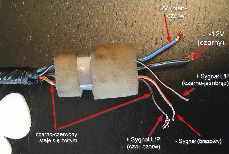
A “Wire Diagram Bose Spare Tire Subwoofer Wiring Diagram” is a visual representation of the electrical connections between the various components of a subwoofer system, specifically designed for integration with a Bose audio system and installed within the spare tire compartment of a vehicle. It illustrates the wiring layout, including the power supply, ground, speaker connections, and any additional control or input/output interfaces.
These diagrams are crucial for ensuring proper installation, functionality, and system optimization. They facilitate troubleshooting, component identification, and maintenance. A notable historical development in this context is the adoption of standardized color-coding schemes for automotive wiring, enhancing the accessibility and ease of comprehension for technicians.
Delving into the technical aspects, this article will delve into the intricacies of Bose spare tire subwoofer wiring diagrams, exploring their components, connection considerations, and the best practices for successful installation and system integration.
Understanding the essential aspects of “Wire Diagram Bose Spare Tire Subwoofer Wiring Diagram” is paramount, as they collectively contribute to the successful installation and integration of a Bose spare tire subwoofer system within a vehicle’s audio configuration. These key aspects encompass:
- Connectivity
- Compatibility
- Functionality
- Accuracy
- Safety
- Optimization
- Troubleshooting
- Customization
Delving deeper into these aspects, we discover their interconnectedness and relevance to the overall topic. For instance, connectivity ensures proper electrical connections between the subwoofer components, while compatibility guarantees seamless integration with the vehicle’s existing audio system. Accuracy in wiring is crucial for optimal sound performance, and safety measures must be adhered to prevent electrical hazards. Optimization techniques can enhance the subwoofer’s output and integration, while troubleshooting capabilities facilitate problem identification and resolution. Finally, customization options allow for tailoring the subwoofer system to specific preferences and vehicle configurations.
Connectivity
Within the context of “Wire Diagram Bose Spare Tire Subwoofer Wiring Diagram,” connectivity plays a pivotal role in establishing proper electrical connections between the subwoofer components and the vehicle’s audio system. The accuracy and reliability of these connections directly impact the functionality and performance of the subwoofer system.
As the wiring diagram outlines the specific wire connections and their respective terminals, it serves as a crucial guide for ensuring proper connectivity. Without accurate connectivity, the subwoofer may not receive power, produce sound, or integrate seamlessly with the vehicle’s audio system. Common connectivity issues include loose or disconnected wires, incorrect wire gauge, and improper grounding, all of which can lead to system malfunctions or degraded sound quality.
In practical applications, understanding connectivity within the wiring diagram enables installers and users to troubleshoot and resolve issues effectively. By referring to the diagram, they can identify and address connectivity problems, ensuring optimal performance and preventing potential electrical hazards. Moreover, the diagram serves as a valuable reference for system modifications or upgrades, allowing for seamless integration of additional components or customization of the subwoofer setup.
In summary, connectivity is a critical aspect of “Wire Diagram Bose Spare Tire Subwoofer Wiring Diagram,” as it directly affects the functionality, performance, and reliability of the subwoofer system. Understanding the principles of connectivity and adhering to the guidelines outlined in the wiring diagram are essential for successful installation, maintenance, and optimization of the subwoofer system.
Compatibility
Within the realm of “Wire Diagram Bose Spare Tire Subwoofer Wiring Diagram,” compatibility assumes paramount importance, dictating the successful integration of the subwoofer system with the vehicle’s existing audio setup and ensuring seamless operation. This aspect encompasses various facets, each of which contributes to the overall compatibility and functionality of the system.
-
Vehicle Compatibility
The wiring diagram must align with the specific make, model, and year of the vehicle to ensure proper fitment and integration with the factory audio system. -
Subwoofer Compatibility
The diagram should be tailored to the specific Bose spare tire subwoofer model, considering its power handling capabilities, impedance, and connection requirements. -
Amplifier Compatibility
If an external amplifier is used, the wiring diagram must account for its compatibility with both the subwoofer and the vehicle’s electrical system. -
Wiring Harness Compatibility
The wiring diagram should specify the type and compatibility of the wiring harness used to connect the subwoofer system to the vehicle’s audio system.
In summary, compatibility within the context of “Wire Diagram Bose Spare Tire Subwoofer Wiring Diagram” encompasses a range of considerations, including vehicle fitment, component specifications, and electrical requirements. By ensuring compatibility across these facets, installers can guarantee a properly functioning and well-integrated subwoofer system that enhances the overall audio experience.
Functionality
Within the context of “Wire Diagram Bose Spare Tire Subwoofer Wiring Diagram,” functionality assumes paramount importance as it dictates the effective operation and performance of the subwoofer system. The wiring diagram serves as a blueprint for establishing proper electrical connections and integrating the subwoofer with the vehicle’s audio system, ultimately ensuring its functionality.
The functionality of the subwoofer system is directly tied to the accuracy and precision of the wiring diagram. A properly designed diagram provides clear instructions on connecting the subwoofer, amplifier (if applicable), and other components, ensuring that each component operates as intended. This includes the correct gauge of wire, pin configuration, and grounding points, all of which contribute to the overall functionality and performance of the system.
Real-life examples abound where precise adherence to the wiring diagram is crucial for optimal functionality. For instance, incorrect wiring can lead to insufficient power delivery to the subwoofer, resulting in weak or distorted sound output. Improper grounding can introduce noise or electrical interference into the audio signal, compromising the listening experience. By following the wiring diagram meticulously, installers can avoid these pitfalls and ensure that the subwoofer system functions at its peak performance.
Understanding the connection between functionality and the wiring diagram empowers installers and users to troubleshoot and resolve issues effectively. By referring to the diagram, they can identify and rectify any discrepancies in the wiring, ensuring that the subwoofer system operates as intended. Moreover, the diagram serves as a valuable reference for system modifications or upgrades, allowing for seamless integration of additional components or customization of the subwoofer setup.
In summary, functionality is inextricably linked to “Wire Diagram Bose Spare Tire Subwoofer Wiring Diagram.” By adhering to the guidelines outlined in the diagram, installers and users can ensure that the subwoofer system is properly connected, integrated, and operating at its optimal level, delivering an enhanced and immersive audio experience.
Accuracy
Within the context of “Wire Diagram Bose Spare Tire Subwoofer Wiring Diagram,” accuracy takes center stage, playing a pivotal role in ensuring the subwoofer system’s optimal performance and seamless integration with the vehicle’s audio system. Accuracy in this context encompasses multiple facets, each of which contributes to the overall functionality and reliability of the subwoofer setup.
-
Precise Connections
The wiring diagram must accurately specify the connection points for the subwoofer, amplifier, and other components, ensuring that each component is properly connected and operating as intended. Incorrect wiring can lead to malfunctions, degraded sound quality, or even electrical hazards.
-
Color-Coding Compliance
Automotive wiring often follows standardized color-coding schemes. The wiring diagram must adhere to these color codes to facilitate easy identification and prevent confusion during installation. Non-standard or inaccurate color-coding can lead to misconnections and subsequent system failures.
-
Gauge and Material Specifications
The wiring diagram should specify the appropriate wire gauge and material for each connection. Using incorrect wire gauge or materials can compromise the system’s performance and reliability, leading to power loss, signal degradation, or overheating issues.
-
Grounding Points
Proper grounding is crucial for the subwoofer system’s safety and performance. The wiring diagram must accurately indicate the designated grounding points to ensure a reliable electrical connection to the vehicle’s chassis. Incorrect grounding can result in electrical noise, interference, or even damage to the subwoofer or other components.
In summary, accuracy in “Wire Diagram Bose Spare Tire Subwoofer Wiring Diagram” is paramount for achieving a well-functioning and reliable subwoofer system. By adhering to the precise specifications and guidelines outlined in the diagram, installers can ensure that the subwoofer is properly connected, integrated, and operating at its optimal level, delivering an enhanced and immersive audio experience.
Safety
Within the context of “Wire Diagram Bose Spare Tire Subwoofer Wiring Diagram,” safety takes paramount importance, ensuring the protection of both the audio system and the vehicle itself from electrical hazards and potential damage. This aspect encompasses various facets, each of which plays a crucial role in maintaining a safe and reliable subwoofer installation.
-
Electrical Insulation
Electrical insulation safeguards against electrical shocks and short circuits by preventing unintended contact between wires and other components. The wiring diagram should specify proper insulation materials and techniques to ensure that all electrical connections are adequately insulated.
-
Grounding
Proper grounding provides a safe path for electrical current to flow, preventing voltage spikes and electrical noise. The wiring diagram must accurately indicate the designated grounding points to ensure a reliable electrical connection to the vehicle’s chassis. Incorrect grounding can lead to electrical hazards and interference with other electronic systems.
-
Fuse Protection
Fuses act as safety devices, protecting the subwoofer system and the vehicle’s electrical system from overcurrent conditions. The wiring diagram should specify the appropriate fuse ratings for each component, ensuring that the system is adequately protected from electrical faults.
-
Wire Gauge and Material
Using the correct wire gauge and material is essential for safety. Insufficient wire gauge can lead to overheating and potential fire hazards, while inappropriate wire material can result in corrosion or signal degradation. The wiring diagram should specify the appropriate wire specifications to ensure a safe and reliable installation.
By adhering to the safety guidelines outlined in the wiring diagram, installers can ensure that the subwoofer system is installed and integrated safely, minimizing the risk of electrical hazards and protecting both the audio system and the vehicle from potential damage. Safe practices, proper insulation, and appropriate component selection are paramount for a reliable and enjoyable audio experience.
Optimization
Optimization plays a pivotal role in “Wire Diagram Bose Spare Tire Subwoofer Wiring Diagram” as it allows for fine-tuning the subwoofer system’s performance to achieve the desired sound quality and integration with the vehicle’s audio setup. By optimizing the system, installers can maximize its potential and ensure a seamless and immersive audio experience.
The wiring diagram provides a foundation for optimization by outlining the electrical connections and component interactions. However, achieving optimal performance requires careful consideration of several factors, including:
- Power Delivery: Optimizing the power supply to the subwoofer ensures it receives sufficient power to operate at its full potential. This involves selecting the appropriate wire gauge and routing the power cables efficiently to minimize voltage drop.
- Signal Quality: Maintaining the integrity of the audio signal is crucial for achieving high-quality sound output. Optimization involves using high-quality speaker cables and minimizing signal interference by proper grounding and noise isolation techniques.
- Subwoofer Placement: Strategic placement of the subwoofer within the spare tire compartment can significantly impact its performance. Optimization involves considering factors such as the subwoofer’s size, shape, and orientation to achieve optimal sound dispersion and minimize resonance.
- System Tuning: Fine-tuning the subwoofer’s crossover settings, equalization, and gain levels is essential for achieving a balanced and cohesive sound integration with the vehicle’s audio system.
By following the guidelines and applying optimization techniques outlined in the wiring diagram, installers can unlock the full potential of the Bose spare tire subwoofer system. This understanding empowers them to customize the subwoofer’s performance, tailor it to their specific preferences, and achieve an enhanced audio experience.
Troubleshooting
Troubleshooting plays a pivotal role in the context of “Wire Diagram Bose Spare Tire Subwoofer Wiring Diagram” as it empowers users and installers to identify and resolve issues that may arise during the installation and operation of the subwoofer system. The wiring diagram serves as a crucial foundation for troubleshooting, providing a visual representation of the electrical connections and component interactions within the system.
Understanding the relationship between troubleshooting and the wiring diagram is essential for effective problem-solving. The wiring diagram provides a systematic approach to tracing electrical connections, identifying potential points of failure, and isolating the source of issues. By analyzing the diagram, installers can methodically check each connection, ensuring proper wire gauge, secure connections, and correct polarity. This structured approach facilitates the identification of loose wires, faulty components, or incorrect grounding, enabling efficient troubleshooting and timely resolution of problems.
Real-life examples abound where troubleshooting in conjunction with the wiring diagram proves invaluable. For instance, if the subwoofer produces no sound, the wiring diagram guides the installer in checking the power supply, ground connections, and speaker wire integrity. By systematically following the diagram, the installer can quickly identify a blown fuse, a loose ground wire, or a damaged speaker cable, allowing for prompt repair or replacement.
The practical applications of troubleshooting within the context of “Wire Diagram Bose Spare Tire Subwoofer Wiring Diagram” extend beyond resolving immediate issues. By understanding the system’s electrical connections and potential failure points, installers and users can proactively prevent problems from occurring. Regular inspections and maintenance, guided by the wiring diagram, can identify loose connections, aging wires, or potential corrosion, enabling timely intervention and ensuring the subwoofer system’s longevity and optimal performance.
In summary, troubleshooting is inextricably linked to “Wire Diagram Bose Spare Tire Subwoofer Wiring Diagram,” providing a systematic and effective approach to problem-solving and system maintenance. By leveraging the wiring diagram as a troubleshooting tool, installers and users can quickly identify and resolve issues, ensuring the subwoofer system operates at its peak performance, delivering an immersive and enjoyable audio experience.
Customization
Within the context of “Wire Diagram Bose Spare Tire Subwoofer Wiring Diagram,” customization holds immense significance as it empowers users to tailor the subwoofer system to their specific preferences and vehicle configurations, unlocking a truly personalized audio experience. The wiring diagram serves as a foundational blueprint, providing a framework for customization while ensuring the system’s integrity and functionality.
The relationship between customization and the wiring diagram is bidirectional. On the one hand, the wiring diagram outlines the electrical connections and component interactions, providing a solid foundation for customization. On the other hand, customization often necessitates modifications to the wiring, requiring a thorough understanding of the diagram to ensure proper implementation. This interplay between customization and the wiring diagram empowers users to explore various options and fine-tune the subwoofer system to their desired specifications.
Real-life examples abound where customization within the context of “Wire Diagram Bose Spare Tire Subwoofer Wiring Diagram” has yielded remarkable results. For instance, enthusiasts may opt to upgrade the subwoofer enclosure to enhance sound quality and aesthetics. The wiring diagram guides them in modifying the power and signal connections accordingly, ensuring seamless integration with the existing audio setup. Additionally, users may choose to add an external amplifier to boost the subwoofer’s output power. The wiring diagram provides clear instructions on how to connect the amplifier, ensuring proper power distribution and signal flow.
The practical applications of understanding the connection between customization and the wiring diagram extend beyond individual preferences. Car audio competitions often involve heavily customized subwoofer systems, pushing the boundaries of audio performance. By leveraging their understanding of the wiring diagram, competitors can fine-tune every aspect of the system, from power delivery to sound reproduction, to achieve award-winning results. Moreover, this understanding empowers professional installers to cater to the diverse needs of their clients, tailoring subwoofer systems to specific vehicle models and audio preferences.
In summary, customization is inextricably linked to “Wire Diagram Bose Spare Tire Subwoofer Wiring Diagram,” providing a pathway for users to personalize their audio experience and achieve optimal system performance. The wiring diagram serves as a crucial guide, enabling informed modifications and ensuring the system’s integrity. Understanding this connection empowers enthusiasts, installers, and competitors alike to unlock the full potential of their subwoofer systems, delivering immersive and tailored audio experiences.


Related Posts


