A Warn Winch A2000 Wiring Diagram outlines the electrical connections and components of a Warn A2000 winch system. It is an essential guide for installing and maintaining the winch, ensuring proper functionality and safety.
This diagram plays a crucial role in tasks such as troubleshooting electrical issues, identifying faulty components, and ensuring compliance with electrical codes. It empowers users to perform maintenance and repairs without the need for extensive electrical knowledge. The diagram’s relevance extends to various applications, including automotive, off-roading, and industrial settings where winches are commonly used.
This wiring diagram is a valuable asset, contributing to the safe and efficient operation of Warn A2000 winches. Its historical importance lies in the evolution of winch technology, where standardized wiring diagrams have become an industry norm, facilitating maintenance and ensuring safety across a wide range of users and applications.
Delving into the essential aspects of “Warn Winch A2000 Wiring Diagram” is crucial to comprehend its significance and implications. As a “noun,” it represents a tangible document that serves as a guide for electrical connections and components within a Warn A2000 winch system. Understanding these key aspects empowers users to install, maintain, and troubleshoot the winch effectively, ensuring optimal performance and safety.
- Accuracy: The diagram provides precise information on electrical connections, ensuring proper functionality and preventing electrical hazards.
- Comprehensiveness: It encompasses all essential electrical components and their interconnections, offering a complete overview of the winch’s electrical system.
- Clarity: The diagram is designed to be easy to understand, with clear symbols and annotations, facilitating interpretation and reducing errors.
- Safety: By adhering to the diagram’s instructions, users can ensure safe electrical connections, minimizing the risk of electrical shocks or fires.
- Troubleshooting: The diagram aids in identifying and resolving electrical issues, enabling users to diagnose and repair problems efficiently.
- Compliance: It aligns with industry standards and electrical codes, ensuring compliance with safety regulations and best practices.
- Versatility: The diagram is applicable to various models and configurations of Warn A2000 winches, providing a universal guide for electrical connections.
- Availability: It is readily accessible, typically included with the winch or available online, making it convenient for users to access and utilize.
These key aspects collectively contribute to the significance of the Warn Winch A2000 Wiring Diagram. Its accuracy, comprehensiveness, and clarity ensure the safe and efficient installation, maintenance, and troubleshooting of the winch’s electrical system. By adhering to the diagram’s instructions, users can prevent electrical hazards, diagnose and resolve issues promptly, and maintain the winch’s optimal performance.
Accuracy
Within the context of “Warn Winch A2000 Wiring Diagram,” accuracy assumes paramount importance. Precise information on electrical connections is crucial for proper winch functionality and the prevention of electrical hazards. This accuracy manifests itself in various facets:
- Component Identification: The diagram accurately identifies each electrical component, ensuring proper connections and eliminating confusion. This precision is vital to prevent misconnections that could lead to malfunctions or safety risks.
- Wire Specifications: The diagram specifies the correct wire gauge and type for each connection, ensuring optimal current flow and preventing overheating. Accurate wire specifications contribute to the winch’s efficiency and longevity.
- Connection Points: The diagram precisely indicates the connection points for each component, guiding users to establish secure and reliable electrical connections. Accurate connection points minimize the risk of loose or intermittent connections that could disrupt winch operation.
- Polarity: The diagram accurately depicts the polarity of electrical connections, ensuring proper current flow and preventing damage to components. Correct polarity is crucial for the winch’s safe and efficient operation.
Overall, the accuracy of the Warn Winch A2000 Wiring Diagram ensures that users can establish precise electrical connections, preventing malfunctions, electrical hazards, and potential damage to the winch system. This accuracy is a cornerstone of the diagram’s value, empowering users to install, maintain, and troubleshoot the winch’s electrical system with confidence.
Comprehensiveness
Within the realm of “Warn Winch A2000 Wiring Diagram,” comprehensiveness emerges as a defining characteristic, ensuring that the diagram provides a thorough and complete overview of the winch’s electrical system. This all-encompassing approach manifests itself in several key facets:
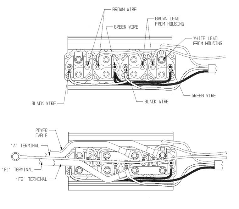
- Essential Components: The diagram encompasses all indispensable electrical components within the winch system, including the motor, solenoid, contactor, and control switches. By incorporating every crucial component, it empowers users to gain a holistic understanding of the system’s electrical architecture.
- Interconnections: Beyond individual components, the diagram meticulously illustrates the interconnections between them, showcasing the flow of electrical current throughout the system. This detailed representation enables users to trace the path of electricity, identify potential connection issues, and troubleshoot problems effectively.
- Wiring Details: The diagram extends its comprehensiveness to include specific wiring details, such as wire gauge, color coding, and terminal connections. This granular level of information guides users in selecting the appropriate wiring materials, ensuring secure connections, and facilitating efficient current flow.
- System Overview: Collectively, the inclusion of essential components, interconnections, and wiring details provides a comprehensive overview of the winch’s electrical system. This holistic perspective empowers users to visualize the system’s operation, anticipate potential issues, and perform maintenance and repairs with confidence.
In essence, the comprehensiveness of the Warn Winch A2000 Wiring Diagram serves as a valuable asset for users, enabling them to thoroughly understand the electrical system, troubleshoot issues with precision, and maintain the winch’s optimal performance. It is a testament to the meticulous attention to detail and commitment to user empowerment that characterizes this essential document.
Clarity
Within the context of “Warn Winch A2000 Wiring Diagram,” clarity emerges as a paramount aspect, empowering users to effortlessly comprehend the intricate electrical system of their winch. This clarity manifests itself in a multitude of ways, each contributing to the overall effectiveness and accessibility of the diagram.
- Intuitive Symbols: The diagram employs a standardized set of symbols that are universally recognized in the electrical industry. These symbols convey the function and purpose of each component, eliminating confusion and simplifying interpretation.
- Color Coding: Color coding is strategically employed to differentiate between different types of wires and connections. This visual cue enhances clarity, enabling users to quickly identify and trace the flow of electricity throughout the system.
- Detailed Annotations: Accompanying the symbols and color coding are detailed annotations that provide additional information and guidance. These annotations clarify the purpose of each connection, the function of each component, and any special considerations or.
- Logical Layout: The diagram is meticulously organized in a logical and intuitive manner. This layout facilitates easy navigation, allowing users to quickly locate the information they need without getting lost in a maze of lines and symbols.
The collective impact of these clarity-enhancing elements is a diagram that is accessible and understandable even to those without extensive electrical knowledge. This clarity is essential for ensuring accurate installation, efficient maintenance, and effective troubleshooting of the Warn Winch A2000 electrical system, empowering users to operate their winches with confidence and peace of mind.
Safety
Within the realm of “Warn Winch A2000 Wiring Diagram,” safety stands as a paramount concern, inextricably linked to the diagram’s meticulous instructions. By adhering to these guidelines, users can establish secure and reliable electrical connections, effectively minimizing the risk of electrical shocks or fires.
Electrical hazards pose a significant threat in the context of winch operation. Improper wiring can lead to loose connections, short circuits, and overheating, potentially resulting in catastrophic consequences. The Warn Winch A2000 Wiring Diagram serves as a vital tool in mitigating these risks by providing clear instructions for safe electrical connections.
For instance, the diagram specifies the appropriate wire gauge for each connection, ensuring that the wires can safely carry the required current. It also indicates the proper polarity for connections, preventing incorrect wiring that could damage components or create electrical hazards.
Furthermore, the diagram’s comprehensive nature ensures that users can visualize the entire electrical system, identify potential trouble spots, and take proactive measures to prevent accidents. By empowering users with this knowledge, the diagram contributes significantly to the safe operation of Warn A2000 winches.
In summary, the “Safety: By adhering to the diagram’s instructions, users can ensure safe electrical connections, minimizing the risk of electrical shocks or fires.” aspect of the Warn Winch A2000 Wiring Diagram is of paramount importance. By following the diagram’s guidelines, users can create a safe and reliable electrical system for their winch, minimizing the risk of electrical hazards and ensuring the winch’s optimal performance.
Troubleshooting
Within the context of “Warn Winch A2000 Wiring Diagram,” troubleshooting emerges as a critical component, empowering users to identify and resolve electrical issues, ultimately ensuring the winch’s optimal performance and longevity.
The diagram’s comprehensive nature provides a solid foundation for effective troubleshooting. By visually representing the entire electrical system, it allows users to trace the flow of electricity and identify potential trouble spots. This comprehensive view enables users to pinpoint the source of electrical problems quickly and accurately.
Furthermore, the diagram’s clear instructions and detailed annotations guide users through the troubleshooting process. It provides step-by-step guidance on testing connections, identifying faulty components, and implementing appropriate repair measures. This structured approach simplifies troubleshooting, even for users with limited electrical experience.
Real-life examples further illustrate the practical significance of troubleshooting within the Warn Winch A2000 Wiring Diagram. For instance, if the winch fails to operate, users can refer to the diagram to check the continuity of the power supply, test the solenoid, and inspect the motor connections. By following the diagram’s troubleshooting guide, users can efficiently diagnose the root cause of the problem and implement the necessary repairs.
In summary, the “Troubleshooting: The diagram aids in identifying and resolving electrical issues, enabling users to diagnose and repair problems efficiently.” aspect of the Warn Winch A2000 Wiring Diagram is crucial for maintaining a well-functioning winch system. By empowering users to troubleshoot and resolve electrical problems effectively, the diagram contributes to the winch’s reliability, safety, and overall performance.
Compliance
Within the context of “Warn Winch A2000 Wiring Diagram,” compliance assumes paramount importance, ensuring adherence to established industry standards and electrical codes. This compliance manifests itself in several key facets, each contributing to the safe and efficient operation of the winch system.
- Conformance to UL Standards: The diagram aligns with Underwriters Laboratories (UL) standards, a globally recognized benchmark for electrical safety. By meeting UL requirements, the diagram ensures that the winch’s electrical system meets rigorous safety criteria, minimizing the risk of electrical hazards.
- Compliance with NEC Regulations: The diagram complies with the National Electrical Code (NEC), a comprehensive set of regulations governing electrical installations in the United States. Adherence to NEC standards ensures that the winch’s electrical system meets local safety codes and best practices, safeguarding users and property.
- Compatibility with Local Codes: The diagram considers local electrical codes and regulations, ensuring that the winch’s electrical system is compatible with the specific requirements of the region where it is installed. This compliance ensures that the winch meets local safety standards and avoids potential conflicts with local authorities.
- Manufacturer’s Specifications: The diagram aligns with the electrical specifications outlined by Warn Industries, the manufacturer of the A2000 winch. By adhering to manufacturer’s guidelines, the diagram ensures that the winch’s electrical system operates within its intended parameters, maximizing performance and longevity.
Collectively, these facets of compliance contribute to the safety and reliability of the Warn Winch A2000 Wiring Diagram. By conforming to industry standards, electrical codes, and manufacturer’s specifications, the diagram empowers users to create a compliant winch electrical system that meets regulatory requirements, minimizes safety risks, and ensures optimal performance.
Versatility
Within the realm of “Warn Winch A2000 Wiring Diagram,” versatility emerges as a defining characteristic, enabling the diagram to transcend specific models and configurations of Warn A2000 winches. This adaptability manifests itself in several key facets, each contributing to the diagram’s universal appeal and effectiveness.
- Model Compatibility: The diagram encompasses the electrical connection requirements of various Warn A2000 winch models, ensuring its applicability across a wide range of winch configurations.
- Mounting Variations: The diagram caters to different winch mounting variations, whether it’s a front-mount, rear-mount, or portable winch setup, providing a comprehensive guide for each scenario.
- Accessory Integration: The diagram incorporates the electrical connections for commonly used accessories, such as remote controls, solenoids, and contactors, allowing users to seamlessly integrate these components into their winch system.
- Wiring Options: The diagram provides guidance on various wiring options, including wire gauge, length, and routing, empowering users to customize the electrical installation based on their specific needs and vehicle configuration.
Collectively, these facets of versatility render the Warn Winch A2000 Wiring Diagram a truly universal guide for electrical connections. Its adaptability to different models, configurations, and accessory integrations empowers users to confidently install and maintain their Warn A2000 winches, maximizing performance and ensuring reliable operation in diverse applications.
Availability
The availability of the “Warn Winch A2000 Wiring Diagram” is a crucial factor that enhances its value and usability. Its accessibility through multiple channels ensures that users can easily obtain the diagram, regardless of their location or circumstances. This ready availability has a direct impact on the effectiveness and practicality of the diagram.
Firstly, including the diagram with the winch upon purchase eliminates the need for users to search for it separately. This convenience factor is particularly beneficial for first-time winch users who may not be familiar with the installation process. Having the diagram readily available allows them to proceed with the installation without delay or the hassle of searching for the correct diagram online.
Secondly, the online availability of the diagram provides an additional layer of accessibility. Users who have misplaced or lost their physical copy can easily download a new one from the Warn website or other reputable online sources. This ensures that they always have access to the most up-to-date version of the diagram, which may include modifications or improvements.
In summary, the availability of the “Warn Winch A2000 Wiring Diagram” is a key aspect that contributes to its overall effectiveness. Its inclusion with the winch and its online accessibility empower users to easily access the diagram, ensuring a smooth and successful winch installation and maintenance process.


Related Posts


