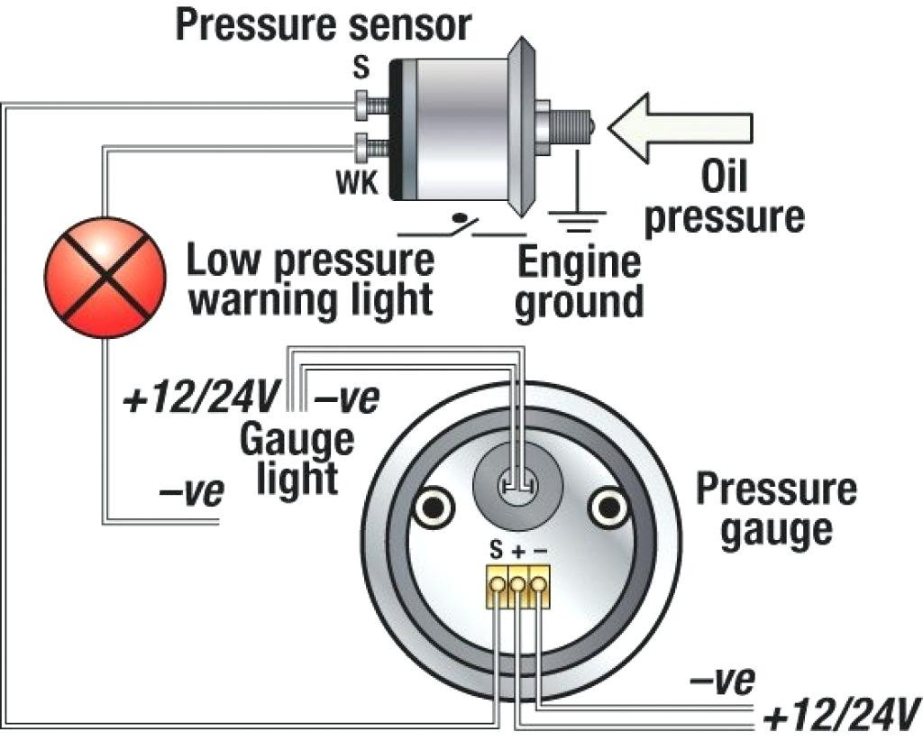
A VDO oil pressure gauge wiring diagram outlines the proper electrical connections between the gauge, the oil pressure sensor, and the vehicle’s power source. It helps ensure accurate readings and prevents incorrect gauge operation or damage to the gauge or vehicle components.
An oil pressure gauge is a crucial component in engine monitoring systems. It measures the oil pressure in the engine, providing information on the engine’s lubrication system’s health. The wiring diagram ensures the proper functioning of the gauge and prevents electrical issues that can lead to unreliable readings or gauge failure.
This article will delve into the details of VDO oil pressure gauge wiring diagrams, discussing the different types of wiring diagrams, the importance of following them correctly, and the consequences of incorrect wiring.
VDO oil pressure gauge wiring diagrams play a crucial role in ensuring accurate oil pressure readings and the proper functioning of the engine lubrication system. Understanding the key aspects of these wiring diagrams is essential for correct installation, maintenance, and troubleshooting.
- Wiring Configuration: Outlines the specific wire connections between the gauge, oil pressure sensor, and power source.
- Voltage Requirements: Specifies the voltage range required for the gauge to operate correctly.
- Grounding: Ensures a proper electrical path for the gauge to function.
- Sensor Compatibility: Indicates the type of oil pressure sensor compatible with the gauge.
- Gauge Calibration: Provides instructions for calibrating the gauge to ensure accurate readings.
- Wire Gauge: Specifies the appropriate wire thickness for the electrical connections.
- Connector Types: Outlines the types of connectors used for the wiring harness.
- Diagram Interpretation: Guides on how to read and interpret the wiring diagram.
- Troubleshooting: Provides assistance in diagnosing and resolving electrical issues related to the gauge.
These aspects are interconnected and crucial for the effective operation of the oil pressure gauge. Incorrect wiring can lead to inaccurate readings, gauge damage, or even engine damage due to improper lubrication. Therefore, it is essential to follow the wiring diagram carefully during installation and maintenance.
Wiring Configuration
The wiring configuration section of a VDO oil pressure gauge wiring diagram is critical for establishing proper electrical connections between the gauge, the oil pressure sensor, and the power source. It provides a detailed layout of the wire connections, including the wire colors, terminal assignments, and connection points.
Understanding the wiring configuration is essential for the accurate functioning of the oil pressure gauge. Incorrect wiring can lead to incorrect readings, gauge damage, or even engine damage due to improper lubrication. Therefore, it is important to follow the wiring configuration carefully during installation and maintenance.
A real-life example of the importance of wiring configuration can be seen in the installation of an oil pressure gauge in a vehicle. If the wiring is not configured correctly, the gauge may not receive the correct voltage or ground, resulting in inaccurate readings or complete failure. This could lead to the driver being unaware of a potential engine problem, such as low oil pressure, which could result in engine damage.
In conclusion, the wiring configuration section of a VDO oil pressure gauge wiring diagram is a crucial component for ensuring the accurate and reliable operation of the gauge. Understanding the wiring configuration and following it precisely is essential for proper installation, maintenance, and troubleshooting.
Voltage Requirements
Voltage requirements are a fundamental aspect of VDO oil pressure gauge wiring diagrams. Understanding the voltage specifications is crucial for ensuring the gauge’s proper operation and preventing damage.
- Power Source Compatibility: The wiring diagram specifies the voltage range compatible with the power source, typically 12V or 24V. Matching the gauge’s voltage requirements to the power source ensures accurate readings and prevents electrical issues.
- Gauge Operating Range: The diagram outlines the voltage range within which the gauge operates correctly. Operating outside this range can lead to inaccurate readings or gauge failure.
- Voltage Regulator: In some cases, a voltage regulator may be required to stabilize the voltage supplied to the gauge, especially when using power sources with fluctuating voltages.
- Electrical Interference: Incorrect voltage can cause electrical interference, affecting the gauge’s accuracy and potentially damaging other electronic components in the vehicle.
Understanding voltage requirements ensures a reliable and accurate oil pressure gauge reading. Ignoring these specifications can result in incorrect readings, gauge damage, or electrical issues. Therefore, it is essential to consult the wiring diagram and follow the voltage requirements precisely during installation and maintenance.
Grounding
In the context of VDO oil pressure gauge wiring diagrams, grounding plays a critical role in establishing a complete electrical circuit and ensuring the gauge’s proper operation. Without proper grounding, the gauge may not function correctly or may provide inaccurate readings.
The purpose of grounding is to provide a low-resistance path for electrical current to flow back to the power source, completing the circuit. In a VDO oil pressure gauge wiring diagram, the ground connection is typically made to the vehicle’s chassis or a dedicated ground terminal.
A real-life example of the importance of grounding in a VDO oil pressure gauge wiring diagram is the connection between the gauge and the oil pressure sensor. The sensor requires a good ground connection to accurately measure and transmit the oil pressure readings to the gauge. If the ground connection is loose or faulty, the sensor may not function correctly, resulting in inaccurate or intermittent oil pressure readings.
Understanding the critical role of grounding in VDO oil pressure gauge wiring diagrams is essential for proper installation and maintenance. A secure and reliable ground connection ensures accurate gauge readings, prevents electrical issues, and contributes to the overall reliability of the vehicle’s engine monitoring system.
Sensor Compatibility
Sensor compatibility is a critical component of VDO oil pressure gauge wiring diagrams. The type of oil pressure sensor used must be compatible with the gauge to ensure accurate readings and proper functionality.
The sensor compatibility section of the wiring diagram specifies the type of sensor required, such as a resistive or variable reluctance sensor. The sensor must be able to provide a signal that is compatible with the gauge’s input range. Using an incompatible sensor can result in inaccurate readings or gauge failure.
A real-life example of sensor compatibility in a VDO oil pressure gauge wiring diagram is the use of a resistive sensor with a gauge designed for a variable reluctance sensor. In this case, the gauge will not be able to interpret the signal from the sensor correctly, leading to incorrect oil pressure readings.
Understanding the importance of sensor compatibility in VDO oil pressure gauge wiring diagrams is crucial for proper installation and maintenance. Using the correct sensor ensures accurate gauge readings, prevents electrical issues, and contributes to the overall reliability of the vehicle’s engine monitoring system.
Gauge Calibration
Gauge calibration is a crucial aspect of VDO oil pressure gauge wiring diagrams. It ensures the gauge provides accurate and reliable readings, which is essential for monitoring engine health and preventing potential issues.
- Adjustment Screw: The wiring diagram may specify the location and function of an adjustment screw used to calibrate the gauge. This screw allows fine-tuning of the gauge’s readings to match the actual oil pressure.
- Calibration Equipment: The diagram may provide information on the calibration equipment required, such as a pressure gauge or a multimeter. These tools help ensure the gauge is calibrated to the correct specifications.
- Calibration Procedure: Step-by-step instructions are typically included in the wiring diagram, detailing the process of calibrating the gauge. Following these steps accurately is essential for proper gauge operation.
- Calibration Verification: The diagram may also include instructions for verifying the calibration, such as comparing the gauge’s readings to a known pressure source. This step ensures the gauge is calibrated correctly and provides reliable readings.
Accurate gauge calibration is vital for the proper functioning of the oil pressure gauge. By calibrating the gauge according to the instructions provided in the wiring diagram, accurate readings can be ensured, contributing to the overall performance and longevity of the engine.
Wire Gauge
In the realm of VDO oil pressure gauge wiring diagrams, the specification of wire gauge plays a crucial role in ensuring the proper functioning and reliability of the gauge. Wire gauge refers to the thickness of the electrical wires used in the wiring harness, and it directly impacts the current-carrying capacity and resistance of the circuit.
- Current-Carrying Capacity: Different wire gauges have varying current-carrying capacities. Selecting the appropriate wire gauge ensures that the wires can safely handle the electrical current drawn by the oil pressure gauge without overheating or causing voltage drop.
- Resistance: Wire gauge also affects the resistance of the circuit. Thicker wires offer lower resistance, allowing for better signal transmission and minimizing voltage loss. Using wires with the correct gauge minimizes resistance and ensures accurate gauge readings.
- Voltage Drop: Voltage drop is the reduction in voltage that occurs as electricity flows through a wire. The thicker the wire, the lower the voltage drop. Using the appropriate wire gauge minimizes voltage drop and ensures that the gauge receives the necessary voltage to operate correctly.
- Circuit Protection: Properly sized wires can withstand potential overcurrents without overheating or causing damage. Using wires with the correct gauge helps prevent electrical fires and protects the gauge and other components in the circuit.
Understanding and adhering to the wire gauge specifications provided in VDO oil pressure gauge wiring diagrams is essential for ensuring accurate gauge readings, preventing electrical issues, and maintaining the overall integrity of the vehicle’s engine monitoring system.
Connector Types
In the context of VDO oil pressure gauge wiring diagrams, connector types play a critical role in establishing secure and reliable electrical connections within the wiring harness. The types of connectors used are carefully specified to ensure proper functionality, durability, and ease of maintenance.
The choice of connector types directly impacts the integrity of the electrical connections. Each type of connector is designed for specific applications, considering factors such as the number of wires, current-carrying capacity, and environmental conditions. For instance, waterproof connectors may be employed in areas exposed to moisture or harsh elements to prevent corrosion and ensure reliable operation.
Understanding the importance of connector types in VDO oil pressure gauge wiring diagrams is crucial for proper installation and maintenance. Incorrect or loose connections can lead to intermittent gauge readings, electrical faults, or even damage to the gauge or other components. By adhering to the specified connector types, technicians can ensure a secure and reliable wiring harness, minimizing the risk of electrical issues and contributing to the overall performance of the oil pressure gauge system.
Diagram Interpretation
In the realm of VDO oil pressure gauge wiring diagrams, diagram interpretation serves as a cornerstone for successful installation, maintenance, and troubleshooting. Understanding how to read and interpret these diagrams is paramount to ensuring accurate gauge readings, preventing electrical faults, and maintaining the overall integrity of the vehicle’s engine monitoring system.
- Symbol Recognition: Wiring diagrams employ standardized symbols to represent electrical components, such as resistors, capacitors, and switches. Familiarity with these symbols is crucial for deciphering the diagram and understanding the circuit’s functionality.
- Wire Color Coding: Many wiring diagrams use color-coded wires to differentiate between circuits and functions. Understanding the color coding scheme helps in tracing wires, identifying connections, and troubleshooting electrical issues.
- Circuit Tracing: Wiring diagrams allow technicians to trace the flow of electricity through the circuit. By following the connections between components, they can identify potential problems, such as open circuits or short circuits.
- Component Identification: Wiring diagrams provide information on the specific components used in the circuit, including their specifications and pinouts. This information is essential for replacing or repairing faulty components and ensuring compatibility within the system.
wiring diagrams VDO oil pressure gauge
Troubleshooting
In the realm of VDO oil pressure gauge wiring diagrams, the troubleshooting section serves as an invaluable tool for technicians and enthusiasts seeking to diagnose and resolve electrical issues related to the gauge. It provides a systematic approach to identifying and rectifying faults, ensuring accurate and reliable gauge readings.
The troubleshooting section typically includes step-by-step instructions, detailed diagrams, and diagnostic charts to guide users through the troubleshooting process. By following these instructions, technicians can pinpoint the root cause of electrical problems, such as faulty wiring, loose connections, or defective components.
A critical aspect of troubleshooting oil pressure gauge wiring diagrams is understanding the cause-and-effect relationships between different components and circuits. The wiring diagram provides a visual representation of these relationships, enabling technicians to trace the flow of electricity and identify potential points of failure.
Real-life examples of troubleshooting VDO oil pressure gauge wiring diagrams include:
- Diagnosing a faulty oil pressure sensor by checking the continuity of the sensor circuit.
- Identifying a loose connection in the wiring harness by visually inspecting for any disconnected or damaged wires.
- Troubleshooting a faulty gauge by testing the power supply and ground connections.
Understanding the principles of troubleshooting VDO oil pressure gauge wiring diagrams is crucial for maintaining accurate and reliable engine monitoring systems. By utilizing the troubleshooting section effectively, technicians can minimize downtime, prevent costly repairs, and ensure the optimal performance of the vehicle’s engine.


![[DIAGRAM] Auto Vdo Gauge Wiring Diagram](https://i0.wp.com/www.seascrew.com/suite_images/2759911-Draw.gif?w=665&ssl=1)


Related Posts


