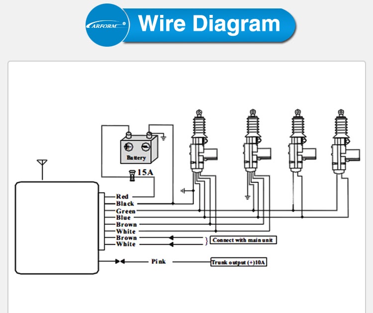
A “Universal Car Alarm Wiring Diagram” refers to a schematic diagram that provides generic instructions for installing a car alarm system. It outlines the connections between the alarm unit, sensors, actuators, and other components. An example is the 5-wire alarm system wiring diagram, where the wires are color-coded for easy identification and simplified installation.
This diagram is significant as it guides technicians in installing car alarm systems across various vehicle makes and models. Its benefits include reduced installation time, improved accuracy, and enhanced system functionality. A key historical development in car alarm wiring diagrams was the standardization of color-coding in the 1990s, which made the diagrams easier to follow and improved installation consistency.
This article will delve further into the components of a universal car alarm wiring diagram, its essential features, and practical applications in the automotive industry.
Understanding the essential aspects of a “Universal Car Alarm Wiring Diagram” is crucial for effective installation and maintenance of car alarm systems. These aspects define the diagram’s structure, function, and application.
- Components: Sensors, actuators, control unit, wiring harness
- Color-Coding: Standardized wire colors for easy identification
- Connections: Schematic representation of component interconnections
- Compatibility: Designed for use with various vehicle makes and models
- Functionality: Outlines system features, such as remote locking/unlocking, alarm triggering
- Installation: Step-by-step guide for proper system setup
- Troubleshooting: Diagnostic information to resolve system issues
- Customization: Options for tailoring the system to specific vehicle requirements
These aspects provide a comprehensive understanding of universal car alarm wiring diagrams. They enable technicians to efficiently install and maintain car alarm systems, ensuring optimal vehicle security and peace of mind for users. The diagram serves as a valuable tool in the automotive industry, facilitating the integration of security systems across a wide range of vehicles.
Components
In the context of a universal car alarm wiring diagram, the componentssensors, actuators, control unit, and wiring harnessplay critical roles in ensuring the system’s functionality and effectiveness. These components work together seamlessly to provide security and protection for vehicles.
The sensors, such as door sensors, motion sensors, and glass break sensors, detect potential intrusions or suspicious activities around the vehicle. They trigger the alarm system when unauthorized entry is attempted, alerting the vehicle owner and deterring potential thieves. Actuators, on the other hand, are responsible for executing the alarm’s response. They activate sirens, flashing lights, or other deterrents to draw attention and scare away intruders.
The control unit serves as the brain of the car alarm system. It receives signals from the sensors, processes them, and commands the actuators to take appropriate actions. The wiring harness, comprising color-coded wires, interconnects all these components, facilitating the flow of signals and power throughout the system. Without these essential components and their proper integration as outlined in the universal car alarm wiring diagram, the alarm system would not function effectively in protecting vehicles and safeguarding their contents.
Color-Coding
Universal Car Alarm Wiring Diagrams utilize color-coding to simplify installation and enhance system functionality. Color standardization ensures consistency across different makes and models of vehicles, enabling technicians to quickly and accurately identify wires during alarm system setup.
- Wire Functions: Each wire color corresponds to a specific function, such as power, ground, sensors, or actuators. This color-coding simplifies wiring, reducing the risk of incorrect connections and system malfunctions.
- Industry Standards: The color-coding follows established industry standards, ensuring that technicians familiar with one wiring diagram can easily understand others. This standardization facilitates knowledge transfer and reduces training time.
- Improved Efficiency: Color-coded wires allow technicians to trace connections and troubleshoot issues more efficiently. The distinct colors provide visual cues, making it easier to locate and repair faults, saving time and effort.
- Reduced Errors: Standardized color-coding minimizes the chances of misidentifying wires, preventing incorrect connections that could compromise the alarm system’s performance or damage vehicle components.
Overall, color-coding in Universal Car Alarm Wiring Diagrams serves as a universal language, enabling technicians to effectively install and maintain car alarm systems, ensuring optimal vehicle security and peace of mind for users.
Connections
In the context of Universal Car Alarm Wiring Diagrams, “Connections: Schematic representation of component interconnections” holds critical importance in ensuring the system’s functionality and effectiveness. A wiring diagram provides a visual representation of how the various components of the alarm system, such as sensors, actuators, and the control unit, are interconnected.
These connections define the pathways for signal and power flow within the system. The schematic representation allows technicians to understand the system’s architecture, trace wire connections, and troubleshoot issues efficiently. Without a clear understanding of these interconnections, proper installation and maintenance of the alarm system would be challenging.
Real-life examples of these connections include the wiring between a door sensor and the control unit, which triggers the alarm when the door is opened unauthorizedly. Another example is the connection between the control unit and the siren, which activates the audible alarm when the system is triggered. These interconnections are essential for the alarm system to function as intended, providing vehicle security and peace of mind to users.
Understanding the connections in a Universal Car Alarm Wiring Diagram is crucial for technicians and installers. It enables them to diagnose and resolve system malfunctions, modify the system’s configuration to meet specific requirements, and integrate additional security devices seamlessly. This understanding contributes to the overall reliability and effectiveness of the vehicle’s security system.
Compatibility
Within the realm of “Universal Car Alarm Wiring Diagram,” the aspect of “Compatibility: Designed for use with various vehicle makes and models” plays a pivotal role. It ensures that the alarm system can be seamlessly integrated with a wide range of vehicles, regardless of their specific makes or models.
- Adaptable Design: Universal car alarm wiring diagrams are designed with flexibility in mind, allowing them to accommodate different vehicle configurations and wiring systems. This adaptability simplifies the installation process and enhances the system’s overall compatibility.
- Standardized Connections: The use of standardized connectors and color-coding in universal car alarm wiring diagrams facilitates compatibility across vehicle makes and models. These standards ensure that the wiring connections are consistent, reducing the risk of errors and ensuring proper system functionality.
- Vehicle-Specific Instructions: To further enhance compatibility, universal car alarm wiring diagrams often include vehicle-specific instructions or supplementary documentation. These instructions provide detailed guidance on how to adapt the wiring diagram to specific vehicle models, taking into account any unique features or variations.
- Versatile Functionality: Universal car alarm wiring diagrams are designed to support a wide range of alarm system functionalities, regardless of the vehicle’s make or model. This versatility ensures that the alarm system can provide consistent protection and security features across different vehicles.
In summary, the compatibility of universal car alarm wiring diagrams stems from their adaptable design, standardized connections, vehicle-specific instructions, and versatile functionality. These factors collectively enable the effective integration of car alarm systems with a diverse range of vehicles, enhancing vehicle security and peace of mind for users.
Functionality
In the context of Universal Car Alarm Wiring Diagrams, the “Functionality: Outlines system features, such as remote locking/unlocking, alarm triggering” plays a vital role in defining the capabilities and effectiveness of the car alarm system. This aspect of the wiring diagram provides a comprehensive overview of the system’s functionalities, including remote locking and unlocking, alarm triggering mechanisms, and other security features.
The functionality section of the wiring diagram serves as a blueprint for the system’s operation. It outlines the connections and configurations required to achieve specific security functions. For instance, the wiring diagram will specify the connections between the remote control transmitter and the control unit, enabling remote locking and unlocking of the vehicle’s doors.
Understanding the functionality aspect of a Universal Car Alarm Wiring Diagram is essential for technicians and installers. It empowers them to customize the alarm system’s features to meet specific requirements and vehicle configurations. For example, they can adjust sensitivity levels, set entry and exit delays, and integrate additional security devices, such as motion sensors or glass break detectors.
Moreover, the functionality section provides valuable insights into the system’s behavior during alarm events. It details the triggering mechanisms for the siren, flashing lights, and other deterrents, ensuring that the system responds appropriately to unauthorized access or suspicious activity.
In summary, the “Functionality: Outlines system features, such as remote locking/unlocking, alarm triggering” aspect of Universal Car Alarm Wiring Diagrams is crucial for understanding the capabilities and operation of the alarm system. It serves as a guide for customization and troubleshooting, enabling technicians and users to tailor the system’s functionality to their specific needs and ensure optimal vehicle security.
Installation
In the realm of Universal Car Alarm Wiring Diagrams, “Installation: Step-by-step guide for proper system setup” holds critical significance as the cornerstone for a successful and effective car alarm system integration. The installation guide provides a comprehensive roadmap for technicians and installers to follow, ensuring that the alarm system is properly configured, connected, and tested for optimal performance and reliability.
The step-by-step nature of the installation guide breaks down the installation process into manageable tasks, each with clear instructions and often accompanied by illustrative diagrams. This structured approach minimizes the risk of errors and omissions, ensuring that even inexperienced installers can achieve professional-grade results.
Real-life examples of the installation guide’s application include:
- Detailed instructions on how to identify and connect the alarm system’s control unit to the vehicle’s electrical system, ensuring a stable and reliable power supply.
- Step-by-step guidance on placing and mounting sensors, such as door sensors, hood sensors, and glass break sensors, in optimal locations for effective detection and triggering.
- Clear instructions on programming the alarm system’s remote control transmitters, ensuring secure and convenient remote locking, unlocking, and alarm activation.
Understanding the connection between “Installation: Step-by-step guide for proper system setup” and “Universal Car Alarm Wiring Diagram” is crucial for technicians and installers to achieve the following practical applications:
- Efficient and accurate installation, reducing the risk of system malfunctions or security vulnerabilities.
- Customization of the alarm system’s features and settings to meet specific vehicle requirements and user preferences.
- Effective troubleshooting and repair in the event of system issues, ensuring prompt restoration of vehicle security.
In summary, the “Installation: Step-by-step guide for proper system setup” is an indispensable component of Universal Car Alarm Wiring Diagrams, providing clear and comprehensive instructions that empower technicians and installers to achieve successful and reliable car alarm system integration. Understanding this connection is essential for ensuring optimal vehicle security and peace of mind for users.
Troubleshooting
In the context of Universal Car Alarm Wiring Diagrams, the connection between “Troubleshooting: Diagnostic information to resolve system issues” and the diagram itself is critical. The troubleshooting section provides essential information to assist technicians and users in diagnosing and resolving system malfunctions, ensuring the alarm system’s optimal performance and reliability.
The diagnostic information typically includes a list of common issues or error codes, along with their potential causes and recommended solutions. For instance, if the alarm system fails to trigger when a door is opened, the troubleshooting guide may suggest checking the door sensor’s wiring connections or replacing the sensor itself. This information empowers users to perform basic troubleshooting steps, reducing the need for professional assistance in some cases.
Moreover, the troubleshooting section serves as a valuable resource for technicians during system installation and maintenance. By understanding potential issues and their solutions, they can proactively address any challenges and minimize system downtime. This practical knowledge contributes to increased efficiency and cost savings for both installers and users.
In summary, the connection between “Troubleshooting: Diagnostic information to resolve system issues” and Universal Car Alarm Wiring Diagrams is crucial for maintaining a fully functional and reliable car alarm system. By providing clear and concise diagnostic information, the troubleshooting section empowers users and technicians to effectively resolve system issues, ensuring optimal vehicle security and peace of mind.
Customization
Within the context of Universal Car Alarm Wiring Diagrams, the aspect of “Customization: Options for tailoring the system to specific vehicle requirements” holds great significance. It empowers users and installers to adapt the alarm system to the unique characteristics and needs of their vehicles, enhancing the system’s effectiveness and overall security.
- Sensor Selection: Universal Car Alarm Wiring Diagrams provide flexibility in selecting and installing sensors based on vehicle type and security preferences. This includes options for door sensors, motion sensors, glass break sensors, and shock sensors, allowing users to customize the level of protection.
- Integration with Vehicle Systems: Customization options allow for seamless integration of the alarm system with other vehicle systems, such as power locks, remote start, and immobilizers. This integration enhances convenience and security, providing comprehensive protection against unauthorized access and theft.
- Sensitivity Adjustment: Universal Car Alarm Wiring Diagrams enable users to adjust the sensitivity of sensors to suit their specific needs. This customization reduces false alarms while ensuring that genuine threats are detected promptly, striking a balance between security and user experience.
- Additional Features: Customization options extend to the inclusion of additional features, such as remote trunk release, panic buttons, and GPS tracking. These features enhance the system’s versatility and cater to specific user requirements.
In summary, “Customization: Options for tailoring the system to specific vehicle requirements” is a crucial aspect of Universal Car Alarm Wiring Diagrams. It provides users and installers with the flexibility to adapt the alarm system to their unique needs, ensuring optimal protection and security for their vehicles.


Related Posts


