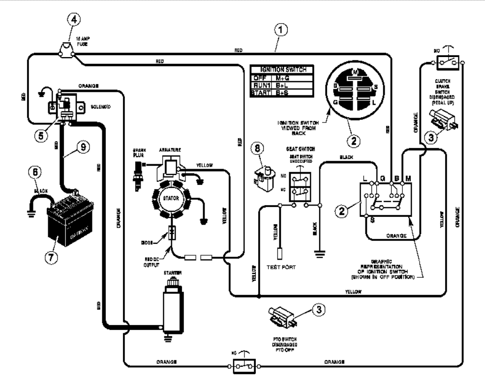
A Twin Briggs and Stratton Wiring Diagram is a schematic representation of the electrical connections in a Briggs and Stratton engine with two cylinders. It provides a visual guide to the electrical components, wiring harness, and connectors, enabling technicians to troubleshoot and repair electrical issues.
Wiring diagrams are crucial for servicing engines as they allow technicians to identify and locate electrical problems. They enhance efficiency, reduce repair time, and ensure the safe functioning of the engine. The standardization of wiring diagrams across Briggs and Stratton engines streamlines the troubleshooting process.
The introduction of computer-aided design (CAD) software in the 1980s revolutionized the creation of wiring diagrams. CAD tools enabled precise and efficient drawing, facilitating the production of accurate and detailed diagrams.
Understanding the essential aspects of Twin Briggs and Stratton Wiring Diagrams is crucial for effective engine maintenance and troubleshooting. These diagrams provide a comprehensive overview of the electrical connections, enabling technicians to identify and resolve issues efficiently.
- Components: Major electrical components, such as the ignition coil, starter solenoid, and voltage regulator.
- Wiring: Types and colors of wires used in the harness, ensuring proper connections.
- Connectors: Different types of connectors, including spade terminals, bullet connectors, and multi-pin plugs.
- Grounding: Points where the electrical system is connected to the engine block or frame.
- Testing: Techniques for testing electrical components and circuits, using multimeters and other tools.
- Troubleshooting: Steps involved in diagnosing and resolving electrical problems.
- Safety: Precautions to take when working on electrical systems, including proper grounding and insulation.
- Standards: Industry standards and best practices for electrical wiring in Briggs and Stratton engines.
- Documentation: Importance of maintaining accurate wiring diagrams for future reference and repair.
- Training: Resources and training programs available for technicians to enhance their skills in electrical diagnostics.
These aspects are interconnected and essential for understanding the functionality and maintenance of Twin Briggs and Stratton engines. Wiring diagrams serve as a valuable tool for technicians, enabling them to diagnose and resolve electrical issues efficiently and safely.
Components
In the context of Twin Briggs and Stratton Wiring Diagrams, understanding the major electrical components is essential for effective troubleshooting and maintenance. These components play crucial roles in the proper functioning of the engine’s electrical system.
-
Ignition Coil:
The ignition coil generates the high voltage required to create a spark in the spark plugs, initiating combustion. A faulty ignition coil can lead to engine misfires or failure to start.
-
Starter Solenoid:
The starter solenoid engages the starter motor with the engine’s flywheel, allowing the engine to crank and start. A malfunctioning starter solenoid can prevent the engine from starting.
-
Voltage Regulator:
The voltage regulator controls the voltage output of the charging system, preventing overcharging or undercharging of the battery. A faulty voltage regulator can damage the battery or other electrical components.
These components, along with other electrical parts such as the battery, alternator, and wiring harness, form the electrical system of the Briggs and Stratton engine. A thorough understanding of these components and their interconnections, as depicted in the wiring diagram, is crucial for diagnosing and resolving electrical issues efficiently.
Wiring
In the context of Twin Briggs and Stratton Wiring Diagrams, the types and colors of wires used in the harness play a critical role in ensuring proper electrical connections and functionality. The wiring diagram serves as a visual guide, providing a comprehensive overview of the electrical system, including the types and colors of wires used.
Understanding the different types of wires is essential for proper identification and troubleshooting. For instance, heavier gauge wires are used for high-current applications, such as the starter motor circuit, while lighter gauge wires are used for low-current applications, such as sensor circuits. Additionally, color-coding the wires simplifies the identification of specific circuits, making it easier to trace and diagnose electrical issues.
Real-life examples within Twin Briggs and Stratton Wiring Diagrams demonstrate the practical applications of understanding wire types and colors. For example, the ignition circuit typically uses a red wire, the charging circuit uses a yellow wire, and the ground circuit uses a black wire. By recognizing these color-coding conventions, technicians can quickly identify and troubleshoot electrical problems.
The practical significance of this understanding extends to the efficient maintenance and repair of Briggs and Stratton engines. Accurate wiring diagrams, coupled with a clear understanding of wire types and colors, enable technicians to diagnose and resolve electrical faults quickly and accurately. This not only reduces repair time but also ensures the safe and reliable operation of the engine.
Connectors
Within the context of Twin Briggs and Stratton Wiring Diagrams, connectors play a vital role in establishing secure electrical connections between various components of the engine’s electrical system. Understanding the different types of connectors used is essential for proper wiring, troubleshooting, and maintenance.
-
Spade Terminals:
Spade terminals, also known as spade connectors, are U-shaped terminals with a narrow tongue that slides onto the male terminal of a matching connector. They are commonly used for low-current applications, such as connecting switches and sensors.
-
Bullet Connectors:
Bullet connectors are cylindrical terminals with a male and female end that are crimped onto the ends of wires. They are often used for quick and temporary connections, such as when testing electrical circuits or connecting accessories.
-
Multi-Pin Plugs:
Multi-pin plugs are connectors with multiple male or female terminals arranged in a specific configuration. They are used to connect multiple wires simultaneously, simplifying wiring and reducing the risk of incorrect connections.
-
Ring Terminals:
Ring terminals are circular terminals with a hole in the center that allows them to be bolted or screwed onto a stud or terminal block. They are commonly used for high-current applications, such as connecting the battery to the starter solenoid.
These connectors, along with other types such as butt connectors and quick-disconnect connectors, play a critical role in ensuring the proper functioning of the electrical system in Twin Briggs and Stratton engines. Understanding their types, applications, and proper installation techniques is essential for effective troubleshooting and maintenance.
Grounding
In the context of Twin Briggs and Stratton Wiring Diagrams, grounding plays a critical role in ensuring the proper functioning and safety of the electrical system. Grounding refers to the electrical connection between the electrical system and the metal frame or block of the engine. This connection provides a common reference point for electrical circuits and prevents the accumulation of stray voltage.
-
Battery Ground:
The battery’s negative terminal is connected to the engine block or frame, providing a direct path for current to return to the battery. This ensures that the electrical system has a stable reference point and prevents voltage fluctuations.
-
Engine Block Ground:
The engine block itself serves as a grounding point for many electrical components, such as the starter motor and sensors. These components are connected to the engine block through bolts or brackets, which provide a secure electrical connection. Proper grounding of the engine block is essential for preventing electrical interference and ensuring reliable operation.
-
Frame Ground:
In some cases, the metal frame of the engine is also used as a grounding point. This is particularly important for components mounted on the frame, such as lights and accessories. Frame grounding helps to dissipate electrical noise and ensures proper operation of these components.
-
Grounding Points:
Specific points on the engine block or frame are designated as grounding points. These points provide a convenient and reliable location to connect grounding wires from various electrical components. Grounding points are often marked with a symbol or label to indicate their purpose.
Proper grounding is essential for the safe and efficient operation of the electrical system in Twin Briggs and Stratton engines. By providing a common reference point and preventing voltage fluctuations, grounding ensures that electrical components function as intended and that the engine operates reliably. Understanding the concept of grounding and the various grounding points is crucial for effective troubleshooting and maintenance of these engines.
Testing
Testing electrical components and circuits is a critical aspect of understanding and maintaining Twin Briggs and Stratton engines. By utilizing multimeters and other diagnostic tools, technicians can effectively troubleshoot and pinpoint issues within the electrical system, ensuring optimal engine performance and reliability.
-
Continuity Testing:
This technique verifies the continuity of an electrical circuit, indicating whether there is a complete path for current to flow. Using a multimeter set to the continuity setting, technicians can check for open circuits or poor connections that may disrupt the flow of electricity.
-
Voltage Testing:
Voltage testing measures the electrical potential difference between two points in a circuit. Technicians use multimeters to measure voltage levels at various points in the electrical system, such as the battery terminals, alternator output, and ignition coil, to ensure that components are receiving the correct voltage for proper operation.
-
Resistance Testing:
Resistance testing determines the resistance of a component or circuit to the flow of electricity. Using a multimeter set to the ohms setting, technicians can measure the resistance of components such as ignition coils, sensors, and wiring harnesses to identify faults or excessive resistance that may affect engine performance.
-
Component Testing:
Specific testing procedures are used to evaluate the functionality of individual electrical components. For instance, technicians may use a spark tester to check the ignition coil’s ability to generate sparks or a fuel injector tester to verify the proper operation of fuel injectors.
These testing techniques, along with the proper use of multimeters and other diagnostic tools, provide valuable insights into the electrical system of Twin Briggs and Stratton engines. By effectively testing electrical components and circuits, technicians can accurately diagnose and resolve electrical issues, ensuring the engine operates at its peak efficiency and reliability.
Troubleshooting
When delving into Twin Briggs and Stratton Wiring Diagrams, troubleshooting electrical problems is a crucial aspect that requires a systematic approach to identify and resolve electrical faults effectively. Troubleshooting involves a series of steps that enable technicians to pinpoint the root cause of electrical issues, ensuring the optimal performance and reliability of the engine.
-
Identifying Symptoms:
The initial step in troubleshooting is to identify and document the symptoms of the electrical problem. This includes observing any warning lights, listening for unusual noises, and noting any changes in engine performance. Accurate identification of symptoms provides valuable clues for further diagnosis.
-
Visual Inspection:
A thorough visual inspection of the electrical system is essential to identify any obvious issues such as loose connections, damaged wires, or faulty components. This involves examining the wiring harness, connectors, and electrical components for any signs of wear, corrosion, or damage.
-
Electrical Testing:
Using a multimeter and other diagnostic tools, technicians perform electrical tests to evaluate the functionality of individual components and circuits. This includes testing for continuity, voltage, and resistance to identify faults within the electrical system. Electrical testing provides quantitative data to pinpoint the source of the electrical problem.
-
Component Replacement:
Once the faulty electrical component or circuit is identified, the next step is to replace it with a new or one. This requires careful attention to detail and adherence to the manufacturer’s guidelines to ensure proper installation and functionality.
By following these troubleshooting steps and utilizing the Twin Briggs and Stratton Wiring Diagram as a reference, technicians can effectively diagnose and resolve electrical problems, ensuring the reliable operation of the engine. Troubleshooting electrical issues requires a combination of technical knowledge, analytical skills, and a systematic approach to identify and resolve faults accurately.
Safety
When working with Twin Briggs and Stratton Wiring Diagrams, safety should be of paramount importance. Electrical systems pose potential hazards, and adhering to proper safety precautions is crucial to prevent accidents and ensure the well-being of individuals performing electrical work.
-
Proper Grounding:
Grounding provides a safe path for electrical current to flow in the event of a fault. Improper grounding can result in electrical shocks or damage to equipment. Twin Briggs and Stratton Wiring Diagrams clearly indicate grounding points, ensuring proper grounding of the electrical system.
-
Insulated Tools and Equipment:
Using insulated tools and equipment is essential to prevent electrical shocks. Insulated materials create a barrier between the electrical current and the individual handling the tools. Wiring diagrams often specify the insulation requirements for specific components.
-
Protective Clothing:
Wearing appropriate protective clothing, such as rubber gloves and safety glasses, can further minimize the risk of electrical shocks or injury. These protective measures are crucial when working with exposed electrical components.
-
Safe Work Environment:
Working in a safe environment is equally important. Ensuring adequate ventilation and avoiding wet or slippery surfaces can prevent accidents. Wiring diagrams often include notes and warnings to alert technicians to potential hazards.
Understanding and implementing these safety precautions is essential when working with Twin Briggs and Stratton Wiring Diagrams. By following these guidelines, technicians can minimize the risks associated with electrical work, ensuring a safe and efficient work environment.
Standards
Within the realm of Twin Briggs and Stratton Wiring Diagrams, industry standards and best practices for electrical wiring play a critical role in ensuring the safety, reliability, and performance of Briggs and Stratton engines. These standards provide a framework for electrical system design, installation, and maintenance, ensuring consistency and adherence to established guidelines.
The Twin Briggs and Stratton Wiring Diagram serves as a visual representation of the electrical system, incorporating industry standards and best practices. By following these standards, manufacturers and technicians can ensure that the electrical system is wired correctly, reducing the risk of electrical faults, fires, and other hazards. For instance, the use of color-coded wires, proper grounding techniques, and appropriate wire gauges are all guided by industry standards.
Understanding these standards is crucial for technicians working with Twin Briggs and Stratton Wiring Diagrams. Adhering to best practices ensures that electrical repairs and modifications are performed safely and effectively. By utilizing the diagram in conjunction with a thorough understanding of industry standards, technicians can troubleshoot electrical issues accurately, identify potential hazards, and implement effective solutions.
In summary, industry standards and best practices for electrical wiring in Briggs and Stratton engines are essential components of Twin Briggs and Stratton Wiring Diagrams. These standards ensure the safety, reliability, and performance of the electrical system, guiding manufacturers and technicians in the proper design, installation, and maintenance of Briggs and Stratton engines.
Documentation
Within the context of Twin Briggs and Stratton Wiring Diagrams, documentation plays a critical role in ensuring the long-term reliability and serviceability of Briggs and Stratton engines. Accurate wiring diagrams serve as a valuable reference for technicians, enabling them to troubleshoot electrical issues, perform repairs, and modify the electrical system as needed. Without proper documentation, troubleshooting and repair tasks become significantly more challenging, time-consuming, and prone to errors.
The Twin Briggs and Stratton Wiring Diagram serves as a central component of the engine’s documentation, providing a comprehensive overview of the electrical system’s design and configuration. By maintaining accurate and up-to-date wiring diagrams, manufacturers and technicians can ensure that the electrical system is properly maintained, repaired, and modified throughout the engine’s lifespan. Regular updates to the wiring diagram reflect changes made to the electrical system, ensuring that the documentation remains accurate and reliable.
Real-life examples of the importance of accurate wiring diagrams are prevalent in the maintenance and repair of Twin Briggs and Stratton engines. For instance, if an electrical fault occurs, a technician can refer to the wiring diagram to identify the affected circuit, locate the faulty component, and determine the appropriate repair procedure. Without an accurate wiring diagram, the troubleshooting process becomes more time-consuming and may lead to incorrect repairs or further damage to the electrical system.
In summary, documentation, particularly the maintenance of accurate wiring diagrams, is a critical aspect of Twin Briggs and Stratton Wiring Diagrams. It enables effective troubleshooting, efficient repairs, and informed modifications to the electrical system. By emphasizing the importance of documentation, manufacturers and technicians can ensure the long-term reliability, serviceability, and safety of Briggs and Stratton engines.
Training
Within the context of Twin Briggs and Stratton Wiring Diagrams, training and resources play a critical role in enhancing technicians’ skills in electrical diagnostics. The complexity of modern electrical systems demands that technicians possess a comprehensive understanding of electrical principles, diagnostic techniques, and safety procedures to effectively troubleshoot and repair electrical faults.
Training programs provide technicians with the necessary knowledge and hands-on experience to interpret Twin Briggs and Stratton Wiring Diagrams accurately, identify electrical faults, and perform repairs efficiently. These programs cover topics such as electrical theory, circuit analysis, component testing, and diagnostic procedures. By participating in training programs, technicians gain the skills and confidence to work safely and effectively on electrical systems.
Real-life examples of the importance of training in electrical diagnostics are evident in the maintenance and repair of Twin Briggs and Stratton engines. Technicians who have undergone comprehensive training are better equipped to diagnose and resolve electrical issues, reducing downtime and ensuring optimal engine performance. They can accurately identify faulty components, trace electrical circuits, and implement appropriate repair strategies to restore the electrical system to proper working order.
In summary, training and resources for electrical diagnostics are essential components of Twin Briggs and Stratton Wiring Diagrams. By enhancing their skills through training, technicians gain the knowledge and expertise to effectively troubleshoot, repair, and maintain electrical systems, ensuring the reliability and performance of Briggs and Stratton engines.


Related Posts


