Troubleshooting Thermostat Wiring defines the process of identifying and rectifying issues within the electrical connections of a thermostat. This wiring ensures proper communication between the thermostat and the heating, ventilation, and air conditioning (HVAC) system to maintain desired temperature levels.
Troubleshooting thermostat wiring plays a crucial role in ensuring efficient and comfortable indoor conditions. By resolving wiring problems, it helps prevent system malfunctions, energy wastage, and potential safety hazards. Historically, the advent of digital thermostats brought about significant advancements, allowing for more precise temperature control and advanced diagnostic features that facilitate troubleshooting.
In this article, we will delve into the techniques and considerations involved in troubleshooting thermostat wiring, examining common issues, and providing guidance on effective solutions.
Troubleshooting thermostat wiring is a crucial aspect of maintaining optimal indoor comfort and energy efficiency. Understanding the key aspects involved in this process is essential for effective problem-solving and ensuring the proper functioning of HVAC systems.
- Electrical Safety: Adhering to electrical codes and safety protocols to prevent electrical hazards.
- Wiring Diagram Interpretation: Comprehending the electrical schematics specific to the thermostat model.
- Multimeter Usage: Employing a multimeter to test voltage, continuity, and resistance within the wiring.
- Common Wire Identification: Distinguishing between different types of wires (e.g., power, signal, ground) based on color coding and labeling.
- Thermostat Compatibility: Ensuring compatibility between the thermostat and the HVAC system, considering voltage, amperage, and communication protocols.
- Error Code Interpretation: Understanding and deciphering error codes displayed by the thermostat to identify specific issues.
- Loose Connections: Identifying and tightening any loose connections within the wiring, which can cause intermittent or complete system failure.
- Short Circuits: Detecting and resolving short circuits that can disrupt electrical flow and damage components.
- Ground Faults: Troubleshooting ground faults that can lead to electrical leakage and safety concerns.
- Advanced Diagnostics: Utilizing advanced diagnostic tools and techniques to pinpoint complex wiring issues and ensure accurate repairs.
These key aspects provide a comprehensive framework for troubleshooting thermostat wiring effectively. By considering these factors, technicians and homeowners can identify and resolve wiring problems, ensuring optimal system performance, energy efficiency, and occupant comfort.
Electrical Safety
In the context of troubleshooting thermostat wiring, electrical safety plays a paramount role in ensuring the protection of individuals and property. By adhering to established electrical codes and safety protocols, potential electrical hazards can be prevented, safeguarding against electrical shocks, fires, and other dangerous situations.
Electrical safety is a critical component of troubleshooting thermostat wiring, as incorrect wiring or faulty connections can lead to electrical issues. These issues can manifest in various forms, including short circuits, ground faults, and loose connections, which can disrupt the proper functioning of the thermostat and HVAC system. Moreover, electrical hazards pose a significant safety risk, emphasizing the importance of following safety protocols and utilizing appropriate tools and equipment during troubleshooting.
For instance, when troubleshooting thermostat wiring, it is imperative to verify that all electrical connections are secure and properly insulated to prevent short circuits. Additionally, ensuring that the thermostat is compatible with the electrical system and wiring configuration is crucial. This involves checking the voltage, amperage, and communication protocols to guarantee safe and efficient operation.
Understanding the relationship between electrical safety and troubleshooting thermostat wiring enables technicians and homeowners to approach this task with the necessary precautions. By prioritizing electrical safety, potential hazards can be mitigated, ensuring the safe and effective resolution of thermostat wiring issues.
Wiring Diagram Interpretation
Wiring diagram interpretation is a critical aspect of troubleshooting thermostat wiring, providing a visual representation of the electrical connections and components within a thermostat. By comprehending these schematics, technicians can effectively identify and resolve wiring issues, ensuring the proper functioning of the HVAC system.
- Component Identification: Wiring diagrams enable the identification of various components within the thermostat, including terminals, switches, resistors, and capacitors. This understanding helps technicians locate and test specific components to pinpoint wiring problems.
- Circuit Tracing: Diagrams provide a roadmap for tracing electrical circuits, allowing technicians to follow the flow of electricity through the thermostat. This helps identify open circuits, short circuits, and other wiring faults that may disrupt thermostat operation.
- Compatibility Verification: Wiring diagrams are essential for verifying the compatibility between the thermostat and the HVAC system. By comparing the diagram with the system’s electrical specifications, technicians can ensure that the thermostat is properly wired and configured for the specific application.
- Error Code Troubleshooting: Some thermostats display error codes to indicate wiring issues. Wiring diagrams provide a reference for interpreting these codes, allowing technicians to quickly identify the source of the problem and implement appropriate solutions.
Overall, wiring diagram interpretation empowers technicians with a deep understanding of the electrical connections within a thermostat, enabling them to diagnose and resolve wiring issues efficiently. By accurately interpreting these schematics, technicians can ensure the reliable operation of thermostats, maintaining optimal indoor comfort and energy efficiency.
Multimeter Usage
When troubleshooting thermostat wiring, employing a multimeter is a crucial step in diagnosing and resolving electrical issues. This versatile tool allows technicians to test voltage, continuity, and resistance within the wiring, providing valuable insights into the functionality of the thermostat and its connections.
- Voltage Testing: Using a multimeter, technicians can measure the voltage at various points in the thermostat circuit to ensure that power is flowing correctly. This helps identify issues such as open circuits, loose connections, or faulty components that may disrupt the thermostat’s operation.
- Continuity Testing: Continuity testing involves using a multimeter to check if a complete electrical path exists between two points in the circuit. This test is essential for identifying breaks or interruptions in the wiring, ensuring that current can flow freely through the thermostat and its components.
- Resistance Testing: Resistance testing measures the opposition to the flow of electrical current in a circuit. By testing resistance, technicians can identify potential problems such as shorts or high resistance connections that can affect the thermostat’s performance and efficiency.
- Component Testing: Multimeters can also be used to test individual components within the thermostat, such as switches, sensors, and relays. This helps isolate faulty components and determine if they need to be replaced, ensuring the overall functionality of the thermostat.
In summary, multimeter usage is an indispensable aspect of troubleshooting thermostat wiring, allowing technicians to accurately diagnose electrical issues and implement effective solutions. By testing voltage, continuity, and resistance, technicians can pinpoint problems, identify faulty components, and restore the proper functioning of the thermostat, ensuring optimal temperature control and energy efficiency.
Common Wire Identification
In the context of “Troubleshooting Thermostat Wiring”, “Common Wire Identification: Distinguishing between different types of wires (e.g., power, signal, ground) based on color coding and labeling” plays a fundamental role in ensuring proper electrical connections and system functionality. This process involves identifying and differentiating various types of wires based on their color coding and labeling, facilitating accurate wiring and resolving issues during troubleshooting.
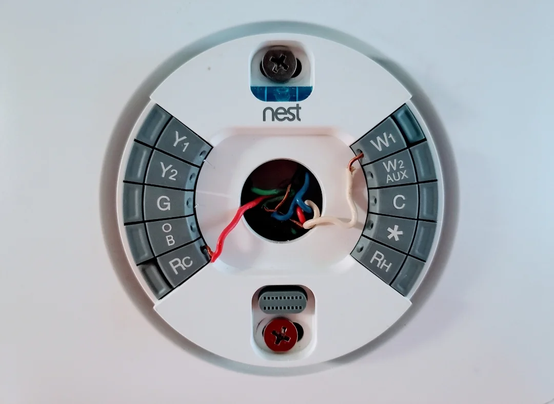
- Wire Color Coding: Thermostat wires are typically color-coded to indicate their function. For instance, red wires often denote power, white wires represent neutral, green wires indicate ground, and yellow wires may signify a signal or data connection. Understanding these color codes is crucial for correct wiring and troubleshooting.
- Wire Labeling: In addition to color coding, wires may also be labeled with specific markings or numbers. These labels provide further clarification on the wire’s purpose and can assist in tracing connections during troubleshooting, especially when dealing with multiple wires of the same color.
- Grounding Wires: Grounding wires play a critical safety role by providing a path for excess electrical current to flow safely into the ground, preventing electrical shocks and damage to equipment. Identifying and connecting grounding wires correctly is essential for ensuring the safe operation of the thermostat and HVAC system.
- Signal Wires: Signal wires transmit data and communication signals between the thermostat and other components of the HVAC system, such as sensors or actuators. Correctly identifying and connecting signal wires is crucial for ensuring proper communication and control within the system.
By understanding and applying common wire identification techniques, technicians can accurately troubleshoot wiring issues, ensuring reliable and efficient operation of the thermostat and HVAC system. This involves carefully examining wire colors, interpreting labels, and verifying proper grounding and signal connections, ultimately leading to a successful troubleshooting process and a comfortable indoor environment.
Thermostat Compatibility
In the realm of “Troubleshooting Thermostat Wiring,” “Thermostat Compatibility: Ensuring compatibility between the thermostat and the HVAC system, considering voltage, amperage, and communication protocols” holds paramount importance. It establishes a harmonious relationship between the thermostat and the intricate components of the HVAC system, ensuring efficient and reliable operation. Understanding this aspect is vital for successful troubleshooting and maintaining a comfortable indoor environment.
- Voltage Compatibility: The voltage rating of the thermostat must align with the voltage of the HVAC system. Mismatches can lead to incorrect operation, damage to components, or even safety hazards. For instance, a 24-volt thermostat connected to a 120-volt system may malfunction or pose an electrical risk.
- Amperage Requirements: The thermostat must be able to handle the amperage draw of the connected HVAC equipment. Exceeding the amperage rating can overload the thermostat, causing overheating, damage, or electrical fires. Proper sizing ensures safe and efficient operation.
- Communication Protocols: Different thermostats and HVAC systems employ specific communication protocols to exchange data and control commands. Compatibility is crucial to ensure seamless communication. For example, a Wi-Fi-enabled thermostat requires a compatible HVAC system with a Wi-Fi receiver to enable remote control and monitoring.
Comprehending these facets of thermostat compatibility empowers technicians and homeowners to make informed decisions when troubleshooting wiring issues. By carefully considering voltage, amperage, and communication protocols, they can ensure that the thermostat and HVAC system work together flawlessly, delivering optimal comfort and energy efficiency.
Error Code Interpretation
Error code interpretation plays a critical role in troubleshooting thermostat wiring. When a thermostat encounters an issue, it often displays an error code on its display. These codes provide valuable information about the nature of the problem, enabling technicians and homeowners to quickly identify and address the underlying cause.
For instance, a common error code is “E1,” which typically indicates a communication error between the thermostat and the HVAC system. By interpreting this error code, a technician can narrow down the troubleshooting process and focus on checking the wiring connections, ensuring they are secure and making good contact.
Another example is an error code of “H2,” which may indicate a high-temperature limit fault. This error code would prompt the technician to inspect the temperature sensor and wiring to ensure they are functioning correctly and not causing false readings.
Understanding error codes is essential for effective thermostat wiring troubleshooting. By deciphering these codes, technicians can save time and effort by pinpointing the specific issue rather than resorting to trial-and-error methods. This leads to faster and more accurate repairs, minimizing discomfort for occupants and reducing the likelihood of more severe problems developing.
Loose Connections
Loose connections within the wiring of a thermostat system can lead to a wide range of issues, from intermittent operation to complete system failure. Loose connections occur when the electrical contacts between two or more wires are not properly secured, resulting in poor electrical flow and potential arcing. This can cause the thermostat to malfunction, leading to inaccurate temperature readings, improper control of the HVAC system, and even safety hazards.
Identifying and tightening loose connections is a critical aspect of troubleshooting thermostat wiring. Loose connections can develop over time due to vibration, thermal expansion and contraction, or improper installation. By carefully inspecting the wiring connections and ensuring they are securely fastened, technicians can eliminate loose connections as a potential source of problems.
For example, a loose connection in the wiring between the thermostat and the HVAC system’s control board can cause intermittent communication errors, resulting in the thermostat being unable to properly control the heating or cooling system. This can lead to uncomfortable temperature fluctuations and increased energy consumption.
Understanding the connection between loose connections and thermostat wiring troubleshooting is essential for both homeowners and technicians. By recognizing the symptoms of loose connections, such as intermittent operation, erratic temperature control, or error messages, individuals can take prompt action to identify and tighten the loose connections, restoring the thermostat system to proper working order and ensuring a comfortable and energy-efficient indoor environment.
Short Circuits
In the realm of “Troubleshooting Thermostat Wiring,” addressing short circuits is a crucial aspect that directly impacts system functionality and safety. Short circuits occur when an unintended, low-resistance path is created between two points in an electrical circuit, causing a sudden surge in current flow. This can lead to a range of issues, from disruption of electrical flow and component damage to potential fire hazards.
- Identification: Short circuits are often accompanied by symptoms such as blown fuses, tripped circuit breakers, or overheating wires. Detecting short circuits requires careful inspection of the wiring, looking for signs of damage, loose connections, or insulation breaches.
- Consequences: The consequences of short circuits can vary depending on the severity of the short and the components involved. Minor short circuits may only cause temporary disruption, while more severe ones can lead to permanent damage to the thermostat or other electrical components.
- Causes: Short circuits can be caused by various factors, including loose connections, damaged insulation, or faulty components. Identifying the root cause of the short circuit is essential to prevent recurrence.
Understanding and addressing short circuits is a fundamental aspect of troubleshooting thermostat wiring. By recognizing the symptoms, potential consequences, and common causes, technicians and homeowners can effectively resolve short circuits, ensuring the safe and efficient operation of the thermostat and HVAC system.
Ground Faults
In the realm of “Troubleshooting Thermostat Wiring,” addressing ground faults is a crucial aspect that directly impacts the safety and reliability of the electrical system. Ground faults occur when an unintended path is created between an electrical circuit and the ground, leading to a potentially dangerous flow of electricity.
- Electrical Leakage: Ground faults can cause electrical leakage, which occurs when current flows through unintended paths, leading to energy loss, reduced efficiency, and potential electrical shocks.
- Tripped Circuit Breakers: Ground faults can cause circuit breakers to trip, interrupting the flow of electricity to protect the circuit and prevent damage to components.
- Electrical Fires: Severe ground faults can generate excessive heat, potentially leading to electrical fires if not addressed promptly.
- Safety Hazards: Ground faults pose a significant safety hazard, as they can result in electrical shocks, burns, and electrocution.
Understanding and troubleshooting ground faults is essential for ensuring the safe and proper operation of thermostat wiring. By recognizing the symptoms, potential consequences, and common causes of ground faults, technicians and homeowners can effectively resolve these issues, preventing electrical hazards and ensuring a reliable and energy-efficient HVAC system.
Advanced Diagnostics
In the realm of “Troubleshooting Thermostat Wiring,” “Advanced Diagnostics: Utilizing advanced diagnostic tools and techniques to pinpoint complex wiring issues and ensure accurate repairs” stands as a critical component, empowering technicians and homeowners to resolve intricate wiring problems effectively. This involves employing specialized tools and techniques to identify and rectify faults that may not be readily apparent through basic troubleshooting methods.
Advanced diagnostic tools, such as digital multimeters, oscilloscopes, and thermal imaging cameras, provide deeper insights into the electrical signals and system behavior, enabling technicians to pinpoint the exact location and nature of wiring issues. These tools allow for precise measurements, waveform analysis, and temperature monitoring, revealing hidden problems that may otherwise go unnoticed.
For instance, using an oscilloscope to analyze the electrical signals in a thermostat circuit can help identify intermittent faults or signal distortions that may be causing erratic thermostat behavior. Thermal imaging cameras can detect temperature variations along wiring connections, indicating potential loose connections or insulation damage that could lead to short circuits or other problems.
By utilizing advanced diagnostics, technicians can avoid unnecessary guesswork and trial-and-error approaches, leading to faster and more accurate repairs. This not only enhances the efficiency of troubleshooting but also minimizes system downtime, reduces the risk of further damage, and ensures optimal performance of the thermostat and HVAC system.


Related Posts


