A trim motor wiring 3-wire tilt trim diagram is a detailed schematic representation of the electrical connections for a tilt and trim system, specifically with a 3-wire trim motor. It visually illustrates how the motor, switch, and power source are interconnected.
Understanding this diagram is crucial for proper installation, troubleshooting, and repair of tilt and trim systems in marine applications. It ensures that the system functions smoothly, allowing for efficient boat handling and safety during operation. Furthermore, the advent of waterproof connectors in tilt and trim wiring harnesses has significantly enhanced the reliability and longevity of these systems in marine environments.
In this article, we will delve deeper into the intricacies of a trim motor wiring 3-wire tilt trim diagram, providing a comprehensive guide to its components, functionality, and practical applications.
Trim motor wiring 3 wire tilt trim diagrams are essential for understanding, installing, and maintaining tilt and trim systems in marine applications. These diagrams provide a visual representation of the electrical connections between the trim motor, switch, and power source. Understanding the key aspects of these diagrams is crucial for ensuring the proper functioning and safety of tilt and trim systems.
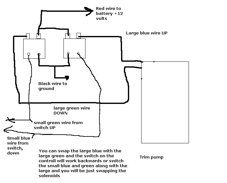
- Components: Trim motor, switch, power source, wires, connectors
- Wiring: 3-wire configuration for trim motor control
- Functionality: Tilt and trim boat engine for optimal performance and safety
- Safety: Waterproof connectors prevent electrical hazards in marine environments
- Installation: Diagram guides proper installation for reliable operation
- Troubleshooting: Diagram aids in diagnosing and repairing system faults
- Maintenance: Regular inspection and maintenance based on diagram recommendations
- Efficiency: Optimized boat handling and fuel efficiency through proper trim
In summary, trim motor wiring 3 wire tilt trim diagrams are essential for the proper installation, maintenance, and troubleshooting of tilt and trim systems. By understanding the components, wiring, functionality, and other key aspects of these diagrams, boat owners and technicians can ensure the safe and efficient operation of their marine vessels.


![[DIAGRAM] Mercruiser Tilt Trim Diagram](https://i0.wp.com/d3d71ba2asa5oz.cloudfront.net/32001220/images/wh-001b2.jpg?w=665&ssl=1)

Related Posts


