Travel Trailer 50 Amp RV Plug Wiring Diagram refers to a detailed schematic that illustrates the electrical connections between a 50-amp shore power receptacle and the RV’s electrical system. For instance, an RV park’s 50-amp outlet typically provides three 120-volt lines and one neutral line for larger RVs.
The wiring diagram is crucial for ensuring safe and proper electrical connections. It helps identify the correct wire colors to connect to the appropriate terminals on the plug and RV’s electrical panel. Benefits include preventing electrical hazards, optimizing RV power usage, and conforming to electrical codes.
Historically, the development of standardized RV electrical systems, including the 50-amp plug wiring, has significantly enhanced the safety and convenience of RV travel. The article will delve into the specifics of 50-amp RV plug wiring diagrams, their components, and best practices for proper installation and maintenance.
Understanding the essential aspects of “Travel Trailer 50 Amp RV Plug Wiring Diagram” is crucial for the safe and effective installation and maintenance of RV electrical systems.
- Wiring Configuration: Specifies the arrangement of wires within the plug.
- Amperage Rating: Indicates the maximum current capacity of the plug (50 amps).
- Voltage Compatibility: Ensures the plug is compatible with the RV’s electrical system (120/240 volts).
- Plug Type: Identifies the specific type of plug used (NEMA 14-50).
- Wire Gauge: Determines the thickness of the wires used in the plug.
- Color Coding: Standardizes the colors of wires for easy identification.
- Grounding: Provides a safe path for electrical faults.
- Safety Features: Includes measures like surge protection and weatherproofing.
These aspects are interconnected and impact the overall functionality and safety of the RV’s electrical system. For instance, using the correct wire gauge ensures proper current flow, while proper grounding protects against electrical shocks. Understanding these aspects empowers RV owners and technicians to make informed decisions when working with 50-amp RV plug wiring diagrams.
Wiring Configuration
In the context of “Travel Trailer 50 Amp RV Plug Wiring Diagram,” the wiring configuration is a crucial aspect that governs the safe and efficient flow of electrical current within the RV’s electrical system. The arrangement of wires within the plug determines the proper connection between the RV’s electrical panel and the external power source, ensuring that the RV’s appliances and systems receive the appropriate power supply.
A typical 50-amp RV plug consists of four prongs: two hot lines (usually black and red), a neutral line (white), and a ground line (green). The wiring configuration specifies the order in which these wires are arranged within the plug, ensuring proper polarity and preventing electrical hazards. For instance, if the hot and neutral wires are reversed, it could lead to incorrect voltage distribution and potential damage to the RV’s electrical system.
Understanding the wiring configuration is essential for proper installation and maintenance of RV electrical systems. When connecting the RV to an external power source, the wiring configuration of the plug must match the wiring configuration of the receptacle to ensure a secure and functional connection. Incorrect wiring can result in power outages, electrical shorts, or even fires.
In summary, the wiring configuration of a 50-amp RV plug plays a critical role in ensuring the safe and efficient operation of the RV’s electrical system. Proper understanding and adherence to the specified wiring configuration are essential for maintaining the integrity and functionality of the RV’s electrical system.
Amperage Rating
In the context of “Travel Trailer 50 Amp RV Plug Wiring Diagram,” the amperage rating is a critical specification that establishes the maximum current-carrying capacity of the plug, which is typically 50 amps. Understanding the amperage rating is essential for ensuring the safe and efficient operation of the RV’s electrical system.
- Electrical Capacity: The amperage rating determines the maximum amount of electrical current that the plug and its associated wiring can safely handle. Exceeding the amperage rating can lead to overheating, damage to the electrical system, and potential fire hazards.
- RV Power Requirements: The amperage rating of the plug must match the power requirements of the RV. Larger RVs with multiple appliances and systems typically require higher amperage ratings (e.g., 30 amps or 50 amps) to meet their electrical demands.
- Compatibility with External Power Sources: RV parks and campgrounds often provide electrical hookups with varying amperage ratings. The plug’s amperage rating must be compatible with the available power source to ensure proper connection and adequate power supply.
- Wire Gauge and Circuit Breakers: The amperage rating influences the selection of appropriate wire gauge and circuit breakers. Higher amperage ratings require thicker wires and higher-rated circuit breakers to safely handle the increased current flow.
Overall, the amperage rating of a 50-amp RV plug is a fundamental aspect of the RV’s electrical system. It determines the maximum current capacity, ensures compatibility with power sources, and guides the selection of appropriate wiring and safety devices. Adhering to the specified amperage rating is essential for the safe and reliable operation of the RV’s electrical system.
Voltage Compatibility
Voltage compatibility is a critical aspect of “Travel Trailer 50 Amp RV Plug Wiring Diagram” because it ensures that the plug is compatible with the RV’s electrical system. The voltage rating of the plug must match the voltage requirements of the RV to prevent damage to appliances and ensure the safe and efficient operation of the electrical system.
Most RVs in North America are equipped with 120/240-volt electrical systems. This means that the RV’s electrical system can operate on either 120 volts or 240 volts. The 50-amp RV plug is designed to provide both 120 volts and 240 volts to the RV. The plug has two hot lines, a neutral line, and a ground line. The hot lines provide 120 volts each, and the neutral line provides a reference point for the electrical system. The ground line provides a safety path for electrical faults.
When the RV is plugged into a 50-amp power source, the electrical system will automatically switch to the appropriate voltage. If the power source is 120 volts, the RV’s electrical system will operate on 120 volts. If the power source is 240 volts, the RV’s electrical system will operate on 240 volts. This allows the RV to be plugged into a variety of power sources without the need for a voltage converter.
Understanding voltage compatibility is essential for the safe and efficient operation of an RV’s electrical system. Using an incompatible voltage source can damage appliances and create electrical hazards. Therefore, it is important to always check the voltage requirements of the RV before plugging it into a power source.
Plug Type
Within the context of “Travel Trailer 50 Amp RV Plug Wiring Diagram,” the plug type plays a crucial role in ensuring compatibility and adherence to electrical standards. The NEMA 14-50 plug is a specific type of plug that is commonly used for RV electrical connections.
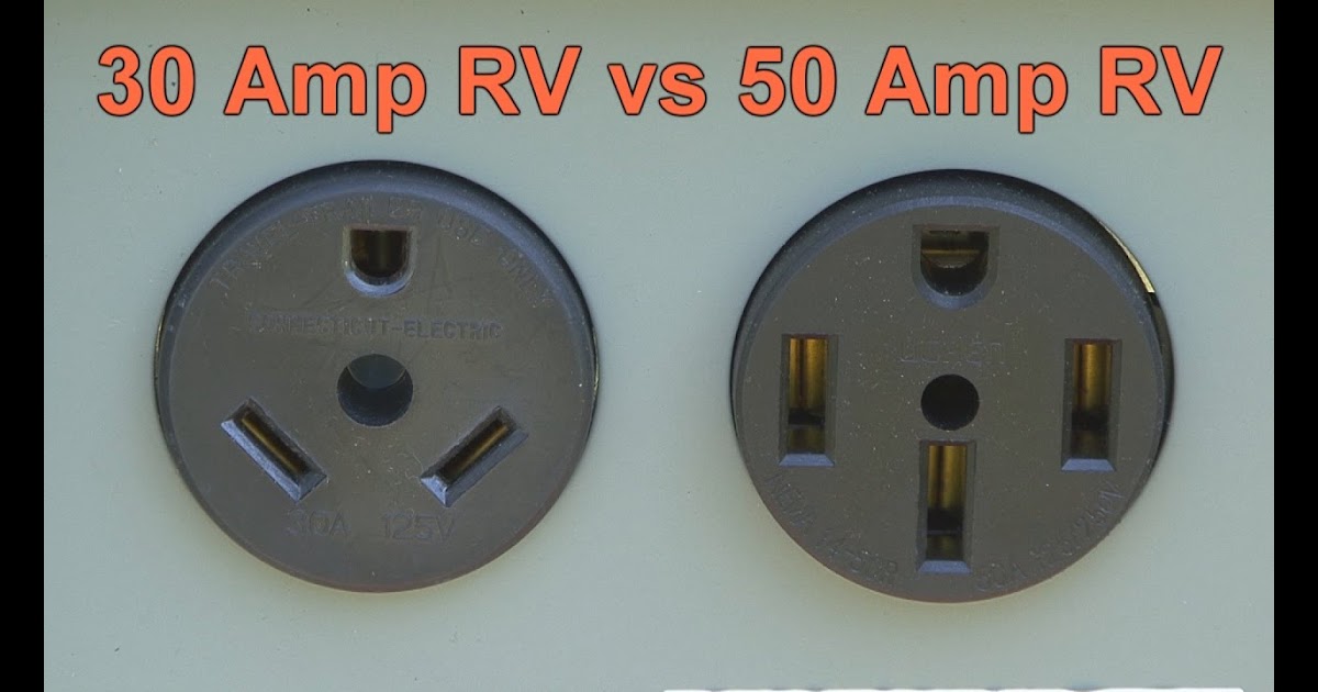
- Configuration: The NEMA 14-50 plug features a four-pronged configuration, consisting of two hot lines, a neutral line, and a ground line. This configuration allows for the delivery of both 120 and 240 volts to the RV’s electrical system.
- Amperage Rating: The NEMA 14-50 plug is rated for 50 amps, indicating its capacity to handle high electrical currents. This amperage rating is suitable for powering larger RVs with multiple appliances and systems.
- Voltage Compatibility: The NEMA 14-50 plug is compatible with both 120-volt and 240-volt electrical systems. This versatility allows RVs to connect to a wider range of power sources, including RV parks, campgrounds, and even residential outlets.
- Safety Features: The NEMA 14-50 plug incorporates safety features such as grounding, which provides a safe path for electrical faults. Additionally, the plug’s locking mechanism ensures a secure connection, preventing accidental disconnections.
Understanding the plug type is essential for selecting the appropriate plug and receptacle for RV electrical connections. Using an incompatible plug type can lead to electrical hazards, damage to equipment, and potential safety risks. The NEMA 14-50 plug is widely recognized and accepted in the RV industry, ensuring compatibility with various RV electrical systems and external power sources.
Wire Gauge
Within the context of “Travel Trailer 50 Amp RV Plug Wiring Diagram,” the wire gauge holds critical importance as it directly influences the safe and efficient operation of the RV’s electrical system. Wire gauge refers to the thickness of the wires used in the plug, which is inversely proportional to their resistance. Thicker wires have lower resistance, allowing for better current flow and reduced voltage drop.
The selection of appropriate wire gauge is crucial for ensuring that the plug can handle the high electrical currents associated with 50-amp RV connections. Undersized wires can lead to overheating, voltage loss, and potential fire hazards. Conversely, oversized wires, while less common, can add unnecessary weight and cost to the wiring system.
Real-life examples of wire gauge considerations in “Travel Trailer 50 Amp RV Plug Wiring Diagram” include:
- The hot lines of a 50-amp RV plug typically use 6-gauge wire, which can safely carry up to 55 amps of current.
- The neutral line of a 50-amp RV plug uses 4-gauge wire, which can handle the combined return current from both hot lines.
- The ground line of a 50-amp RV plug uses 8-gauge wire, which provides a low-resistance path for electrical faults.
Understanding the relationship between wire gauge and “Travel Trailer 50 Amp RV Plug Wiring Diagram” enables informed decision-making when selecting and installing RV electrical components. Proper wire gauge selection ensures optimal current flow, minimizes voltage drop, and enhances the safety and reliability of the RV’s electrical system.
Color Coding
Within the context of “Travel Trailer 50 Amp RV Plug Wiring Diagram,” color coding plays a vital role in ensuring accurate wire identification and maintaining electrical safety. The standardized use of colors for different types of wires simplifies the wiring process, reduces the risk of errors, and facilitates troubleshooting.
- Hot Lines: Typically identified with the colors black and red, the hot lines carry the electrical current from the power source to the RV’s electrical system.
- Neutral Line: Represented by the color white, the neutral line provides a reference point for the electrical circuit and completes the path for current flow.
- Ground Line: The ground line, identified by the color green, provides a safety path for electrical faults and helps protect against electrical shocks.
- Bonding Wire: In some cases, a bare copper wire may be used as a bonding wire, which connects the RV’s frame to the electrical system to ensure proper grounding.
Adhering to color coding standards is crucial for both the initial installation and subsequent maintenance of RV electrical systems. Proper wire identification minimizes the risk of accidental misconnections, ensuring that the electrical system functions safely and efficiently. Additionally, color coding facilitates troubleshooting by allowing electricians to quickly identify and isolate faulty wires or components.
Grounding
In the context of “Travel Trailer 50 Amp RV Plug Wiring Diagram,” grounding plays a critical role in ensuring the safety and proper functioning of the RV’s electrical system. Grounding provides a low-resistance path for electrical faults, protecting against electrical shocks, fires, and damage to electrical components.
The grounding line in a 50-amp RV plug wiring diagram is typically identified by the color green. It is connected to the RV’s frame and to the ground rod at the RV’s campsite. This connection creates a path for any stray electrical currents to flow safely into the ground, preventing them from traveling through the RV’s electrical system or causing harm to occupants.
A real-life example of the importance of grounding in “Travel Trailer 50 Amp RV Plug Wiring Diagram” is the protection it provides against lightning strikes. Lightning strikes can induce high-voltage surges into the RV’s electrical system. Without proper grounding, these surges could damage sensitive electrical components or even start a fire. The grounding line provides a safe path for these surges to flow into the ground, protecting the RV and its occupants.
Understanding the role of grounding in “Travel Trailer 50 Amp RV Plug Wiring Diagram” is essential for ensuring the safe and reliable operation of RV electrical systems. Proper grounding practices help prevent electrical hazards, protect against damage to electrical components, and provide peace of mind for RV owners and occupants.
Safety Features
Within the realm of “Travel Trailer 50 Amp RV Plug Wiring Diagram,” safety features play a pivotal role in ensuring the protection of both the electrical system and the occupants of the RV. These features encompass measures like surge protection and weatherproofing, safeguarding against potential hazards and adverse environmental conditions.
-
Surge Protection:
Surge protection devices shield the RV’s electrical system from sudden and potentially damaging voltage spikes. These spikes can arise from external sources like lightning strikes or internal faults. Surge protectors divert excess voltage away from sensitive components, preventing damage and ensuring the longevity of the electrical system.
-
Weatherproofing:
Weatherproofing measures protect the plug and wiring from the elements. Moisture, dust, and extreme temperatures can corrode electrical connections and compromise the safety of the system. Weatherproofing features like rubber gaskets and sealed enclosures prevent moisture ingress and ensure reliable operation in various weather conditions.
-
Polarity Indicator:
A polarity indicator helps ensure proper wiring and prevent accidental reversal of the hot and neutral wires. Incorrect polarity can lead to electrical hazards and damage to appliances. The indicator provides a visual cue to verify correct wiring, enhancing safety and preventing potential issues.
-
Strain Relief:
Strain relief mechanisms prevent excessive bending or pulling on the electrical cord, reducing the risk of damage to the wires and connections. They provide support and reinforcement at the point where the cord enters the plug, ensuring a secure and reliable connection.
These safety features are crucial components of “Travel Trailer 50 Amp RV Plug Wiring Diagram,” contributing to the overall safety, reliability, and durability of the RV’s electrical system. By incorporating these measures, RV owners can enjoy peace of mind knowing that their electrical system is protected against potential hazards and environmental factors.


Related Posts


