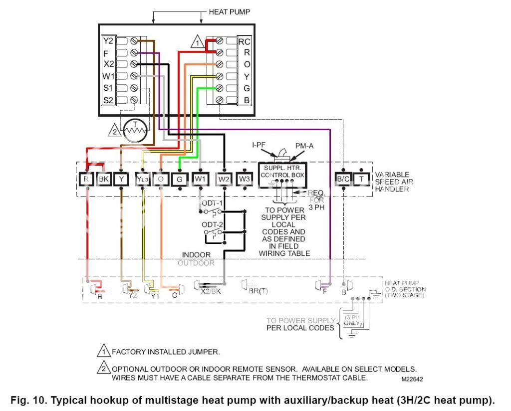
Trane Air Handler Wiring Diagram: A Trane air handler wiring diagram visually depicts the electrical connections and pathways within a Trane air handler, providing technicians with a detailed guide for proper installation, troubleshooting, and maintenance.
This diagram specifies the wiring of components like the blower motor, compressor, control board, and thermostat to ensure proper system operation. It guides technicians in connecting the electrical supply and components according to manufacturer specifications, promoting safety and efficiency.
Such diagrams have played a crucial role in the advancements of HVAC systems, enabling accurate wiring and eliminating electrical hazards. As the industry continues to evolve, these diagrams will remain an essential tool for technicians, ensuring the optimal performance of air handlers and maintaining indoor air quality.
Trane air handler wiring diagrams are crucial for the proper installation, maintenance, and troubleshooting of Trane air handlers. Understanding the essential aspects of these diagrams is paramount for HVAC technicians and professionals. Here are eight key aspects to consider:
- Electrical Safety: Diagrams ensure proper wiring, minimizing electrical hazards.
- Component Identification: They provide a visual guide to identify and locate components.
- Troubleshooting: Diagrams assist in diagnosing and resolving system malfunctions.
- Installation Guide: They offer step-by-step instructions for installing the air handler.
- Maintenance Schedule: Diagrams can include maintenance schedules to ensure optimal performance.
- Code Compliance: Diagrams help ensure compliance with electrical codes and standards.
- Warranty Validation: Proper wiring as per diagrams is often required for warranty claims.
- Efficiency Optimization: Diagrams guide technicians in optimizing system efficiency through proper wiring.
These aspects underscore the importance of Trane air handler wiring diagrams in ensuring the safety, reliability, and efficiency of HVAC systems. They provide a comprehensive roadmap for technicians, enabling them to work with precision and confidence.
Electrical Safety
In the context of Trane air handler wiring diagrams, electrical safety is of paramount importance. These diagrams provide precise instructions for wiring electrical components, minimizing the risk of electrical hazards and accidents.
- Grounding: Diagrams ensure proper grounding of the air handler, preventing electrical shocks and protecting against electrical faults.
- Circuit Protection: Diagrams specify the correct circuit breakers or fuses to use for each circuit, preventing overloads and potential fires.
- Wire Sizing: Diagrams indicate the appropriate wire gauge for each connection, ensuring that wires can safely handle the electrical current without overheating.
- Component Compatibility: Diagrams ensure compatibility between electrical components, preventing damage or malfunctions due to incorrect wiring.
Overall, Trane air handler wiring diagrams serve as a crucial tool for maintaining electrical safety in HVAC systems. By providing clear and accurate wiring instructions, these diagrams empower technicians to perform installations and repairs confidently, minimizing electrical hazards and ensuring the longevity and reliability of the system.
Component Identification
Trane air handler wiring diagrams serve as a comprehensive guide for technicians, enabling them to identify and locate components within the air handler. This aspect is particularly crucial for troubleshooting, maintenance, and repair tasks.
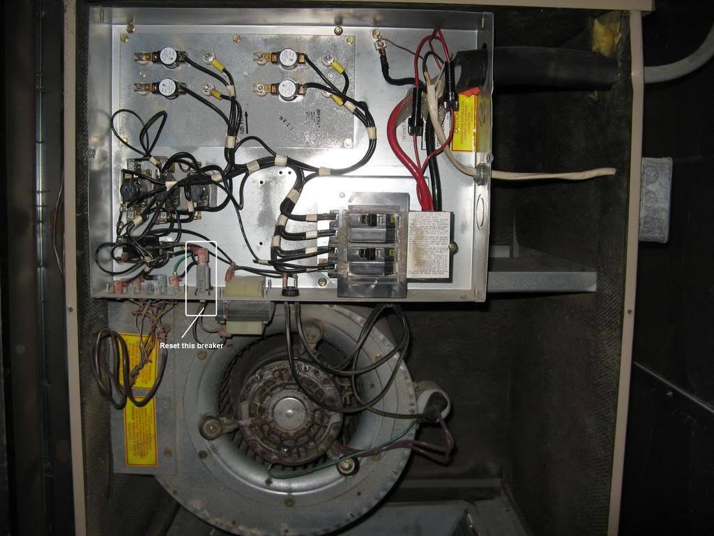
The diagrams provide a detailed visual representation of the air handler’s internal components, including the blower motor, compressor, control board, and electrical terminals. Each component is clearly labeled, allowing technicians to quickly identify and locate the necessary parts for servicing or replacement.
For instance, if a technician encounters an issue with the blower motor, the wiring diagram will guide them to the exact location of the motor within the air handler. This eliminates guesswork and saves valuable time during troubleshooting and repair processes.
Furthermore, the component identification aspect of Trane air handler wiring diagrams is essential for ensuring proper wiring and connections. By accurately identifying and locating components, technicians can ensure that electrical wires are connected to the correct terminals, preventing malfunctions and potential hazards.
In summary, the component identification aspect of Trane air handler wiring diagrams is a critical element that empowers technicians to efficiently troubleshoot, maintain, and repair air handlers. By providing a clear visual guide to identify and locate components, these diagrams enhance the safety, reliability, and performance of HVAC systems.
Troubleshooting
In the context of Trane air handler wiring diagrams, their role in troubleshooting is indispensable. These diagrams provide a visual representation of the electrical connections and components within the air handler, enabling technicians to quickly identify and resolve system malfunctions.
When a system malfunction occurs, technicians can refer to the wiring diagram to trace the electrical connections and identify the affected component. This systematic approach saves valuable time and effort compared to randomly checking components or relying solely on experience. For instance, if an air handler is not blowing air, the wiring diagram can guide the technician to check the power supply, blower motor, and control board, helping to pinpoint the root cause of the issue.
Furthermore, Trane air handler wiring diagrams assist in troubleshooting by providing insights into the system’s operation. By understanding the electrical connections and component interactions, technicians can make informed decisions about the appropriate repair or replacement strategies. This knowledge reduces guesswork and helps avoid unnecessary part replacements, saving time and resources.
In summary, Trane air handler wiring diagrams play a critical role in troubleshooting by providing a visual guide to the system’s electrical connections and components. Their use enables technicians to diagnose and resolve system malfunctions efficiently, minimizing downtime and ensuring the optimal performance of HVAC systems.
Installation Guide
The installation guide is a critical component of the Trane Air Handler Wiring Diagram. It provides detailed, step-by-step instructions on how to properly install the air handler, ensuring its safe and efficient operation.
The wiring diagram assumes that the air handler has been correctly installed according to the installation guide. Improper installation can lead to electrical hazards, system malfunctions, and reduced performance. Therefore, it is crucial for technicians to thoroughly follow the installation guide before attempting to wire the air handler.
For instance, the installation guide will specify the required clearances around the air handler, the mounting method, and the electrical connections to the power supply. By adhering to these instructions, technicians can ensure that the air handler is properly secured, has adequate airflow, and is electrically safe.
In summary, the installation guide and the Trane Air Handler Wiring Diagram are closely related. The installation guide provides the foundation for proper air handler installation, while the wiring diagram guides the electrical connections. By following both documents carefully, technicians can ensure a safe and efficient HVAC system.
Maintenance Schedule
Trane Air Handler Wiring Diagrams often include maintenance schedules to provide technicians with a comprehensive guide for maintaining the air handler and ensuring optimal performance. These schedules specify the recommended maintenance tasks, their frequency, and the necessary steps to perform them.
A well-maintained air handler operates more efficiently, consumes less energy, and experiences fewer breakdowns. Regular maintenance tasks include cleaning the air filter, inspecting the blower motor, and checking the electrical connections. By adhering to the maintenance schedule, technicians can identify potential issues early on and address them before they become major problems.
For instance, the maintenance schedule may recommend cleaning the air filter every month and inspecting the blower motor every six months. This helps ensure that the air handler operates at peak efficiency, preventing dirt and debris from accumulating and causing airflow problems.
The maintenance schedule included in the Trane Air Handler Wiring Diagram serves as a valuable tool for technicians and homeowners alike. By following the recommended maintenance tasks, they can prolong the lifespan of the air handler, improve its performance, and reduce the risk of costly repairs.
Code Compliance
In the context of Trane Air Handler Wiring Diagrams, code compliance is a crucial aspect that ensures the electrical safety and integrity of the HVAC system. These diagrams play a vital role in guiding technicians to wire the air handler in accordance with established electrical codes and standards.
Electrical codes and standards, such as the National Electrical Code (NEC) in the United States, provide a set of regulations and guidelines for the safe installation and operation of electrical systems. These codes aim to minimize the risk of electrical hazards, fires, and accidents. Trane Air Handler Wiring Diagrams incorporate these codes and standards into their design, ensuring that the wiring complies with the required safety measures.
For instance, the wiring diagram will specify the proper wire sizes, types, and connections to meet the electrical code requirements. It will also indicate the correct grounding and bonding methods to ensure the safety of the system. By following the instructions provided in the wiring diagram, technicians can confidently install the air handler, knowing that it adheres to the applicable electrical codes and standards.
Moreover, code compliance is not only crucial for safety but also for obtaining permits and passing inspections. Many local authorities require electrical installations to be inspected and approved before they can be operated. A Trane Air Handler Wiring Diagram that demonstrates code compliance can expedite this process, as it provides evidence that the installation meets the required safety standards.
In summary, Trane Air Handler Wiring Diagrams serve as a valuable tool for ensuring code compliance in HVAC systems. By providing detailed instructions that adhere to electrical codes and standards, these diagrams empower technicians to install and maintain air handlers safely and efficiently, minimizing electrical hazards and ensuring the longevity of the system.
Warranty Validation
Within the context of “Trane Air Handler Wiring Diagram”, warranty validation holds great significance. Proper wiring, as outlined in these diagrams, is often a crucial requirement for manufacturers to honor warranty claims. Failing to adhere to the specified wiring instructions can potentially void the warranty, leaving homeowners or contractors responsible for repair costs.
- Specified Components: Trane Air Handler Wiring Diagrams provide precise instructions on the types and specifications of electrical components that must be used. Using incompatible or non-approved components can lead to system malfunctions and void the warranty.
- Wiring Methods: The diagrams detail the proper techniques for connecting wires, including the use of appropriate wire gauges, connectors, and grounding methods. Incorrect wiring practices can compromise the safety and performance of the air handler, potentially invalidating the warranty.
- Professional Installation: Many manufacturers require that air handlers be installed by licensed HVAC technicians to ensure proper wiring and system operation. Attempting DIY installations without proper training or certification can result in warranty denial.
- Proof of Wiring: In the event of a warranty claim, manufacturers may request proof that the air handler was wired according to the provided diagram. This can be demonstrated through documentation, photographs, or inspection by a qualified technician.
Warranty validation through proper wiring is not merely a technicality but a measure to ensure the safety, reliability, and longevity of Trane air handlers. By adhering to the wiring diagrams, homeowners and contractors can protect their investment, minimize the risk of system failures, and maintain optimal indoor air quality.
Efficiency Optimization
Within the context of “Trane Air Handler Wiring Diagram”, efficiency optimization plays a pivotal role in maximizing the performance and energy efficiency of Trane air handlers. The wiring diagrams provide detailed instructions on how to properly connect electrical components to ensure optimal system operation and minimize energy consumption.
- Component Compatibility: The diagrams specify compatible components that work together seamlessly, reducing energy losses and improving overall system efficiency. Mismatched components can lead to inefficiencies and premature system failures.
- Optimized Wiring Techniques: The diagrams outline specific wiring techniques, such as proper wire sizing and routing, that minimize electrical resistance and heat generation. This results in reduced energy waste and improved system longevity.
- Control System Integration: The diagrams guide the integration of advanced control systems that monitor and adjust system operation based on real-time conditions. These systems optimize energy consumption by matching the air handler’s output to the actual heating or cooling needs of the space.
- Maintenance and Troubleshooting: Proper wiring as per the diagrams facilitates regular maintenance and troubleshooting tasks. Accurate wiring simplifies the identification and replacement of faulty components, reducing downtime and ensuring peak system performance.
By following the efficiency optimization guidelines in Trane Air Handler Wiring Diagrams, technicians can ensure that the air handler operates at its optimal efficiency, leading to lower energy bills, reduced environmental impact, and a more comfortable indoor environment.


Related Posts


