A trailer tail light wiring diagram provides detailed instructions on how to connect the electrical wires of a vehicle to the tail lights of a trailer. It outlines which wires should be connected and how to ensure proper functioning of the trailer’s lighting system.
Understanding and following a trailer tail light wiring diagram is crucial for the safe and legal operation of towing a trailer. Benefits include increased visibility, proper circuit protection, and compliance with road regulations. Historically, trailer lighting systems evolved from simple incandescent bulbs to modern LED arrays, increasing durability and visibility.
This article will delve further into the complexities of trailer tail light wiring, addressing advanced topics such as multiplexing, CAN bus systems, and troubleshooting techniques. It will provide comprehensive information for professionals, enthusiasts, and anyone interested in understanding and maintaining trailer lighting.
Trailer tail light wiring diagrams are crucial for ensuring the safe and legal operation of trailers by providing detailed instructions on how to connect the electrical wires of a vehicle to the tail lights of a trailer. Understanding and following a trailer tail light wiring diagram is essential, and key aspects to consider include:
- Wiring Type: Different types of wiring, such as stranded or solid core, may be used.
- Wire Gauge: The thickness of the wire, measured in gauge, determines its current-carrying capacity.
- Circuit Protection: Fuses or circuit breakers protect the wiring from overcurrent conditions.
- Grounding: Proper grounding ensures a complete electrical circuit and prevents electrical faults.
- Connector Types: Various connector types, such as flat four or round seven, are used to connect the vehicle and trailer.
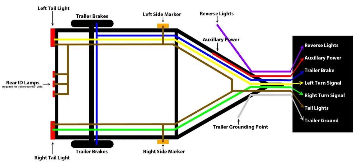
- Lighting Functions: The diagram specifies the wiring for tail lights, brake lights, turn signals, and other lighting functions.
- Trailer Brakes: If the trailer has electric brakes, the wiring diagram includes instructions for connecting the brake controller.
- Multiple Trailers: Diagrams for towing multiple trailers outline how to connect the electrical systems.
- Troubleshooting: The diagram can assist in identifying and resolving electrical issues with the trailer lights.
- Legal Compliance: Following the wiring diagram ensures compliance with safety regulations and vehicle codes.
These aspects are interconnected and essential for a properly functioning trailer tail light system. Understanding them enables individuals to make informed decisions about trailer wiring, ensuring the safety and reliability of their towing setup.
Wiring Type
In the context of trailer tail light wiring diagrams, the selection of wiring type is crucial for ensuring a reliable and safe electrical connection. Stranded wire, composed of multiple thin strands, offers flexibility and resistance to breakage, making it suitable for applications where movement and vibration are present. Solid core wire, on the other hand, consists of a single solid conductor and is more rigid, providing better current-carrying capacity. The choice between these two types depends on the specific requirements of the trailer lighting system.
Trailer tail light wiring diagrams specify the appropriate wire gauge, insulation type, and length for each connection. Understanding the characteristics of stranded and solid core wiring allows individuals to make informed decisions when selecting and installing the electrical components. For instance, stranded wire may be preferred for connecting tail lights that experience movement due to trailer sway, while solid core wire could be used for power lines requiring higher current capacity.
By providing detailed instructions on the type of wiring to be used, trailer tail light wiring diagrams empower individuals to create secure and functional electrical connections. This understanding contributes to the overall safety and reliability of the towing system, ensuring that trailer lights operate correctly and meet regulatory requirements.
Wire Gauge
In the context of trailer tail light wiring diagrams, wire gauge plays a critical role in ensuring the safe and reliable operation of the trailer lighting system. The thickness of the wire, measured in gauge, directly affects its ability to carry electrical current. Thicker wires, denoted by a lower gauge number, have a greater capacity to conduct current compared to thinner wires with higher gauge numbers.
Trailer tail light wiring diagrams specify the appropriate wire gauge for each connection based on the current draw of the lighting components. For instance, heavier gauge wire is used for high-power applications such as brake lights, while thinner gauge wire may suffice for low-power applications like side marker lights.
Understanding the relationship between wire gauge and current-carrying capacity is essential for proper trailer wiring. Using wire that is too thin for the intended application can lead to overheating, voltage drop, and potential electrical hazards. Conversely, using wire that is thicker than necessary can be wasteful and increase the overall cost of the wiring system.
By providing precise guidance on wire gauge selection, trailer tail light wiring diagrams empower individuals to create safe and efficient electrical connections. This understanding contributes to the overall reliability of the towing system, ensuring that trailer lights function correctly and meet regulatory requirements.
Circuit Protection
Within the context of Trailer Tail Light Wiring Diagrams, circuit protection plays a crucial role in safeguarding the electrical system from potential hazards. Fuses or circuit breakers act as essential components in preventing overcurrent conditions, which can lead to damage to the wiring, components, and even the trailer itself.
- Fuse Protection: Fuses are sacrificial devices that interrupt the circuit when the current exceeds a predetermined level. They protect the wiring by melting and breaking the circuit, preventing further damage. Trailer tail light wiring diagrams specify the appropriate fuse rating for each circuit, ensuring proper protection.
- Circuit Breaker Protection: Circuit breakers are resettable devices that automatically interrupt the circuit when an overcurrent condition occurs. They offer the advantage of being reusable, eliminating the need for fuse replacement. Wiring diagrams indicate the type and location of circuit breakers used in the trailer lighting system.
- Ground Fault Protection: Ground fault circuit interrupters (GFCIs) are specialized devices that protect against electrical shock by detecting imbalances between the current flowing in the hot and neutral wires. They are particularly important in outdoor environments where moisture can create a risk of electrical hazards.
- Surge Protection: Surge protectors are devices that safeguard the electrical system from voltage spikes and transients. They divert excess voltage away from sensitive components, preventing damage to the trailer lighting system.
Understanding and incorporating circuit protection measures as outlined in trailer tail light wiring diagrams is crucial for the safe and reliable operation of the trailer lighting system. These protective devices ensure that electrical faults are contained, preventing catastrophic failures and potential hazards.
Grounding
Within the context of Trailer Tail Light Wiring Diagrams, grounding plays a critical role in establishing a complete electrical circuit and preventing electrical faults. Grounding provides a low-resistance path for electrical current to flow back to the source, completing the circuit and ensuring proper functioning of the trailer lighting system.
Trailer tail light wiring diagrams specify the grounding points for each component, typically connecting to the trailer frame or a dedicated grounding wire. This ensures that all electrical components have a common reference point, preventing voltage imbalances and reducing the risk of electrical shorts or other hazards.
Proper grounding is essential for the following reasons:
- Circuit Completion: Grounding provides a complete path for electrical current to flow, allowing the lighting system to function correctly.
- Voltage Regulation: A proper ground ensures stable voltage levels throughout the system, preventing voltage fluctuations that can damage sensitive components.
- Electrical Safety: Grounding diverts stray electrical currents away from the trailer and its occupants, reducing the risk of electrical shocks or fires.
Understanding and implementing proper grounding as outlined in trailer tail light wiring diagrams is crucial for the safe and reliable operation of the trailer lighting system. By ensuring a complete electrical circuit and preventing electrical faults, proper grounding contributes to the overall functionality and safety of the trailer.
Connector Types
Within the context of Trailer Tail Light Wiring Diagrams, connector types play a crucial role in establishing a secure and reliable electrical connection between the vehicle and the trailer. These connectors ensure the proper flow of electrical signals for lighting functions, brakes, and other essential systems.
- Pin Configuration: Trailer connectors come in different pin configurations, each with a specific number and arrangement of pins. Common configurations include flat four, round seven, and Deutsch connectors, each designed for specific applications and vehicle types.
- Wiring Compatibility: The connector type must match the wiring configuration of the vehicle and the trailer. Proper wiring ensures that the correct electrical signals are transmitted, preventing malfunctions or damage to the lighting system.
- Durability and Weather Resistance: Trailer connectors are exposed to harsh outdoor conditions, including moisture, dirt, and vibration. Durable connectors with weather-resistant materials ensure reliable performance and longevity.
- Safety Features: Some connector types incorporate safety features such as locking mechanisms or color-coded pins to prevent accidental disconnections or incorrect wiring.
Understanding and selecting the appropriate connector type is crucial for the safe and reliable operation of the trailer lighting system. Proper connections prevent electrical faults, ensure proper signal transmission, and maintain compliance with industry standards and regulations.
Lighting Functions
Within the context of Trailer Tail Light Wiring Diagrams, the specification of lighting functions is a critical component, as it provides a comprehensive overview of the electrical connections required for each lighting function on the trailer. This detailed information ensures that the trailer’s lighting system operates correctly, ensuring visibility, safety, and compliance with regulations.
The wiring diagram outlines the specific wiring connections for each lighting function, typically including tail lights, brake lights, turn signals, side markers, and license plate lights. By following the diagram’s instructions, individuals can properly connect the electrical wires to the corresponding lighting components, ensuring that each function operates as intended.
For instance, the diagram specifies the wiring for the tail lights, which are essential for providing rear visibility during nighttime or low-visibility conditions. Proper wiring ensures that the tail lights illuminate when the vehicle’s headlights are turned on, indicating the trailer’s presence to other drivers.
Furthermore, the diagram provides instructions for connecting the brake lights, which are crucial for signaling braking intentions to following vehicles. By understanding the wiring for the brake lights, individuals can ensure that they function correctly, alerting other drivers and preventing potential accidents.
In summary, the specification of lighting functions within Trailer Tail Light Wiring Diagrams is essential for the proper installation and operation of the trailer’s lighting system. By providing detailed instructions for each lighting function, these diagrams empower individuals to create safe and compliant trailer lighting setups, contributing to overall road safety.
Trailer Brakes
Within the context of Trailer Tail Light Wiring Diagrams, the inclusion of instructions for connecting the brake controller, if applicable, is of critical importance. This is because the proper functioning of electric trailer brakes relies on a properly installed and connected brake controller within the towing vehicle.
The brake controller acts as an intermediary between the vehicle’s braking system and the electric brakes on the trailer. When the driver applies the brakes in the towing vehicle, the brake controller sends a signal to the electric brakes on the trailer, actuating them and providing additional stopping power. Without a properly connected brake controller, the electric brakes on the trailer will not function, potentially leading to reduced braking efficiency and increased stopping distances.
Trailer Tail Light Wiring Diagrams provide detailed instructions on how to connect the brake controller to the vehicle’s electrical system and the trailer’s brake system. These instructions typically include specifying the appropriate wiring connections, fuse or circuit breaker ratings, and any additional components or modules required for the brake controller’s operation.
Understanding and following the instructions for connecting the brake controller is essential for ensuring the safe and effective operation of the trailer’s braking system. By properly connecting the brake controller as outlined in the Trailer Tail Light Wiring Diagram, individuals can ensure that the electric brakes on the trailer are properly activated when the vehicle’s brakes are applied, contributing to overall braking efficiency and road safety.
Multiple Trailers
Within the context of Trailer Tail Light Wiring Diagrams, the inclusion of instructions for connecting multiple trailers is of paramount importance, as it enables the safe and proper operation of multiple trailers towed behind a single vehicle. These diagrams provide detailed guidance on how to connect the electrical systems of each trailer to the towing vehicle, ensuring that all lighting functions, brakes, and other essential systems operate correctly.
- Trailer Brake Controllers: When towing multiple trailers, additional brake controllers may be required to manage the braking systems of each trailer. Wiring diagrams specify the proper installation and connection of these controllers, ensuring that all trailers brake effectively.
- Electrical Load Distribution: Towing multiple trailers increases the electrical load on the towing vehicle. Wiring diagrams provide instructions on how to distribute the electrical load evenly, preventing overloading and potential electrical issues.
- Lighting Synchronization: When towing multiple trailers, it is important to ensure that the lighting systems of all trailers are synchronized. Wiring diagrams specify how to connect the lighting systems to achieve this synchronization, ensuring proper visibility and signaling.
- Compliance with Regulations: Towing multiple trailers may be subject to specific regulations and requirements. Wiring diagrams help ensure that the electrical connections comply with these regulations, promoting safety and avoiding legal issues.
Understanding and following the instructions for connecting multiple trailers as outlined in Trailer Tail Light Wiring Diagrams is essential for the safe and efficient operation of multiple trailers. By properly connecting the electrical systems, individuals can ensure that all trailers are properly equipped and functioning, contributing to overall road safety and compliance with regulations.
Troubleshooting
Troubleshooting electrical issues with trailer lights is a critical aspect of Trailer Tail Light Wiring Diagrams. These diagrams provide a systematic approach to identifying and resolving electrical faults, ensuring the proper functioning of the trailer’s lighting system.
The troubleshooting section of a Trailer Tail Light Wiring Diagram typically includes step-by-step instructions on how to diagnose and fix common electrical problems. These instructions may involve testing voltage, checking connections, and identifying faulty components. By following the troubleshooting guide, individuals can pinpoint the source of the electrical issue and implement the necessary repairs or replacements.
Real-life examples of troubleshooting electrical issues using a Trailer Tail Light Wiring Diagram include:
- Identifying a blown fuse or tripped circuit breaker that has interrupted the power supply to the trailer lights.
- Locating a loose or corroded connection that is preventing the electrical current from flowing properly.
- Diagnosing a faulty light bulb or LED module that has stopped functioning.
Understanding how to troubleshoot electrical issues using a Trailer Tail Light Wiring Diagram is essential for maintaining a safe and reliable trailer lighting system. By being able to identify and resolve electrical problems, individuals can ensure that their trailers are properly equipped and functioning, contributing to overall road safety and compliance with regulations.
Legal Compliance
Adhering to the guidelines outlined in Trailer Tail Light Wiring Diagrams is crucial for ensuring legal compliance with established safety regulations and vehicle codes. These regulations are in place to promote road safety and minimize the risk of accidents, and proper trailer lighting is an essential aspect of maintaining compliance.
Trailer Tail Light Wiring Diagrams provide detailed instructions on how to connect the electrical system of a trailer to the towing vehicle, ensuring that all lighting functions operate correctly. Following these instructions helps ensure that the trailer’s lighting system meets the minimum visibility and signaling requirements mandated by law. This includes ensuring that the tail lights, brake lights, turn signals, side markers, and other lighting components are properly installed, connected, and functioning as intended.
By adhering to the wiring diagram and following established safety regulations, individuals can avoid potential legal penalties and contribute to overall road safety. Failure to comply with these regulations can result in fines, vehicle inspections, or even legal liability in the event of an accident.
Understanding the importance of legal compliance and the role of Trailer Tail Light Wiring Diagrams in achieving compliance is essential for responsible trailer operation. By following the guidelines outlined in these diagrams, individuals can ensure that their trailers are equipped with properly functioning lighting systems, promoting safety and compliance with established regulations.


Related Posts


