A trailer pigtail wiring diagram is a detailed illustration that represents the electrical connections between the tow vehicle and the trailer. For instance, a 7-way trailer wiring diagram explains how each of the seven electrical pins on the trailer connector connects to the corresponding wire colors on the tow vehicle’s wiring harness, allowing for proper functioning of lights, brakes, and other electrical components.
These diagrams are essential for ensuring the safety and proper operation of both the tow vehicle and the trailer. They also help troubleshoot and diagnose electrical issues, preventing potential hazards and breakdowns. A key historical development in trailer wiring was the standardization of color codes for different electrical functions, making it easier to identify and connect wires correctly.
In the following sections, we will delve into the different types of trailer pigtail wiring diagrams, their significance, and the best practices for using them. We will also explore advanced topics such as troubleshooting and customizing trailer wiring to meet specific needs.
Trailer pigtail wiring diagrams play a vital role in ensuring the safe and reliable connection between tow vehicles and trailers. Understanding their essential aspects is crucial for proper installation, maintenance, and troubleshooting.
- Connector Type: 4-way, 5-way, 6-way, 7-way, etc.
- Wire Gauge: Determines the current-carrying capacity of the wires.
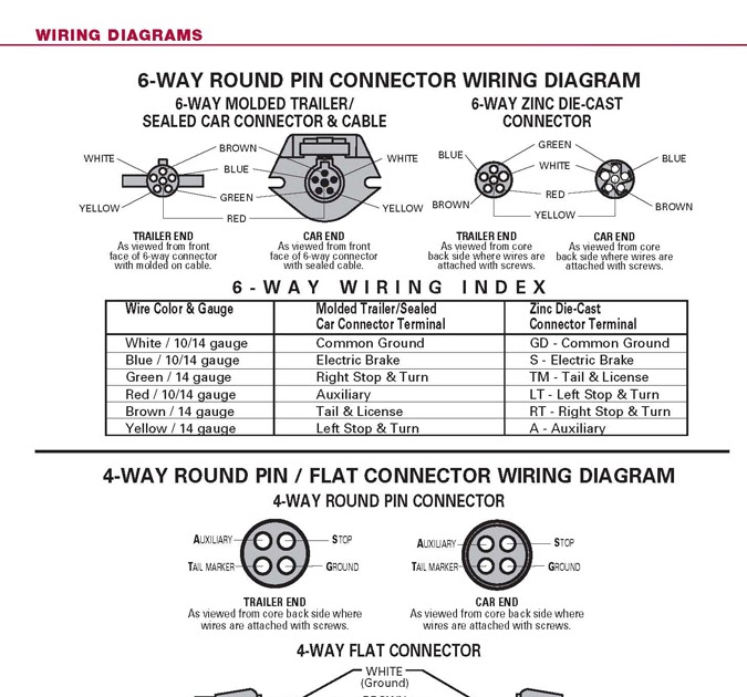
- Color Coding: Standardized colors for different electrical functions.
- Grounding: Proper grounding is essential for electrical safety.
- Circuit Protection: Fuses or circuit breakers protect against overloads.
- Testing: Verifying continuity and proper connections before use.
- Troubleshooting: Identifying and resolving electrical issues.
- Customization: Adapting wiring to specific trailer needs.
These aspects are interconnected and interdependent. For instance, the connector type determines the number of electrical circuits supported, while wire gauge and color coding ensure proper power distribution and identification. Understanding these aspects enables technicians and DIY enthusiasts to correctly install, maintain, and customize trailer wiring, ensuring the proper functioning of lights, brakes, and other electrical components.
Connector Type
The connector type is a critical component of a trailer pigtail wiring diagram, determining the number of electrical circuits supported and the corresponding functions they enable. Different types of connectors, such as 4-way, 5-way, 6-way, and 7-way, are designed to accommodate varying electrical needs and configurations of trailers.
For instance, a 4-way connector is commonly used for basic lighting functions like taillights, brake lights, and turn signals. As the number of circuits increases, so does the versatility and functionality of the trailer wiring. A 7-way connector, for example, supports additional circuits for electric brakes, reverse lights, and auxiliary power, enabling more complex electrical systems on larger trailers.
Understanding the relationship between connector type and trailer pigtail wiring diagram is essential for proper installation and troubleshooting. By selecting the appropriate connector type based on the trailer’s electrical requirements, technicians and DIY enthusiasts can ensure that all necessary functions are supported and that the wiring diagram accurately reflects the actual electrical connections.
In conclusion, the connector type plays a vital role in determining the capabilities of a trailer pigtail wiring diagram. Choosing the right connector type is crucial for ensuring compatibility with the trailer’s electrical system and maintaining safe and reliable operation.
Wire Gauge
In the context of trailer pigtail wiring diagrams, wire gauge plays a crucial role in ensuring the safe and efficient transmission of electrical current. The gauge of a wire refers to its cross-sectional area, which directly affects its ability to carry current without overheating or causing voltage drop.
- Conductor Material: Copper is the most common conductor material used in trailer wiring due to its excellent conductivity and durability.
- Wire Stranding: Wires can be composed of multiple strands of smaller wires, which provides increased flexibility and resistance to breakage.
- Insulation: The insulation surrounding the conductor protects it from short circuits and prevents current leakage.
- Amperage Rating: The amperage rating of a wire indicates the maximum amount of current it can safely carry without overheating.
Understanding the factors that influence wire gauge is essential for selecting the appropriate wiring for a specific trailer application. By considering the current draw of the trailer’s electrical components and the length of the wiring run, technicians and DIY enthusiasts can ensure that the wire gauge used in the trailer pigtail wiring diagram is adequate to handle the electrical load safely and efficiently.
Color Coding
In the realm of trailer pigtail wiring diagrams, color coding plays a pivotal role in ensuring efficient and error-free electrical connections between tow vehicles and trailers. Standardized colors are assigned to different electrical functions, enabling technicians and DIY enthusiasts to quickly identify and connect wires correctly, reducing the risk of mistakes and ensuring the proper functioning of lighting, braking, and other electrical components.
The importance of color coding cannot be overstated. Without standardized colors, trailer wiring diagrams would be much more complex and challenging to interpret, increasing the likelihood of errors during installation and maintenance. By adhering to color coding standards, technicians can quickly identify which wires correspond to each function, such as taillights, brake lights, turn signals, and electric brakes, ensuring that the electrical system is wired correctly and safely.
Real-life examples of color coding in trailer pigtail wiring diagrams are numerous. For instance, taillights are typically connected using brown wires, brake lights use red wires, and turn signals utilize yellow wires. These standardized colors are consistent across different trailer manufacturers and wiring harnesses, allowing technicians to easily identify and connect the correct wires, regardless of the specific trailer model or configuration. By following the color coding scheme, technicians can save time, reduce errors, and ensure the reliable operation of the trailer’s electrical system.
In conclusion, color coding is an essential component of trailer pigtail wiring diagrams, providing a standardized and intuitive method for connecting electrical wires. By adhering to color coding standards, technicians can ensure the accuracy and efficiency of trailer wiring installations, minimizing the risk of errors and ensuring the proper functioning of all electrical components. This standardized approach promotes safety, reliability, and ease of maintenance, making it a critical aspect of trailer pigtail wiring design.
Grounding
Within the realm of trailer pigtail wiring diagrams, grounding plays a critical role in ensuring electrical safety and preventing malfunctions. Grounding provides a low-resistance path for electrical current to flow back to the source, reducing the risk of electrical shocks, equipment damage, and fires.
- Chassis Ground: The trailer’s metal frame serves as the primary grounding point, connecting all electrical components to a common reference.
- Dedicated Ground Wire: In addition to the chassis ground, a dedicated ground wire is often used to provide a more reliable and consistent grounding path.
- Proper Connections: All electrical components must be properly connected to the grounding system to ensure effective grounding.
- Safety Feature: Grounding acts as a safety measure by diverting stray electrical currents away from sensitive components and preventing electrical hazards.
By understanding and adhering to proper grounding practices outlined in trailer pigtail wiring diagrams, technicians and DIY enthusiasts can ensure the safe and reliable operation of trailer electrical systems. Neglecting grounding can lead to electrical faults, malfunctions, and safety concerns, highlighting the critical importance of grounding in trailer wiring.
Circuit Protection
Circuit protection is an essential aspect of trailer pigtail wiring diagrams, ensuring the safety and reliability of the electrical system. Overloads, which occur when excessive current flows through a circuit, can lead to overheating, damage to electrical components, and even fires. Fuses and circuit breakers serve as protective devices, interrupting the electrical current when it exceeds a predetermined safe level, preventing potential hazards.
In trailer pigtail wiring diagrams, circuit protection is typically implemented using fuses or circuit breakers. Fuses are single-use devices that contain a thin wire designed to melt and break the circuit when the current exceeds the fuse’s rated amperage. Circuit breakers, on the other hand, are reusable devices that can be manually reset after they trip. Both fuses and circuit breakers are placed in strategic locations within the wiring diagram to protect specific circuits and components from overloads.
Real-life examples of circuit protection in trailer pigtail wiring diagrams include the use of fuses to protect the lighting circuits, and circuit breakers to protect the electric brake system. By incorporating these protective devices into the wiring diagram, technicians and DIY enthusiasts can ensure that the trailer’s electrical system is protected against overloads, preventing potential damage or accidents.
Understanding the connection between circuit protection and trailer pigtail wiring diagrams is crucial for the safe and reliable operation of trailers. By adhering to proper circuit protection practices, technicians and DIY enthusiasts can minimize the risk of electrical hazards, ensure the longevity of electrical components, and maintain the overall integrity of the trailer’s electrical system.
Testing
In the context of “Trailer Pigtail Wiring Diagram”, testing plays a crucial role in ensuring the safety, reliability, and proper functioning of the trailer’s electrical system. Before connecting the trailer to a tow vehicle and putting it into operation, it is essential to verify the continuity and correctness of all electrical connections to avoid potential hazards, malfunctions, or damage to equipment.
- Continuity Testing: Using a multimeter or continuity tester, technicians check if there is a complete electrical path between different points in the circuit, ensuring that current can flow without interruption.
- Grounding Verification: Testing the continuity between the trailer’s frame and the ground wire ensures that the electrical system is properly grounded, providing a safe path for current to return to the source, preventing electrical shocks and component damage.
- Polarity Confirmation: For certain electrical components, such as LED lights, it is crucial to verify the correct polarity of the connections. Reversing the polarity can lead to malfunction or damage to the component.
- Load Testing: Applying a load to the circuit, such as connecting a light bulb or other electrical device, helps identify potential issues with the wiring or components under real-world conditions, ensuring that they can handle the intended electrical load.
By incorporating these testing procedures into the “Trailer Pigtail Wiring Diagram” and diligently following them, technicians and DIY enthusiasts can increase the likelihood of a safe and reliable electrical system for their trailers. These tests help identify and correct any issues before connecting the trailer to a power source, preventing potential hazards, ensuring optimal performance, and extending the lifespan of the electrical components.
Troubleshooting
Within the context of “Trailer Pigtail Wiring Diagram”, troubleshooting encompasses the systematic identification and resolution of electrical problems. It ensures the safety, reliability, and optimal performance of the trailer’s electrical system.
- Identifying Symptoms: Recognizing signs of electrical issues, such as malfunctioning lights, inoperative brakes, or intermittent power supply, is crucial for timely troubleshooting.
- Isolation of Problem: Isolating the affected circuit or component through systematic testing helps narrow down the root cause of the issue, reducing troubleshooting time and effort.
- Inspection and Repair: Thoroughly inspecting the wiring, connections, and components allows for identifying loose connections, damaged wires, or faulty components that need repair or replacement.
- Verification of Resolution: After implementing repairs or replacements, testing the affected circuit or component verifies the successful resolution of the electrical issue, ensuring the system is functioning correctly.
By understanding and applying these troubleshooting techniques, technicians and DIY enthusiasts can effectively diagnose and resolve electrical problems with their trailer’s wiring system, ensuring a safe, reliable, and trouble-free operation on the road.
Customization
In the realm of “Trailer Pigtail Wiring Diagram”, customization plays a pivotal role in adapting the electrical system to the specific needs and configurations of different trailers. This involves modifying or extending the wiring harness to accommodate unique lighting arrangements, additional electrical components, or specialized equipment.
Customization becomes a critical component of “Trailer Pigtail Wiring Diagram” when standard wiring configurations do not meet the specific requirements of a particular trailer. For instance, a trailer designed for hauling heavy machinery may require a more robust electrical system with higher amperage wiring and additional circuits to power specialized equipment. In such cases, the wiring diagram must be customized to ensure the electrical system can safely and efficiently handle the increased electrical load.
Real-life examples of “Customization: Adapting wiring to specific trailer needs” within “Trailer Pigtail Wiring Diagram” include:
Adding a backup camera system to a trailer requires extending the wiring harness to accommodate the camera and monitor. Installing additional lighting, such as side marker lights or underbody lighting, necessitates modifying the wiring diagram to incorporate these additional circuits. Upgrading the electrical system to support a solar power setup involves customizing the wiring diagram to integrate the solar panels, charge controller, and battery.
Understanding the connection between “Customization: Adapting wiring to specific trailer needs” and “Trailer Pigtail Wiring Diagram” is crucial for ensuring the electrical system is tailored to the specific requirements of the trailer. By incorporating customization into the wiring diagram, technicians and DIY enthusiasts can create a safe, reliable, and functional electrical system that meets the unique needs of their trailers.


Related Posts


