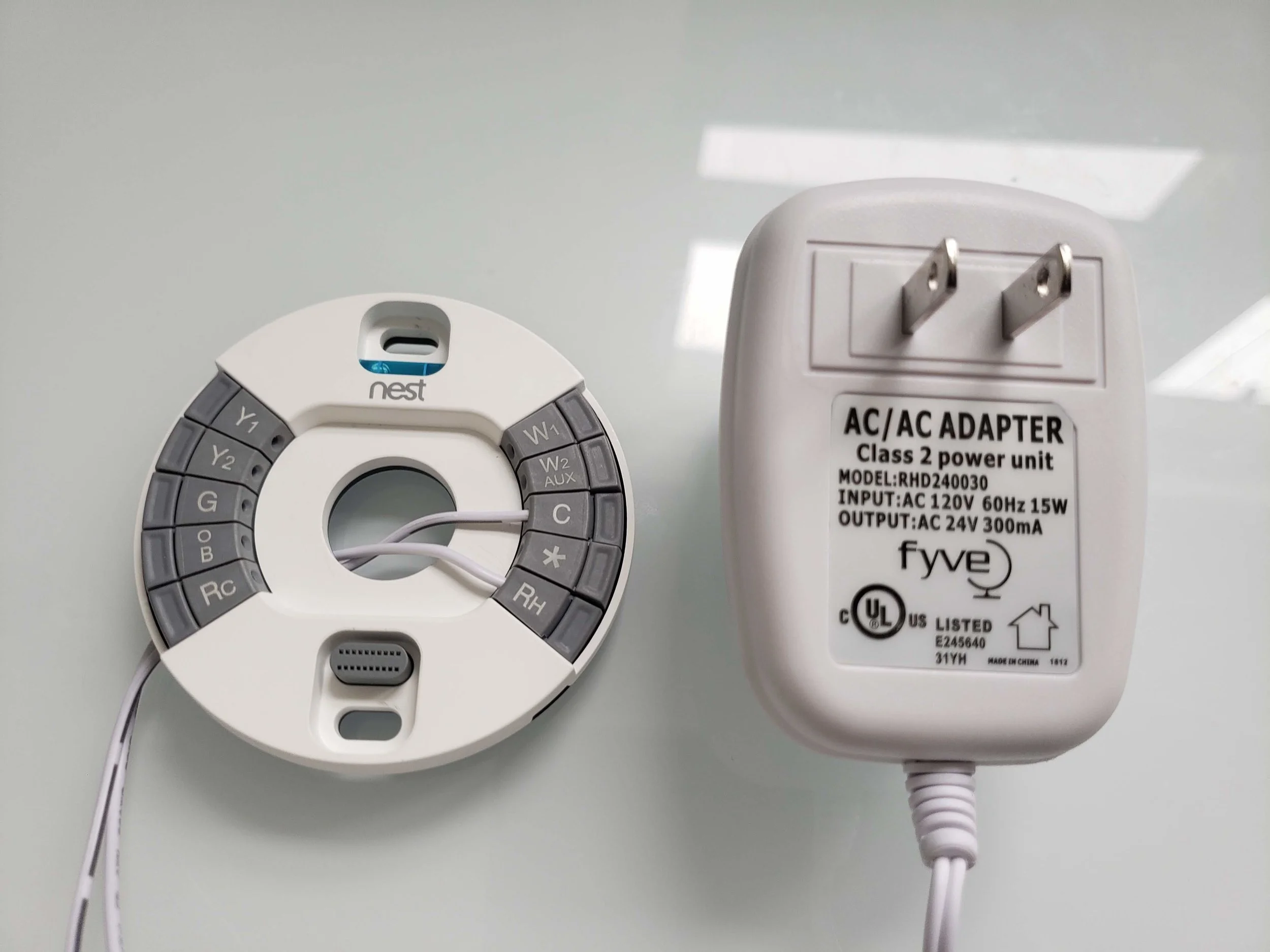
Thermostat transformer wiring describes the electrical connections that enable a thermostat to control the operation of an HVAC system (heating, ventilation, and air conditioning). The transformer itself is a device that converts the low voltage of the thermostat’s control circuit to the higher voltage required by the heating or cooling equipment.
The wiring of the thermostat transformer is crucial for ensuring proper communication between the thermostat and the HVAC system. It involves connecting the transformer’s primary terminals to the thermostat’s control circuit and the secondary terminals to the power supply and the HVAC equipment. Correct wiring ensures that the thermostat can effectively regulate the temperature of the building or space.
Understanding thermostat transformer wiring is essential for electrical contractors, HVAC technicians, and homeowners alike. It plays a vital role in maintaining comfortable indoor environments and optimizing energy consumption. One significant historical development in thermostat wiring is the switch from mercury-based thermostats to digital thermostats, which offer greater accuracy and efficiency. This transition has revolutionized temperature control and improved the performance of HVAC systems.
Thermostat transformer wiring, the electrical connections that enable a thermostat to control an HVAC system, encompasses several essential aspects that impact its functionality and effectiveness. These aspects are crucial for ensuring proper communication between the thermostat and the HVAC equipment, thereby maintaining comfortable indoor environments and optimizing energy consumption.
- Voltage conversion: The transformer converts the low voltage of the thermostat’s control circuit to the higher voltage required by the HVAC equipment.
- Circuit isolation: The transformer isolates the thermostat’s control circuit from the power supply, protecting the thermostat from electrical surges and faults.
- Wire gauge: The thickness of the wires used for the transformer’s connections affects the current-carrying capacity and voltage drop.
- Wire type: The type of wire used, such as copper or aluminum, impacts the conductivity and durability of the connections.
- Polarity: Correct polarity is essential to ensure proper functioning of the transformer and the HVAC system.
- Grounding: Proper grounding protects against electrical hazards and ensures reliable operation of the transformer.
- Connections: Secure and reliable connections are crucial for maintaining a stable electrical circuit.
- Safety codes: Compliance with electrical safety codes is essential to prevent accidents and ensure safe operation.
These aspects are interconnected and must be carefully considered during the installation and maintenance of thermostat transformer wiring. Understanding these aspects empowers electrical contractors, HVAC technicians, and homeowners to ensure the optimal performance and safety of their HVAC systems.
Voltage conversion
Within the broader scope of “Thermostat Transformer Wiring”, the aspect of “Voltage conversion” holds significant importance. It is the process by which the transformer elevates the low voltage of the thermostat’s control circuit to the higher voltage required by the HVAC equipment. This conversion is crucial for ensuring effective communication and control between the thermostat and the HVAC system.
- Transformer construction: The transformer itself consists of two coils of wire, the primary coil and the secondary coil, wound around a laminated iron core. The primary coil is connected to the thermostat’s control circuit, while the secondary coil is connected to the HVAC equipment.
- Voltage transformation: When an alternating current (AC) flows through the primary coil, it creates a magnetic field in the iron core. This magnetic field then induces an AC current in the secondary coil. The ratio of the number of turns in the primary coil to the number of turns in the secondary coil determines the voltage transformation ratio.
- Voltage requirements: Thermostats typically operate on low voltage, ranging from 24 volts AC to 120 volts AC. On the other hand, HVAC equipment, such as furnaces and air conditioners, require higher voltage, typically 120 volts AC or 240 volts AC. The transformer bridges this voltage gap, allowing the thermostat to effectively control the HVAC equipment.
- Safety and isolation: The transformer also provides electrical isolation between the thermostat’s control circuit and the HVAC equipment. This isolation is crucial for safety, as it prevents high voltage from reaching the thermostat and potentially causing damage or harm.
In summary, the voltage conversion aspect of thermostat transformer wiring is essential for enabling the thermostat to effectively control the HVAC system. It involves the use of a transformer to elevate the voltage from the thermostat’s control circuit to the higher voltage required by the HVAC equipment. This ensures proper communication, safety, and efficient operation of the HVAC system.
Circuit isolation
Within the realm of “Thermostat Transformer Wiring”, the concept of “Circuit isolation” stands as a crucial facet, ensuring the safety and reliability of the system. It refers to the transformer’s ability to electrically isolate the thermostat’s control circuit from the power supply, safeguarding the thermostat from potential damage caused by electrical surges and faults.
- Electrical surges: Electrical surges are sudden, short-term increases in voltage that can occur due to various factors, such as lightning strikes or power grid fluctuations. These surges can reach high voltage levels, posing a significant threat to electronic devices like thermostats. The transformer’s isolation prevents these surges from reaching the thermostat’s control circuit, protecting its delicate components from damage.
- Electrical faults: Electrical faults are abnormal conditions that can occur within an electrical system, such as short circuits or ground faults. These faults can cause excessive current to flow, leading to overheating, damage to components, and potential fire hazards. The transformer’s isolation helps contain the effects of such faults within the power supply, preventing them from propagating to the thermostat’s control circuit.
- Ground faults: Ground faults occur when an electrical current escapes from its intended path and flows into the ground. This can happen due to insulation breakdown or other issues. The transformer’s isolation prevents ground faults from affecting the thermostat’s control circuit, ensuring its continued safe operation.
- Safety and reliability: The overall safety and reliability of a thermostat transformer wiring system is greatly enhanced by circuit isolation. By protecting the thermostat from electrical surges and faults, the transformer ensures that the thermostat can continue to function properly, accurately controlling the HVAC system and maintaining a comfortable indoor environment.
In summary, the “Circuit isolation” aspect of thermostat transformer wiring is critical for the protection and reliable operation of the thermostat. It involves isolating the thermostat’s control circuit from the power supply, preventing damage from electrical surges, faults, and ground faults. This isolation contributes to the overall safety, reliability, and longevity of the HVAC system.
Wire gauge
In the context of “Thermostat Transformer Wiring”, the aspect of “Wire gauge” holds significant importance as it directly impacts the functionality, efficiency, and safety of the system. Wire gauge refers to the thickness of the wires used for the transformer’s connections, and it plays a crucial role in determining the current-carrying capacity and voltage drop within the circuit.
- Current-carrying capacity: The thickness of the wire determines its ability to carry electrical current without overheating. Thicker wires have a higher current-carrying capacity, allowing them to handle larger electrical loads without excessive resistance. In thermostat transformer wiring, the current-carrying capacity of the wires must be carefully considered to ensure that they can adequately support the electrical demands of the HVAC system.
- Voltage drop: As electrical current flows through a wire, there is a voltage drop due to the resistance of the wire. Thicker wires have lower resistance, resulting in less voltage drop over a given distance. In thermostat transformer wiring, excessive voltage drop can lead to reduced performance or even malfunction of the HVAC system. Therefore, the wire gauge must be selected to minimize voltage drop and maintain optimal system operation.
- Wire insulation: The thickness of the wire also affects the type of insulation required. Thicker wires can accommodate thicker insulation, which provides better protection against electrical shocks and short circuits. Proper insulation is crucial for ensuring the safety and reliability of the thermostat transformer wiring system.
- Code compliance: The selection of wire gauge must adhere to electrical codes and standards. These codes specify the minimum wire gauge that can be used for different applications, ensuring that the wiring is safe and meets industry best practices.
In summary, the “Wire gauge” aspect of thermostat transformer wiring plays a vital role in determining the current-carrying capacity, voltage drop, insulation requirements, and code compliance of the system. By carefully selecting the appropriate wire gauge, electrical contractors and HVAC technicians can ensure the efficient and safe operation of thermostat transformer wiring, ultimately contributing to the comfort and energy efficiency of the building.
Wire type
In the context of “Thermostat Transformer Wiring”, the choice of wire type is crucial as it directly affects the system’s performance, longevity, and safety. The type of wire used, whether copper or aluminum, has significant implications for the conductivity, durability, and overall reliability of the wiring system.
- Conductivity: Copper is a superior conductor of electricity compared to aluminum, meaning it offers less resistance to the flow of electrical current. This higher conductivity results in reduced voltage drop and energy loss over the length of the wire, ensuring efficient operation of the thermostat transformer wiring system.
- Durability: Copper is a more durable material than aluminum, making it more resistant to corrosion, oxidation, and mechanical damage. This enhanced durability contributes to the longevity and reliability of the wiring system, reducing the risk of wire failures and ensuring consistent performance over time.
- Flexibility: Aluminum is a more flexible material than copper, making it easier to bend and maneuver during installation. This flexibility can be advantageous in tight spaces or when complex routing is required. However, excessive bending can compromise the integrity of the wire, so care must be taken during installation.
- Cost: Aluminum is generally less expensive than copper, making it a more cost-effective option for large-scale wiring projects. However, the higher conductivity and durability of copper may justify its premium cost in applications where performance and reliability are critical.
In conclusion, the selection of wire type for thermostat transformer wiring involves carefully considering factors such as conductivity, durability, flexibility, and cost. By understanding the implications of each wire type, electrical contractors and HVAC technicians can make informed decisions that optimize the performance, safety, and longevity of the wiring system.
Polarity
Within the context of “Thermostat Transformer Wiring”, polarity plays a crucial role in ensuring the proper operation of the transformer and the HVAC system. Polarity refers to the correct orientation of the electrical connections, ensuring that current flows in the intended direction.
Incorrect polarity can lead to several issues:
- Transformer damage: Reversing the polarity of the transformer’s primary or secondary connections can cause the transformer to overheat and potentially fail.
- HVAC system malfunction: Incorrect polarity can prevent the HVAC system from operating correctly, leading to problems such as the furnace not igniting or the air conditioner not cooling.
To avoid these issues, it is essential to ensure correct polarity when wiring the thermostat transformer. This involves connecting the wires from the thermostat to the corresponding terminals on the transformer, maintaining the proper orientation.
Real-life examples of polarity issues in thermostat transformer wiring include:
- A furnace that does not ignite due to reversed polarity in the thermostat wiring.
- An air conditioner that fails to cool properly because of incorrect polarity in the transformer connections.
Understanding the importance of polarity in thermostat transformer wiring is crucial for electrical contractors and HVAC technicians. By ensuring correct polarity, they can prevent equipment damage, ensure proper system operation, and enhance the safety and reliability of the HVAC system.
In summary, polarity is a critical aspect of thermostat transformer wiring, and maintaining correct polarity is essential for the proper functioning of the transformer and the HVAC system. Incorrect polarity can lead to equipment damage and system malfunctions, highlighting the importance of careful attention to polarity during installation and maintenance.
Grounding
In the context of thermostat transformer wiring, grounding plays a vital role in ensuring the safety and reliability of the system. Grounding refers to the electrical connection between the transformer’s metal enclosure or frame and the earth ground, providing a path for electrical current to flow safely in the event of a fault.
Proper grounding achieves two primary objectives:
- Protection against electrical hazards: In the event of a fault within the transformer or the connected equipment, grounding provides a low-resistance path for electrical current to flow into the earth, preventing dangerous voltages from accumulating on the transformer’s enclosure. This reduces the risk of electrical shock, fire, and other hazards.
- Reliable operation of the transformer: Grounding helps stabilize the transformer’s electrical potential, ensuring reliable operation even under transient voltage conditions. It prevents the buildup of static charges and minimizes the risk of insulation breakdown, which can lead to transformer failure.
Real-life examples of the importance of grounding in thermostat transformer wiring include:
- A grounded transformer prevented a serious electrical accident when a fault occurred within the transformer, diverting the fault current safely into the earth.
- Proper grounding ensured the continued operation of a heating system during a power surge, preventing discomfort and potential damage.
Understanding the significance of grounding in thermostat transformer wiring is crucial for electrical contractors and HVAC technicians. By ensuring proper grounding, they can enhance the safety and reliability of the HVAC system, protecting both personnel and equipment.
In summary, grounding is an essential component of thermostat transformer wiring, serving the critical functions of protecting against electrical hazards and ensuring reliable transformer operation. Proper grounding minimizes the risk of electrical accidents, prevents equipment damage, and contributes to the overall safety and efficiency of the HVAC system.
Connections
Within the context of thermostat transformer wiring, the significance of secure and reliable connections cannot be overstated. These connections are the backbone of the system, ensuring the stable and efficient flow of electrical current throughout the circuit.
Loose or faulty connections can have detrimental effects on the system’s functionality and safety. Loose connections can increase electrical resistance, leading to voltage drop, power loss, and overheating. In severe cases, loose connections can cause arcing and sparking, posing a fire hazard. Faulty connections, on the other hand, can disrupt the flow of current entirely, leading to system malfunctions and equipment damage.
Real-life examples of the importance of secure connections in thermostat transformer wiring include:
- A loose connection in the thermostat wiring caused intermittent operation of the heating system, leading to discomfort and potential health risks.
- A faulty connection in the transformer’s secondary circuit resulted in a complete loss of power to the HVAC system, requiring immediate repair.
Understanding the critical role of secure and reliable connections in thermostat transformer wiring empowers electrical contractors and HVAC technicians to prioritize proper installation and maintenance practices. By ensuring that all connections are tight, secure, and free of corrosion or damage, they can minimize the risk of system failures, enhance safety, and optimize the performance of the HVAC system.
In summary, secure and reliable connections are a cornerstone of effective thermostat transformer wiring. Loose or faulty connections can compromise the system’s functionality, safety, and energy efficiency. By recognizing the importance of secure connections, and adhering to best practices during installation and maintenance, electrical professionals can ensure the reliable and efficient operation of thermostat transformer wiring systems.
Safety codes
In the domain of “Thermostat Transformer Wiring”, adherence to electrical safety codes stands as a paramount concern, ensuring the prevention of accidents and the safe operation of the system. These codes encompass a comprehensive set of regulations and guidelines established by governing bodies to safeguard individuals and property from electrical hazards.
- Proper Installation: Electrical safety codes mandate that thermostat transformer wiring be installed by qualified electricians who possess the knowledge and expertise to ensure compliance with established standards. This includes adhering to specified wire gauges, connection methods, and grounding requirements.
- Component Approval: Safety codes require the use of approved components, such as transformers, wires, and connectors, that meet industry standards and have undergone rigorous testing to guarantee their safety and reliability.
- Regular Inspection and Maintenance: Electrical safety codes emphasize the importance of regular inspection and maintenance of thermostat transformer wiring systems to identify and address potential hazards. This includes checking for loose connections, damaged insulation, and any signs of overheating.
- Grounding and Bonding: Proper grounding and bonding are essential safety measures required by electrical codes. Grounding provides a low-resistance path for fault currents to flow into the earth, while bonding ensures that all exposed metal surfaces are electrically connected to prevent the accumulation of dangerous voltages.
Compliance with electrical safety codes in thermostat transformer wiring is not merely a legal obligation but a crucial step towards safeguarding lives and property. By adhering to these codes, electrical contractors and HVAC technicians can minimize the risk of electrical fires, shocks, and other hazards, ensuring the safe and efficient operation of HVAC systems.


Related Posts


