A switch loop wiring diagram delineates the electrical connections between multiple light switches and lighting fixtures, enabling the control of multiple light sources from various locations. Its primary purpose is to provide flexibility and convenience in lighting management.
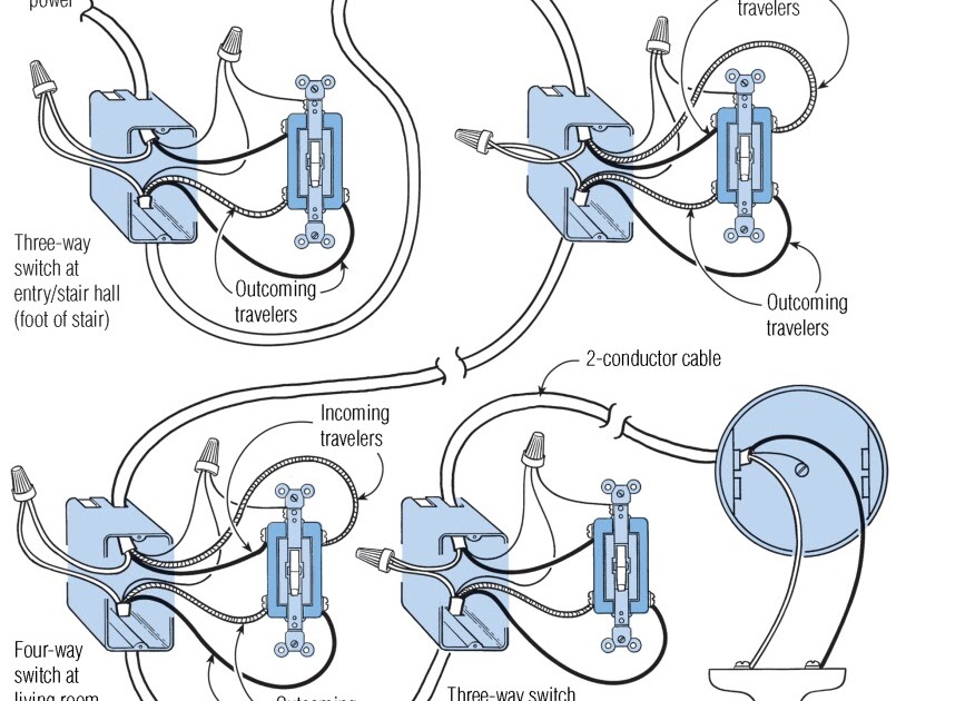
A classic example is a three-way switch setup, where two switches at different locations control a single light. The wiring diagram specifies the connections between the switches, the light fixture, and the power source, ensuring that either switch can toggle the light on or off.
The relevance of switch loop wiring diagrams lies in their versatility and efficiency in controlling lighting systems. They offer added convenience, flexibility, and energy management potential. Key historical developments include the introduction of three-way and four-way switches, which expanded the possibilities of lighting control.
A “Switch Loop Wiring Diagram” is a blueprint that serves as a guide for electricians, outlining the electrical connections between switches and lighting fixtures. Understanding its components is crucial for proper installation and maintenance.
- Electrical Components: Switches, wires, fixtures, power source.
- Circuit Design: Parallel or series connections, ensuring proper voltage and current flow.
- Switch Types: Single-pole, three-way, four-way, defining control capabilities.
- Wiring Methods: Conduit, cable, or direct burial, affecting installation complexity and safety.
- Load Calculations: Determining the maximum wattage the circuit can handle, preventing overloading.
- Voltage and Current Requirements: Matching electrical components to the specific voltage and current needs of the lighting system.
- Building Codes and Regulations: Adhering to safety standards and local electrical codes.
- Troubleshooting: Identifying and resolving common issues, ensuring the system’s functionality.
These aspects provide a comprehensive understanding of switch loop wiring diagrams, enabling efficient lighting control, safety, and adherence to electrical standards.
Electrical Components
Within the context of “Switch Loop Wiring Diagrams,” the electrical componentsswitches, wires, fixtures, and power sourceplay a central role in enabling the control and distribution of electricity for lighting systems. Understanding their functions and interconnections is crucial for effective design, installation, and maintenance.
- Switches: The primary control mechanism in a switch loop wiring diagram. They come in various types, such as single-pole, three-way, and four-way switches, each designed to control lighting from different locations. These switches interrupt or complete the electrical circuit, allowing users to turn lights on or off.
- Wires: Conductors that carry electrical current from the power source to the switches and lighting fixtures. Wires must be appropriately sized to handle the current load and meet safety standards. Common types include copper and aluminum wires, insulated with materials like PVC or rubber.
- Fixtures: The light-emitting units in a switch loop wiring diagram. They house the light source, which can be incandescent bulbs, fluorescent tubes, or LED modules. Fixtures come in various designs and styles, providing both illumination and aesthetic appeal.
- Power Source: The origin of electrical energy in a switch loop wiring diagram. It can be a standard electrical outlet, a dedicated circuit breaker, or a renewable energy source like solar panels. The power source provides the voltage and current necessary to operate the lighting system.
These electrical components work in conjunction to create a functional switch loop wiring diagram. Proper selection, installation, and maintenance of these components ensure efficient and safe operation of lighting systems in residential, commercial, and industrial settings.
Circuit Design
Within the context of “Switch Loop Wiring Diagrams,” circuit design plays a crucial role in ensuring the proper distribution of voltage and current throughout the electrical system. The choice between parallel and series connections directly impacts the functionality and safety of the lighting system.
In a parallel circuit, each lighting fixture is connected independently to the power source. This design allows each light to operate independently, unaffected by the state of other lights on the circuit. Parallel circuits are commonly used in switch loop wiring diagrams as they provide greater flexibility and control over individual lighting fixtures.
In contrast, a series circuit connects lighting fixtures in a , with the current flowing through each fixture in turn. This design results in the failure of all connected lights if a single fixture malfunctions or is turned off. While series circuits are less common in switch loop wiring diagrams, they can be useful in specific applications, such as decorative lighting.
Understanding the principles of parallel and series connections is critical for designing switch loop wiring diagrams that meet the specific requirements of a lighting system. Proper circuit design ensures the safe and efficient operation of the lighting system, preventing potential hazards such as overloading or electrical fires.
Switch Types
Within the realm of “Switch Loop Wiring Diagrams,” the types of switches employedsingle-pole, three-way, and four-wayplay a pivotal role in defining the control capabilities of the lighting system. Understanding their distinct characteristics and applications is crucial for designing effective and versatile lighting circuits.
-
Single-Pole Switches:
The most basic type of switch, single-pole switches control a single light fixture from one location. They are commonly used in residential and commercial settings for simple on/off control of lights. -
Three-Way Switches:
Three-way switches allow for the control of a single light fixture from two different locations. Typically used in hallways, stairwells, and large rooms, they provide added convenience and flexibility in lighting management. -
Four-Way Switches:
Four-way switches extend the control of a single light fixture to three or more locations. They are often employed in complex lighting systems, such as those found in auditoriums, churches, and large commercial buildings. -
Special-Purpose Switches:
In addition to the standard switch types, various specialized switches exist for specific applications. These include dimmer switches, motion sensor switches, and timer switches, each offering unique control capabilities tailored to different lighting needs.
The selection of the appropriate switch type depends on the desired level of control, the number of control locations, and the complexity of the lighting system. By understanding the capabilities and limitations of each switch type, electrical professionals can design switch loop wiring diagrams that meet the specific requirements of any lighting application.
Wiring Methods
Within the context of “Switch Loop Wiring Diagrams,” the selection of wiring methods, including conduit, cable, or direct burial, significantly influences installation complexity and safety. Understanding the distinct characteristics, advantages, and limitations of each method is crucial for designing and implementing effective and reliable lighting systems.
-
Conduit:
Conduits are protective pipes or tubes that house and route electrical wires. They provide mechanical protection, preventing damage to wires from external factors such as physical impact, moisture, and chemicals. Conduit systems are commonly used in commercial and industrial settings, where durability and safety are paramount. -
Cable:
Electrical cables are assemblies of insulated wires bundled together within an outer sheath. They offer flexibility and ease of installation, making them suitable for residential and commercial applications. However, cables may be more susceptible to damage compared to conduit systems. -
Direct Burial:
Direct burial involves burying electrical wires directly in the ground without the use of conduit or cable. This method is typically employed for outdoor lighting and power distribution. Direct burial requires careful selection of wires rated for underground use and proper burial depth to ensure protection from moisture and mechanical stress.
The choice of wiring method depends on factors such as the environment, installation location, desired level of protection, and budget constraints. Conduit systems provide the highest level of protection but are more complex and expensive to install. Cables offer a balance of flexibility and protection, while direct burial is a cost-effective option for outdoor applications. By considering these factors, electrical professionals can select the most appropriate wiring method for their specific switch loop wiring diagram.
Load Calculations
In electrical engineering, load calculations play a crucial role in ensuring the safe and efficient operation of electrical systems and circuits, including those in switch loop wiring diagrams. The maximum wattage a circuit can handle is a critical consideration to prevent overloading, which can lead to electrical fires, damage to equipment, and potential injury.
When designing a switch loop wiring diagram, it is essential to calculate the total wattage of all lighting fixtures connected to the circuit. This calculation considers the power consumption of each individual light source, whether incandescent bulbs, fluorescent tubes, or LED modules. By summing the wattage of all fixtures, electricians can determine the total load on the circuit.
The circuit’s maximum wattage capacity is determined by the wire gauge, circuit breaker rating, and other factors. Exceeding this capacity can result in overloading, causing the circuit breaker to trip or, in severe cases, electrical fires. Therefore, load calculations are critical in ensuring that the switch loop wiring diagram is designed to handle the intended electrical load safely and reliably.
Real-life examples of load calculations in switch loop wiring diagrams include determining the maximum wattage capacity for a lighting circuit in a residential home, a commercial office, or an industrial warehouse. By accurately calculating the total load, electricians can specify the appropriate wire size, circuit breaker rating, and other components to ensure a safe and functional lighting system.
Understanding load calculations is essential for electrical professionals and homeowners alike. It empowers them to design and maintain electrical systems that meet safety standards, prevent overloading, and ensure the efficient operation of lighting and other electrical devices.
Voltage and Current Requirements
For a switch loop wiring diagram to be effective, it’s crucial to consider the voltage and current requirements of the lighting system. These requirements directly impact the selection of electrical components, including switches, wires, and fixtures, ensuring compatibility and safe operation of the lighting system.
Electrical components must be rated to handle the voltage and current supplied by the power source. Mismatched voltage or current ratings can lead to component failure, electrical hazards, or poor lighting performance. For example, using a switch rated for a lower voltage than the power supply can cause the switch to overheat or fail, posing a safety risk.
Real-life examples of voltage and current requirements in switch loop wiring diagrams include:
- In residential lighting systems, switches and fixtures are typically rated for 120 volts, while outdoor lighting may require 240 volts.
- Commercial and industrial lighting systems often operate at higher voltages, such as 277 volts or 480 volts, requiring appropriate components rated for these voltages.
Understanding voltage and current requirements is essential for designing safe and efficient switch loop wiring diagrams. Proper matching of electrical components ensures compatibility, prevents component failure, and optimizes lighting performance. It empowers electrical professionals and homeowners to make informed decisions when selecting and installing lighting systems.
Building Codes and Regulations
In the context of switch loop wiring diagrams, building codes and regulations play a critical role in ensuring the safety and compliance of electrical installations. These codes and regulations establish minimum standards for the design, installation, and inspection of electrical systems, including switch loop wiring diagrams.
Adhering to building codes and regulations is essential for several reasons. Firstly, it helps prevent electrical fires and other hazards by ensuring that electrical systems are installed correctly and safely. Secondly, it ensures that lighting systems operate efficiently and effectively, providing adequate illumination without overloading circuits or exceeding wattage capacities. Thirdly, compliance with building codes and regulations is often a legal requirement for obtaining building permits and passing electrical inspections.
Real-life examples of building codes and regulations affecting switch loop wiring diagrams include:
- The National Electrical Code (NEC) in the United States provides detailed requirements for the installation of electrical systems, including switch loop wiring diagrams.
- Local building codes may impose additional requirements or amendments to the NEC, based on regional or municipal regulations.
Understanding building codes and regulations is crucial for electrical professionals and homeowners alike. By following these codes and regulations, they can ensure that switch loop wiring diagrams are designed and installed safely and in accordance with industry standards. This understanding helps prevent electrical hazards, ensures efficient lighting performance, and facilitates compliance with legal requirements.
Troubleshooting
Effective troubleshooting is a crucial component of switch loop wiring diagrams, as it enables the identification and resolution of common issues, ensuring the system’s functionality, safety, and efficiency. Troubleshooting involves analyzing symptoms, identifying potential causes, and implementing corrective actions to restore proper operation of the lighting system.
A critical aspect of troubleshooting switch loop wiring diagrams is understanding the relationship between components and their impact on the overall system. For instance, a faulty switch may prevent a light fixture from turning on, while a loose wire connection may cause flickering or intermittent operation. By systematically checking components and connections, electricians can pinpoint the source of the issue and implement appropriate solutions.
Real-life examples of troubleshooting switch loop wiring diagrams include:
- Identifying a blown fuse or tripped circuit breaker as the cause of a non-functioning lighting circuit.
- Replacing a faulty switch that has become worn or damaged, causing intermittent lighting operation.
- Tightening loose wire connections to eliminate flickering or buzzing sounds in light fixtures.
Understanding troubleshooting techniques empowers electrical professionals and homeowners to maintain and repair switch loop wiring diagrams effectively, ensuring the reliable operation of lighting systems. By promptly addressing and resolving common issues, they can prevent minor problems from escalating into more significant electrical hazards or costly repairs.


Related Posts


