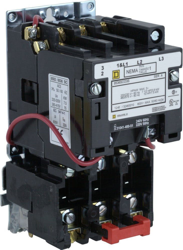
The Square D 8536 Starter Wiring Diagram outlines the electrical connections for the installation and operation of a Square D Series 8536 magnetic motor starter. It provides a detailed guide for proper wiring configuration, ensuring safe and efficient operation of the motor and starter components.
The wiring diagram is crucial for electrical professionals and technicians to ensure accurate connections between the starter, motor, power source, and control devices. It helps prevent electrical hazards, such as short circuits or improper operation, and optimizes the performance of the motor starter system.
This diagram serves as an essential tool for troubleshooting and maintaining the Square D 8536 motor starter, ensuring its longevity and preventing costly downtime. It has remained a cornerstone of industrial electrical systems since its introduction, contributing to the safe and reliable operation of motors in various applications.
Understanding the essential aspects of the “Square D 8536 Starter Wiring Diagram” is crucial for its effective utilization and safe operation of motor starter systems. As a noun, it represents a document or blueprint that provides detailed instructions for electrical connections. Exploring its key aspects allows us to delve deeper into the significance of this diagram and its various dimensions.
- Purpose: Outlines the electrical connections for installing and operating the Square D Series 8536 magnetic motor starter.
- Accuracy: Ensures proper wiring configuration, preventing electrical hazards and optimizing system performance.
- Safety: Provides a guide for safe electrical connections, reducing the risk of accidents and protecting equipment.
- Troubleshooting: Serves as a reference for identifying and resolving electrical issues, minimizing downtime and maintenance costs.
- Maintenance: Facilitates regular maintenance and inspection of the motor starter system, enhancing its longevity and reliability.
- Efficiency: Promotes efficient operation of the motor starter, optimizing energy consumption and reducing operating expenses.
- Compliance: Adherence to the wiring diagram ensures compliance with electrical codes and standards, reducing legal liabilities and ensuring safety.
- Compatibility: Specifically designed for the Square D Series 8536 motor starter, ensuring compatibility and optimal performance.
- Availability: Widely accessible through technical documentation or online resources, making it readily available for electrical professionals.
These key aspects collectively highlight the importance of the Square D 8536 Starter Wiring Diagram in ensuring the safe, efficient, and reliable operation of motor starter systems. It serves as a valuable tool for electrical professionals, contributing to the smooth functioning of industrial and commercial electrical systems.
Purpose
The primary purpose of the Square D 8536 Starter Wiring Diagram is to provide detailed instructions for the electrical connections necessary to install and operate the Square D Series 8536 magnetic motor starter. This purpose is critical to the diagram’s overall function, as it serves as a guide for electrical professionals to ensure the safe and efficient operation of the motor starter system.
Without the wiring diagram, electrical professionals would be left to determine the correct electrical connections based on their knowledge and experience, which could lead to errors or improper installation. The diagram eliminates this risk by providing a clear and comprehensive guide that ensures the motor starter is connected correctly, reducing the chances of electrical hazards or malfunctions.
A real-life example of the purpose of the Square D 8536 Starter Wiring Diagram is in the installation of a motor starter system in an industrial setting. The diagram would be used to guide the electrician in connecting the motor starter to the power source, the motor, and the control devices. By following the instructions in the diagram, the electrician can ensure that the motor starter is installed correctly, reducing the risk of accidents or damage to equipment.
Understanding the purpose of the Square D 8536 Starter Wiring Diagram is essential for electrical professionals to safely and effectively install and operate motor starter systems. The diagram provides a critical component of the overall system, ensuring the proper electrical connections for optimal performance and safety.
Accuracy
Within the context of the Square D 8536 Starter Wiring Diagram, accuracy is of paramount importance as it ensures the correct electrical connections necessary for the safe and efficient operation of the motor starter system.
- Precise Wiring Configuration: The diagram provides detailed instructions for connecting the motor starter to the power source, motor, and control devices, ensuring that each component is properly connected to its designated terminals. This precision reduces the risk of incorrect connections, which could lead to electrical hazards or malfunctions.
- Hazard Prevention: By ensuring proper wiring configuration, the diagram helps prevent electrical hazards such as short circuits, overloads, and ground faults. These hazards can cause damage to equipment, electrical fires, or even personal injury. The accuracy of the diagram minimizes these risks by providing a clear and concise guide for safe electrical connections.
- Optimized System Performance: The diagram also contributes to optimizing the performance of the motor starter system. Correct wiring ensures that the motor starter functions efficiently, reducing energy consumption and maximizing the lifespan of the connected equipment. Accurate wiring also minimizes downtime caused by electrical issues, improving productivity and reducing maintenance costs.
- Compliance with Standards: Adhering to the wiring diagram promotes compliance with electrical codes and safety standards. This compliance ensures that the motor starter system meets the required safety and performance criteria, reducing legal liabilities and protecting personnel and property.
In summary, the accuracy of the Square D 8536 Starter Wiring Diagram plays a crucial role in ensuring the proper wiring configuration, preventing electrical hazards, optimizing system performance, and promoting compliance with safety standards. This accuracy is essential for the safe and efficient operation of motor starter systems in various industrial and commercial applications.
Safety
The “Safety: Provides a guide for safe electrical connections, reducing the risk of accidents and protecting equipment” aspect is a critical component of the “Square D 8536 Starter Wiring Diagram” as it ensures the proper configuration and installation of the motor starter system, minimizing electrical hazards and protecting personnel and equipment. The wiring diagram provides detailed instructions on how to safely connect the motor starter to the power source, motor, and control devices, reducing the risk of incorrect connections that could lead to accidents or damage.
A real-life example of the safety aspect within the “Square D 8536 Starter Wiring Diagram” is the inclusion of instructions on how to properly ground the motor starter system. Grounding is essential for protecting against electrical shock and preventing damage to equipment in the event of a fault. The wiring diagram ensures that the motor starter is properly grounded, reducing the risk of electrical accidents and protecting personnel.
The practical applications of understanding the safety aspect of the “Square D 8536 Starter Wiring Diagram” extend to various industrial and commercial settings where motor starter systems are used. By following the instructions in the diagram, electrical professionals can ensure the safe installation, operation, and maintenance of motor starter systems, reducing the risk of accidents, protecting equipment, and ensuring compliance with safety regulations.
Troubleshooting
Within the context of the “Square D 8536 Starter Wiring Diagram,” the troubleshooting aspect plays a crucial role in maintaining the safe and efficient operation of the motor starter system. The wiring diagram serves as a reference guide for electrical professionals to identify and resolve electrical issues, minimizing downtime and maintenance costs.
- Fault Tracing and Diagnosis: The wiring diagram provides a systematic approach to troubleshooting electrical faults within the motor starter system. It enables technicians to trace the electrical connections and identify potential points of failure, such as loose connections, damaged components, or incorrect wiring.
- Real-Life Example: Consider a scenario where the motor starter fails to operate. By referring to the wiring diagram, a technician can systematically check the power supply, control circuit, and motor connections to pinpoint the source of the fault.
- Reduced Downtime: Prompt troubleshooting minimizes downtime by enabling technicians to quickly identify and resolve electrical issues. This reduces the time and resources spent on maintenance, allowing the motor starter system to resume operation efficiently.
- Cost Optimization: Accurate troubleshooting helps avoid unnecessary part replacements and repairs by guiding technicians to the root cause of the problem. This optimizes maintenance costs and extends the lifespan of the motor starter system.
In summary, the troubleshooting aspect of the “Square D 8536 Starter Wiring Diagram” is essential for maintaining the reliability and cost-effectiveness of the motor starter system. By providing a structured approach to fault identification and resolution, the wiring diagram empowers electrical professionals to minimize downtime, optimize maintenance costs, and ensure the safe and efficient operation of the system.
Maintenance
Within the context of the “Square D 8536 Starter Wiring Diagram,” the maintenance aspect is crucial for ensuring the long-term performance and reliability of the motor starter system. The wiring diagram provides detailed guidance on how to perform regular maintenance and inspection tasks, enabling electrical professionals to proactively identify potential issues and prevent costly breakdowns.
- Inspection and Cleaning: The wiring diagram includes instructions on how to inspect the motor starter system for loose connections, corrosion, or damage. Regular cleaning helps remove dust and debris that can impair the performance and lifespan of the components.
- Contact Maintenance: The wiring diagram provides guidance on maintaining the electrical contacts within the motor starter. This includes cleaning and adjusting the contacts to ensure proper electrical connections and minimize resistance.
- Lubrication: The wiring diagram specifies the lubrication requirements for the motor starter system. Proper lubrication reduces friction and wear, extending the lifespan of the components and ensuring smooth operation.
- Thermal Monitoring: The wiring diagram includes instructions on how to monitor the temperature of the motor starter system. Overheating can indicate potential issues, and early detection enables timely intervention to prevent damage.
By following the maintenance guidelines outlined in the “Square D 8536 Starter Wiring Diagram,” electrical professionals can effectively maintain the motor starter system, minimizing the risk of unexpected failures, extending its lifespan, and ensuring reliable operation.
Efficiency
Within the context of the “Square D 8536 Starter Wiring Diagram,” the emphasis on efficiency is paramount, as it directly affects the performance and cost-effectiveness of the motor starter system. The wiring diagram provides detailed instructions on how to configure and operate the system to maximize efficiency, minimizing energy consumption and reducing operating expenses.
- Optimal Motor Selection: The wiring diagram guides the selection of a motor that is appropriately sized for the specific application. Oversized motors consume more energy than necessary, while undersized motors can lead to premature failure. Proper motor selection ensures efficient operation and reduces energy costs.
- Efficient Starting Methods: The wiring diagram outlines various starting methods, such as reduced voltage starting or soft starting. These methods reduce the inrush current and torque during motor startup, resulting in lower energy consumption and reduced stress on the motor and other components.
- Energy-Saving Features: The wiring diagram includes instructions on how to incorporate energy-saving features, such as variable frequency drives (VFDs) or energy-efficient lighting, into the motor starter system. These features can significantly reduce energy consumption and operating costs.
- Maintenance and Monitoring: The wiring diagram provides guidelines for regular maintenance and monitoring of the motor starter system. Proper maintenance, such as cleaning and lubrication, ensures optimal performance and efficiency. Monitoring the system allows for early detection of potential issues, preventing costly breakdowns and extending the lifespan of the components.
By following the efficiency-oriented recommendations outlined in the “Square D 8536 Starter Wiring Diagram,” electrical professionals can configure, operate, and maintain motor starter systems that are highly efficient, minimizing energy consumption and reducing operating expenses. This contributes to the overall sustainability and cost-effectiveness of industrial and commercial operations.
Compliance
Within the context of “Square D 8536 Starter Wiring Diagram,” the aspect of compliance plays a vital role in ensuring the safe and lawful operation of the motor starter system. Adhering to the wiring diagram promotes compliance with established electrical codes and industry standards, mitigating legal risks and safeguarding personnel, equipment, and the facility itself.
- Conformance to Electrical Codes: The wiring diagram aligns with recognized electrical codes, such as the National Electrical Code (NEC) or local building codes. By following the diagram’s instructions, electrical professionals can be confident that the motor starter system meets the minimum safety requirements, reducing the risk of electrical hazards and accidents.
- Adherence to Industry Standards: The wiring diagram incorporates best practices and standards established by industry organizations, such as the National Electrical Manufacturers Association (NEMA) or the Institute of Electrical and Electronics Engineers (IEEE). This adherence ensures that the motor starter system is designed, installed, and operated according to recognized industry guidelines, enhancing safety and reliability.
- Reduced Legal Liability: Compliance with electrical codes and standards helps reduce the legal liability of the installer, owner, or operator of the motor starter system. By adhering to the wiring diagram, they can demonstrate due diligence and adherence to established safety regulations, mitigating potential legal consequences in the event of an accident or mishap.
- Improved Insurance Coverage: Insurance companies often require compliance with electrical codes and standards as a condition for coverage. Adhering to the wiring diagram can improve the insurability of the motor starter system, ensuring adequate protection against financial losses in the event of an electrical incident.
In summary, compliance with electrical codes and standards through adherence to the “Square D 8536 Starter Wiring Diagram” is essential for ensuring the safe and lawful operation of the motor starter system. It reduces legal liabilities, improves insurance coverage, and enhances the overall safety and reliability of the system, benefiting all stakeholders involved.
Compatibility
Within the context of the “Square D 8536 Starter Wiring Diagram,” the aspect of compatibility plays a crucial role in ensuring the seamless operation and efficiency of the motor starter system. The wiring diagram is specifically designed to be compatible with the Square D Series 8536 motor starter, guaranteeing optimal performance and safe operation.
The compatibility between the wiring diagram and the motor starter is a critical component, as it ensures that the electrical connections are configured correctly. The diagram provides precise instructions on how to connect the power source, motor, and control devices to the motor starter, ensuring that each component is properly integrated into the system. This compatibility minimizes the risk of incorrect connections, which could lead to electrical hazards, equipment damage, or system malfunctions.
A real-life example of the importance of compatibility can be seen in industrial settings where motor starter systems are used to control electric motors. In such environments, the Square D 8536 Starter Wiring Diagram is essential for ensuring that the motor starter is properly connected to the motor and other components. By following the instructions in the diagram, electricians can ensure that the motor starter is compatible with the specific motor being used, optimizing the system’s performance and preventing potential issues.
The practical applications of understanding the compatibility aspect of the “Square D 8536 Starter Wiring Diagram” extend to various industries and applications where motor starter systems are employed. Electrical professionals rely on the diagram to ensure the compatibility between the motor starter and other system components, maximizing efficiency, reliability, and safety. This understanding is crucial for maintaining optimal performance, minimizing downtime, and ensuring the longevity of the motor starter system.
Availability
In the realm of electrical engineering, reliable access to accurate information is paramount. The “Square D 8536 Starter Wiring Diagram” exemplifies this principle through its widespread availability, ensuring that electrical professionals have the resources they need to install, maintain, and troubleshoot motor starter systems efficiently and effectively.
- Online Accessibility: The wiring diagram is readily available online, allowing electrical professionals to access it from any location with an internet connection. This eliminates the need for physical manuals and facilitates quick reference during on-site work.
- Technical Documentation: The wiring diagram is also included in technical documentation provided by Square D, ensuring that it is easily accessible to professionals who prefer printed materials. This dual availability provides flexibility and convenience.
- Comprehensive Coverage: The wiring diagram is available in various formats, including PDFs, CAD drawings, and interactive online tools. This comprehensive coverage ensures that electrical professionals can access the diagram in the format that best suits their needs.
- Global Reach: The availability of the wiring diagram extends beyond geographical boundaries. It is accessible to electrical professionals worldwide, fostering knowledge sharing and ensuring that best practices are followed regardless of location.
The widespread availability of the “Square D 8536 Starter Wiring Diagram” empowers electrical professionals with the necessary information to confidently perform their tasks. It contributes to the safety, efficiency, and reliability of motor starter systems, ultimately benefiting industries and organizations that rely on electrical equipment.


Related Posts


