A Senville Mini Split Wiring Diagram is a detailed visual representation of the electrical connections required to install a Senville brand mini split air conditioning and heating unit. It provides a step-by-step guide, outlining the proper wiring for all electrical components, including the outdoor unit, indoor unit, and power source. For example, a Senville Mini Split Wiring Diagram for a 12,000 BTU unit might include a schematic of the refrigerant lines, electrical connections, and wiring between the indoor and outdoor units.
These diagrams are essential for ensuring the safe and efficient operation of a mini split system. They help to avoid electrical hazards, incorrect wiring, and potential damage to the equipment. Additionally, they facilitate troubleshooting, making it easier to diagnose and repair any issues that may arise with the system.
Historically, the use of wiring diagrams has been crucial in the development and advancements of electrical systems. They have enabled engineers and technicians to design and construct complex electrical circuits with precision and reliability. Today, wiring diagrams remain a fundamental tool in the field of electrical engineering and are essential for the safe and efficient installation and maintenance of electrical systems, including mini split air conditioners and heaters.
Understanding the essential aspects of a Senville Mini Split Wiring Diagram is crucial for ensuring the safe and efficient installation, operation, and maintenance of a mini split air conditioning and heating system. These diagrams provide comprehensive visual representations of the electrical connections required for these systems, making them an invaluable tool for technicians, contractors, and homeowners alike.
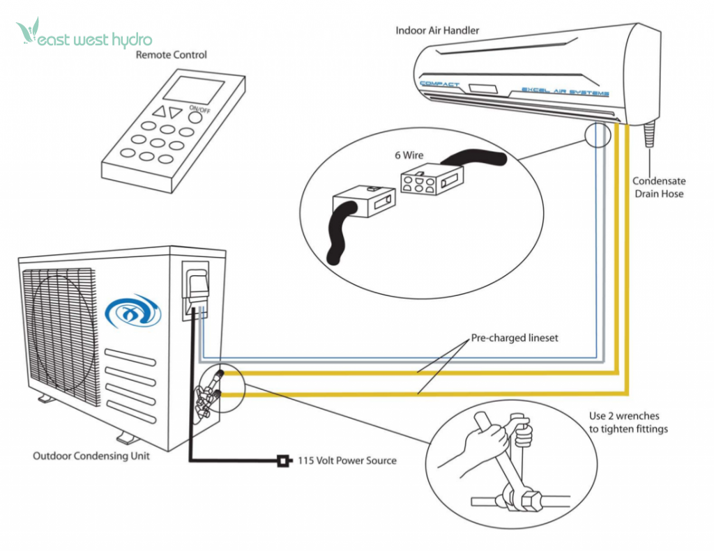
- Components: Outdoor unit, indoor unit, power source, wires, connectors
- Connections: Electrical wiring between components, including power, signal, and refrigerant lines
- Codes: Compliance with electrical codes and standards, ensuring safety and reliability
- Troubleshooting: Identifying and resolving electrical issues, minimizing downtime
- Installation: Step-by-step guidance for proper installation, preventing errors
- Maintenance: Instructions for routine maintenance, extending system lifespan
- Safety: Precautions and warnings for handling electrical components, avoiding hazards
- Efficiency: Optimizing electrical connections for maximum system efficiency
These aspects are interconnected and essential for the proper functioning of a Senville Mini Split Wiring Diagram. By understanding these aspects, technicians and homeowners can ensure that their mini split systems operate safely, efficiently, and reliably for many years to come. For example, proper attention to electrical codes and standards during installation can prevent electrical fires and other hazards, while regular maintenance can identify potential issues before they lead to costly repairs or system failure.
Components
The components of a Senville Mini Split Wiring Diagram outdoor unit, indoor unit, power source, wires, and connectors play a critical role in the safe and efficient operation of the system. The outdoor unit houses the compressor and condenser, while the indoor unit contains the evaporator and blower. The power source provides the electrical power to operate the system, and the wires and connectors establish the electrical connections between the components.
A Senville Mini Split Wiring Diagram is essential for ensuring that all of these components are properly connected and operating in harmony. Without a proper wiring diagram, it would be difficult to ensure that the system is operating safely and efficiently. For example, incorrect wiring could lead to electrical fires, damage to the equipment, or even personal injury.
Real-life examples of the components of a Senville Mini Split Wiring Diagram include:
- Outdoor unit: Typically located on the exterior of the building, the outdoor unit houses the compressor and condenser.
- Indoor unit: Mounted on the interior wall of the building, the indoor unit contains the evaporator and blower.
- Power source: The power source provides the electrical power to operate the system. This can be a dedicated circuit or a branch circuit from the main electrical panel.
- Wires: The wires connect the outdoor and indoor units to the power source.
- Connectors: The connectors establish the electrical connections between the wires and the components.
Understanding the relationship between the components of a Senville Mini Split Wiring Diagram is essential for the safe and efficient installation and operation of the system. By following the wiring diagram carefully, technicians can ensure that all of the components are properly connected and operating in harmony. This will help to prevent electrical hazards, damage to the equipment, and personal injury.
Connections
The connections between the electrical wiring components, including power, signal, and refrigerant lines, are crucial to the operation of a Senville Mini Split Wiring Diagram. These connections allow the different components of the system to communicate and function together properly. Without these connections, the system would not be able to operate.
The power connections provide the electrical power to operate the compressor, fan, and other components of the system. The signal connections allow the different components of the system to communicate with each other. The refrigerant lines allow the refrigerant to flow between the indoor and outdoor units.
Real-life examples of the connections between the electrical wiring components, including power, signal, and refrigerant lines, within a Senville Mini Split Wiring Diagram include:
- The power connection between the outdoor unit and the indoor unit
- The signal connection between the thermostat and the indoor unit
- The refrigerant lines between the indoor unit and the outdoor unit
Understanding the connections between the electrical wiring components, including power, signal, and refrigerant lines, is essential for the proper installation and operation of a Senville Mini Split Wiring Diagram. By following the wiring diagram carefully, technicians can ensure that all of the components are properly connected and operating in harmony. This will help to prevent electrical hazards, damage to the equipment, and personal injury.
Codes
Electrical codes and standards are established to ensure the safe and reliable operation of electrical systems, including Senville Mini Split Wiring Diagrams. These codes and standards provide guidelines for the installation, maintenance, and repair of electrical equipment and wiring. By following these codes and standards, technicians can help to prevent electrical fires, shocks, and other hazards.
For example, the National Electrical Code (NEC) is a set of electrical safety standards that are used in the United States. The NEC requires that all electrical wiring be installed in accordance with its provisions. These provisions include requirements for the type of wire that can be used, the size of the wire, and the way that the wire is installed. By following the NEC, technicians can help to ensure that electrical systems are safe and reliable.
Real-life examples of the importance of compliance with electrical codes and standards within Senville Mini Split Wiring Diagrams include:
- Using the correct wire size for the amperage of the circuit
- Installing wires in a way that prevents them from being damaged
- Using the proper connectors for the type of wire being used
- Grounding all electrical components properly
Understanding the connection between codes, compliance with electrical codes and standards, ensuring safety and reliability, and Senville Mini Split Wiring Diagrams is essential for the safe and efficient installation and operation of these systems. By following the electrical codes and standards, technicians can help to prevent electrical hazards, damage to the equipment, and personal injury.
Troubleshooting
Troubleshooting electrical issues in a Senville Mini Split Wiring Diagram is vital for maintaining system efficiency and preventing costly repairs. Armed with the ability to identify and resolve electrical issues, technicians can minimize system downtime, ensuring optimal performance and occupant comfort.
-
Electrical Component Inspection
A thorough inspection of electrical components, including wires, connectors, and terminals, can reveal loose connections, corrosion, or damage that may disrupt system operation. Using a multimeter to check for continuity and proper voltage levels helps pinpoint faulty components.
-
Refrigerant Charge Verification
Inadequate or excessive refrigerant charge can lead to electrical issues. Measuring refrigerant pressure and comparing it to manufacturer specifications ensures optimal system performance. Adjusting the charge as needed can resolve electrical faults caused by refrigerant-related problems.
-
Circuit Breaker and Fuse Inspection
Overloaded circuits or faulty circuit breakers and fuses can cause electrical interruptions. Inspecting these components for proper operation and replacing them if necessary restores power and prevents further electrical damage.
-
Wiring Diagram Analysis
Referring to the Senville Mini Split Wiring Diagram enables technicians to trace electrical connections, identify potential issues, and verify the correct wiring configuration. This step-by-step analysis helps troubleshoot complex electrical faults and ensures accurate repairs.
Effectively troubleshooting electrical issues in a Senville Mini Split Wiring Diagram requires a systematic approach, attention to detail, and a thorough understanding of electrical principles. By following these steps and leveraging the insights gained from each facet, technicians can efficiently resolve electrical problems, minimize downtime, and restore system performance, ensuring a reliable and comfortable indoor environment.
Installation
The installation of a Senville Mini Split Wiring Diagram requires meticulous attention to detail, and the step-by-step guidance provided in the diagram is essential for ensuring a proper and error-free installation. The diagram outlines the precise sequence of steps involved in connecting the electrical components, including the outdoor unit, indoor unit, power source, and refrigerant lines. By following these instructions carefully, technicians can avoid common mistakes such as incorrect wire sizing, improper connections, and refrigerant leaks, which could lead to system malfunctions, safety hazards, and reduced efficiency.
One real-life example of the importance of following the installation guidance in a Senville Mini Split Wiring Diagram is the proper connection of the refrigerant lines. If these lines are not connected properly, the refrigerant may leak, which can damage the system and pose a safety hazard. The wiring diagram provides detailed instructions on how to connect the refrigerant lines, including the correct type of fittings and the amount of torque to apply when tightening the connections. By following these instructions, technicians can ensure that the refrigerant lines are connected securely and that there are no leaks.
Understanding the connection between installation guidance and Senville Mini Split Wiring Diagrams is critical for ensuring that the system is installed correctly and operates safely and efficiently. By following the step-by-step instructions provided in the diagram, technicians can avoid costly mistakes and ensure that the system is installed to the manufacturer’s specifications. This will help to extend the life of the system, reduce energy consumption, and provide years of trouble-free operation.
In conclusion, the installation guidance provided in a Senville Mini Split Wiring Diagram is an essential component of the safe and efficient installation of the system. By following these instructions carefully, technicians can avoid errors, ensure proper operation, and extend the life of the system.
Maintenance
Maintenance plays a pivotal role in the longevity and performance of any system, and a Senville Mini Split Wiring Diagram is no exception. By following the maintenance instructions provided in the diagram, homeowners and technicians can ensure the system operates at optimal efficiency, identify potential issues early on, and extend its lifespan.
-
Filter Cleaning or Replacement
Regular cleaning or replacement of air filters is crucial to maintain proper airflow, prevent dust buildup, and ensure efficient heat exchange. Clogged filters can impede airflow, reduce cooling or heating capacity, and strain the system, leading to premature wear and tear.
-
Coil Cleaning
Cleaning the coils on both the indoor and outdoor units is essential to remove dirt, debris, and mold that can accumulate over time. Dirty coils reduce heat transfer efficiency, leading to higher energy consumption and reduced system performance.
-
Refrigerant Level Inspection
Periodically checking the refrigerant level is important to ensure optimal system operation. Low refrigerant levels can affect cooling or heating capacity and put additional stress on the compressor, potentially leading to costly repairs or premature failure.
-
Electrical Connections Inspection
Inspecting electrical connections for any signs of corrosion, loose wires, or damage is crucial to prevent electrical hazards and ensure the system operates safely and reliably. Loose connections can lead to arcing, overheating, and even electrical fires.
By incorporating these maintenance tasks into a regular routine, homeowners and technicians can proactively safeguard their Senville Mini Split system, ensuring years of trouble-free operation, energy efficiency, and a comfortable indoor environment. Neglecting maintenance can lead to decreased system performance, higher energy bills, and costly repairs in the long run.
Safety
When dealing with electrical components, particularly in the context of a Senville Mini Split Wiring Diagram, safety should be the utmost priority. The diagram serves as a guide for installing and maintaining the electrical connections of a mini split system, and adhering to the safety precautions and warnings outlined within it is crucial to prevent electrical hazards, accidents, and potential harm to individuals and property.
One of the primary reasons why safety precautions are a critical component of a Senville Mini Split Wiring Diagram is that working with electricity poses inherent risks. Incorrect handling or mishandling of electrical components can lead to electrical shocks, fires, or even electrocution. By providing clear instructions and warnings, the diagram helps ensure that individuals performing the electrical work have the necessary knowledge and understanding to carry out the tasks safely.
Real-life examples of safety precautions and warnings found in a Senville Mini Split Wiring Diagram include:
- Instructions on how to properly ground the system to prevent electrical shocks
- Warnings against overloading circuits, which can lead to overheating and fires
- Cautions to avoid touching live wires or terminals, which can cause electrical shocks
- Guidance on proper wire sizing and insulation to prevent overheating and electrical fires
Understanding the connection between safety precautions and warnings and the Senville Mini Split Wiring Diagram is essential for ensuring that electrical work is carried out safely and in compliance with industry standards and regulations. By following the guidelines and adhering to the safety measures outlined in the diagram, individuals can minimize the risks associated with electrical work and contribute to the safe and efficient operation of the mini split system.
Efficiency
In the context of a Senville Mini Split Wiring Diagram, the concept of efficiency, particularly optimizing electrical connections for maximum system efficiency, plays a crucial role in ensuring the optimal performance and energy-saving capabilities of the mini split system.
A Senville Mini Split Wiring Diagram provides a comprehensive guide for installing and connecting the electrical components of a mini split system, including the outdoor unit, indoor unit, power source, and refrigerant lines. By carefully following the instructions and guidelines outlined in the diagram, technicians and homeowners can ensure that the electrical connections are optimized for maximum system efficiency.
Real-life examples of how efficiency is maximized through optimized electrical connections within a Senville Mini Split Wiring Diagram include:
- Proper wire sizing: The wiring diagram specifies the appropriate wire size for each electrical connection, ensuring that the wires can handle the electrical current without overheating or causing energy loss.
- Correct wire routing: The diagram provides guidance on how to route the wires to minimize electrical resistance and avoid interference with other electrical components.
- Tight electrical connections: Loose electrical connections can lead to arcing and energy loss. The wiring diagram emphasizes the importance of making tight and secure electrical connections.
Understanding the connection between efficiency and optimized electrical connections in a Senville Mini Split Wiring Diagram is critical for achieving optimal system performance. By adhering to the guidelines and recommendations provided in the diagram, technicians and homeowners can ensure that the mini split system operates at peak efficiency, resulting in energy savings, reduced operating costs, and a more comfortable indoor environment.
![[25+] Daikin Mini Split Wiring Diagram, Pioneer Mini Split Wiring](https://i0.wp.com/i.ytimg.com/vi/rv7LxO754PQ/maxresdefault.jpg?w=665&ssl=1)


Related Posts


