Definition: An Rc Car Wiring Diagram is a schematic representation of the electrical connections within a radio-controlled (RC) car. It provides a visual guide that shows how the various components, such as the battery, motor, receiver, and servos, are wired together.
Core Function: Its core function is to ensure that the electrical system of the RC car is connected correctly and operates effectively. By following the diagram, users can troubleshoot electrical issues, identify loose connections, and make necessary repairs or modifications.
Transition: Understanding and interpreting Rc Car Wiring Diagrams is crucial for enthusiasts and hobbyists who want to build, maintain, and customize their RC cars. This article delves into the intricacies of these diagrams, exploring their components, best practices, and the evolution of wiring techniques in the RC hobby.
In the realm of RC car enthusiasts, the importance of understanding the essential aspects of Rc Car Wiring Diagrams cannot be overstated. These diagrams serve as blueprints for the electrical systems of RC cars, providing a roadmap for assembly, maintenance, and troubleshooting.
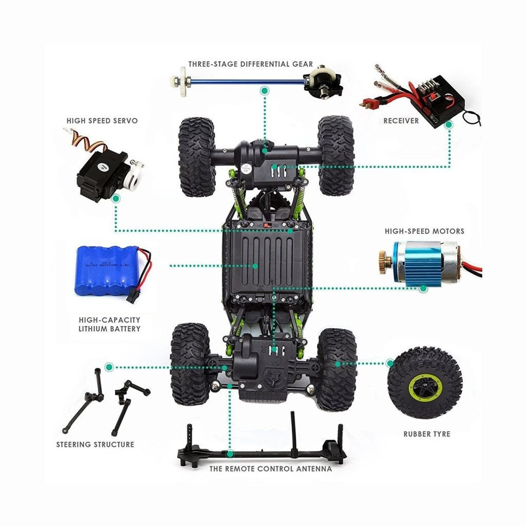
- Components: Understanding the different components of an RC car wiring diagram, such as batteries, motors, receivers, and servos, is crucial for proper wiring.
- Circuit Design: The circuit design dictates the flow of electricity through the car’s electrical system, affecting performance and efficiency.
- Wire Gauge: Choosing the correct wire gauge ensures that wires can handle the electrical current without overheating or causing damage.
- Soldering Techniques: Proper soldering techniques create reliable electrical connections, preventing loose wires and malfunctions.
- Connector Types: Understanding the various types of connectors used in RC car wiring diagrams helps in selecting the right ones for specific applications.
- Testing and Troubleshooting: Knowing how to test and troubleshoot wiring diagrams enables users to identify and resolve electrical issues.
- Safety Precautions: Adhering to safety precautions while working with electrical systems minimizes the risk of accidents and damage.
- Digital Diagrams: Digital wiring diagrams offer advantages such as easy editing, sharing, and accessibility.
- Customization: Wiring diagrams allow enthusiasts to customize their RC cars’ electrical systems for enhanced performance or specific requirements.
- Compatibility: Ensuring compatibility between different components and the wiring diagram is essential for proper functioning.
These key aspects provide a comprehensive understanding of Rc Car Wiring Diagrams, empowering hobbyists to build, maintain, and modify their RC cars with confidence and precision.
Components
In the realm of RC car wiring diagrams, understanding the individual components and their roles is paramount for successful electrical system assembly and maintenance.
- Batteries: Batteries provide the electrical power for the RC car. They come in various types, such as NiMH, LiPo, and LiFe, each with its own characteristics and voltage output. Choosing the right battery for the specific RC car and application is essential for optimal performance and safety.
- Motors: Motors convert electrical energy into mechanical energy, powering the wheels of the RC car. Different types of motors, such as brushed and brushless, offer varying levels of efficiency, torque, and speed. Selecting the appropriate motor for the desired performance and terrain is crucial.
- Receivers: Receivers capture and decode radio signals from the transmitter, relaying commands to the servos and other components. They act as the central communication hub of the RC car’s electrical system. Compatibility between the transmitter and receiver is essential for reliable control.
- Servos: Servos convert electrical signals into precise mechanical movements, controlling steering, throttle, and other functions of the RC car. Different types of servos, such as analog and digital, provide varying levels of precision and response time. Selecting the right servos for the specific application ensures optimal control and handling.
Understanding the roles and characteristics of these components empowers RC enthusiasts to make informed decisions when designing, building, and maintaining their RC car’s electrical system, ensuring optimal performance, reliability, and longevity.
Circuit Design
Circuit design is a critical component of Rc Car Wiring Diagrams as it determines the flow of electricity throughout the system. An efficient and well-designed circuit allows for optimal performance, longer battery life, and reduced risk of component damage. Conversely, a poorly designed circuit can lead to inefficiencies, power loss, and potential safety hazards.
Real-life examples of circuit design considerations within Rc Car Wiring Diagrams include:
- Power Distribution: The circuit design should ensure proper power distribution to all components, considering the current draw and voltage requirements of each.
- Voltage Regulation: Voltage regulators may be incorporated into the circuit to maintain stable voltage levels, protecting sensitive components from fluctuations.
- EMI Shielding: Circuits can be designed with shielding to minimize electromagnetic interference, preventing erratic behavior or signal loss.
- Fuse Protection: Fuses can be included in the circuit to protect components from damage caused by electrical overloads or short circuits.
- Cooling Considerations: High-power circuits may require additional cooling measures, such as heat sinks or fans, to prevent overheating.
Understanding circuit design principles empowers RC enthusiasts to create efficient and reliable electrical systems for their RC cars. By optimizing circuit design, they can enhance performance, extend component life, and ensure the safe operation of their RC vehicles.
Wire Gauge
In the context of Rc Car Wiring Diagrams, wire gauge plays a critical role in ensuring the safe and efficient operation of the electrical system. Wires with an appropriate gauge can handle the electrical current required by the components without overheating or causing damage, preventing potential hazards and performance issues.
Real-life examples of the importance of wire gauge in Rc Car Wiring Diagrams include:
- Battery to Motor: The wire gauge used for the connection between the battery and motor should be able to handle the high current draw of the motor during operation, preventing voltage drop and power loss.
- Receiver to Servos: The wires connecting the receiver to the servos should have an appropriate gauge to ensure reliable signal transmission and control, minimizing latency and ensuring precise movements.
- Power Distribution: When multiple components are connected to a single power source, the wire gauge should be sized to handle the combined current draw, preventing overloading and potential damage to the components.
Understanding the relationship between wire gauge and electrical current is essential for RC enthusiasts to design and build safe and reliable Rc Car Wiring Diagrams. By choosing the correct wire gauge for each connection, they can optimize performance, extend component life, and minimize the risk of electrical hazards.
Soldering Techniques
In the context of Rc Car Wiring Diagrams, proper soldering techniques are critical for ensuring reliable electrical connections throughout the system. Soldered joints create a strong and permanent bond between wires and components, preventing loose connections that can lead to intermittent operation, power loss, or even damage to components.
Real-life examples of the importance of soldering techniques within Rc Car Wiring Diagrams include:
- Battery Connections: Soldering the battery wires to the motor and ESC ensures a solid connection for high current flow, minimizing voltage drop and maintaining consistent power delivery.
- Receiver and Servo Connections: Properly soldered connections between the receiver and servos guarantee reliable signal transmission and precise control, preventing erratic movements or loss of control.
- Circuit Board Connections: Soldering components onto circuit boards creates secure electrical connections, preventing shorts, open circuits, and component failure.
Understanding the importance of proper soldering techniques empowers RC enthusiasts to create robust and reliable Rc Car Wiring Diagrams. By mastering these techniques, they can ensure that their RC cars perform optimally, with minimal risk of electrical issues or component damage.
Connector Types
In the realm of Rc Car Wiring Diagrams, connector types play a pivotal role in ensuring reliable electrical connections throughout the system. Selecting the appropriate connectors for specific applications is crucial to maintain signal integrity, prevent power loss, and avoid potential damage to components.
- Power Connectors: Power connectors handle the high current flow between batteries, motors, and ESCs. Common types include T-connectors, XT60 connectors, and EC5 connectors, each offering varying levels of current capacity and ease of use.
- Signal Connectors: Signal connectors transmit control signals between the receiver and servos, ensuring precise and responsive control. JST connectors and Futaba connectors are widely used, providing reliable signal transmission in various RC applications.
- Battery Connectors: Battery connectors provide a secure connection between batteries and the ESC, ensuring efficient power delivery. Common types include Deans connectors, EC3 connectors, and Traxxas connectors, designed to handle different battery configurations and current ratings.
- Specialized Connectors: Specialized connectors are used for specific components and accessories, such as LED lights, cameras, or GPS modules. These connectors often feature unique designs and pin configurations to ensure compatibility with specific devices.
Understanding connector types empowers RC enthusiasts to select the right connectors for their specific wiring needs, ensuring optimal performance, reliability, and longevity of their RC cars.
Testing and Troubleshooting
Within the context of Rc Car Wiring Diagrams, testing and troubleshooting skills are indispensable for maintaining optimal performance and resolving electrical issues. By understanding testing and troubleshooting techniques, RC enthusiasts can diagnose and fix problems, ensuring the smooth operation of their RC cars. This involves understanding circuit behavior, identifying potential faults, and implementing appropriate solutions.
- Electrical Continuity Testing: Using a multimeter to check for electrical continuity ensures that current flows through the circuit as intended. This helps identify broken wires, loose connections, or faulty components.
- Voltage Measurement: Measuring voltage at various points in the circuit helps identify voltage drops, incorrect connections, or battery issues. This information aids in diagnosing power supply problems.
- Signal Tracing: Using an oscilloscope or logic analyzer to trace signals through the circuit helps verify signal integrity and identify issues with signal transmission, interference, or component malfunctions.
- Component Testing: Testing individual components, such as motors, servos, or ESCs, helps isolate faulty components and determine if they need repair or replacement.
By mastering testing and troubleshooting techniques, RC enthusiasts gain the ability to diagnose and resolve electrical issues efficiently. This empowers them to maintain their RC cars in optimal condition, minimize downtime, and enhance the overall driving experience.
Safety Precautions
Within the context of Rc Car Wiring Diagrams, adhering to safety precautions is paramount to ensure the well-being of individuals and prevent damage to equipment. Electrical systems, especially those involving batteries and high-power components, pose potential hazards if handled improperly.
One critical aspect of safety precautions involves understanding the electrical characteristics of components and circuits. Rc Car Wiring Diagrams provide a roadmap for connecting these components, but it is essential to have a fundamental grasp of voltage, current, and resistance to avoid short circuits, overloads, or electrocution.
Real-life examples of safety precautions within Rc Car Wiring Diagrams include proper insulation of wires, using appropriate fuse ratings, and ensuring secure connections to prevent arcing or overheating. Additionally, precautions such as wearing appropriate protective gear, working in a well-ventilated area, and keeping flammable materials away from electrical components are crucial.
By understanding the importance of safety precautions and applying them diligently, RC enthusiasts can minimize the risks associated with working with electrical systems. This not only protects their personal safety but also ensures the longevity and reliability of their Rc Car Wiring Diagrams and the RC cars they power.
Digital Diagrams
Digital wiring diagrams have revolutionized the landscape of Rc Car Wiring Diagrams, bringing forth a multitude of advantages. Their digital nature empowers RC enthusiasts with unprecedented ease of editing, sharing, and accessibility, enhancing the overall experience of designing, building, and maintaining RC cars.
- Portability and Accessibility: Digital diagrams can be easily stored and accessed on various devices, such as laptops, tablets, and smartphones. This portability allows RC enthusiasts to work on their wiring diagrams anytime, anywhere, without the need for physical copies.
- Collaborative Editing: Digital diagrams enable seamless collaboration among multiple users. They can be shared online, allowing team members to simultaneously view, edit, and comment on the diagram, facilitating efficient and effective teamwork.
- Version Control: Digital diagrams offer robust version control features, allowing users to track changes, revert to previous versions, and maintain a history of modifications. This ensures that the latest and most accurate version of the wiring diagram is always available.
- Simulation and Analysis: Some digital diagramming tools offer simulation and analysis capabilities. These tools can simulate the behavior of the electrical circuit, allowing users to identify potential issues, optimize circuit design, and make informed decisions.
The advent of digital diagrams has transformed the way RC enthusiasts approach wiring diagrams. Their ease of editing, sharing, and accessibility have made it easier than ever to create, modify, and troubleshoot Rc Car Wiring Diagrams, empowering RC enthusiasts to build and maintain their RC cars with greater efficiency, accuracy, and confidence.
Customization
Within the realm of Rc Car Wiring Diagrams, customization stands as a key aspect, empowering enthusiasts to tailor their RC cars’ electrical systems to meet specific performance goals or unique requirements. This level of customization goes beyond the basic functionality of the wiring diagram, enabling RC enthusiasts to unlock the full potential of their RC cars.
- Performance Enhancements: Wiring diagrams provide a platform for enthusiasts to optimize the performance of their RC cars by modifying circuit designs, selecting higher-performance components, and implementing custom configurations. These modifications can result in increased speed, improved handling, and enhanced power output.
- Unique Features: Customization allows RC enthusiasts to add unique features to their RC cars, such as custom lighting systems, sound modules, or specialized sensors. By incorporating these features into the wiring diagram, enthusiasts can personalize their RC cars and make them stand out from the crowd.
- Specific Requirements: Wiring diagrams empower enthusiasts to adapt their RC cars to specific requirements or applications. For instance, they can modify the wiring to accommodate different types of motors, batteries, or radio systems, enabling them to tailor their RC cars for specific terrains, racing classes, or personal preferences.
- Experimental Modifications: The flexibility of wiring diagrams encourages experimentation and innovation. Enthusiasts can test different circuit configurations, try out new components, and explore the limits of their RC cars’ capabilities. This experimentation can lead to groundbreaking designs and novel applications.
Overall, the customization aspect of Rc Car Wiring Diagrams grants RC enthusiasts unparalleled control over the electrical systems of their RC cars. By understanding and leveraging the principles of wiring diagrams, they can unleash their creativity, optimize performance, and create RC cars that are truly one-of-a-kind.
Compatibility
Within the realm of Rc Car Wiring Diagrams, compatibility plays a pivotal role in ensuring the seamless operation and performance of RC cars. Compatibility refers to the ability of different components, such as batteries, motors, servos, and receivers, to work together harmoniously within the electrical system.
- Component Compatibility: Ensuring compatibility between different components is crucial. Incompatible components can lead to malfunctions, reduced performance, or even damage to the system. For instance, using a motor that draws excessive current for the ESC’s rating can result in overheating and burnout.
- Voltage and Current Matching: The voltage and current requirements of each component must be compatible with the wiring diagram and power source. Mismatched voltage or current can cause damage to components or poor system performance. For example, connecting a high-voltage battery to a receiver designed for a lower voltage can lead to receiver failure.
- Signal Compatibility: In RC cars, signals are transmitted between components to control movement and functions. Incompatible signal protocols or frequencies can disrupt communication and result in erratic behavior or loss of control. Ensuring compatibility between transmitters, receivers, and servos is essential.
- Connector Compatibility: Physical connectors must be compatible to ensure proper electrical connections. Using incompatible connectors can lead to loose connections, intermittent operation, or damage to components. Choosing the right connectors for the specific components and wiring diagram is crucial.
Compatibility in Rc Car Wiring Diagrams is paramount for reliable and efficient operation. By understanding the compatibility requirements of different components and carefully selecting compatible parts, RC enthusiasts can ensure that their RC cars perform optimally, minimizing the risk of malfunctions and damage.


Related Posts


