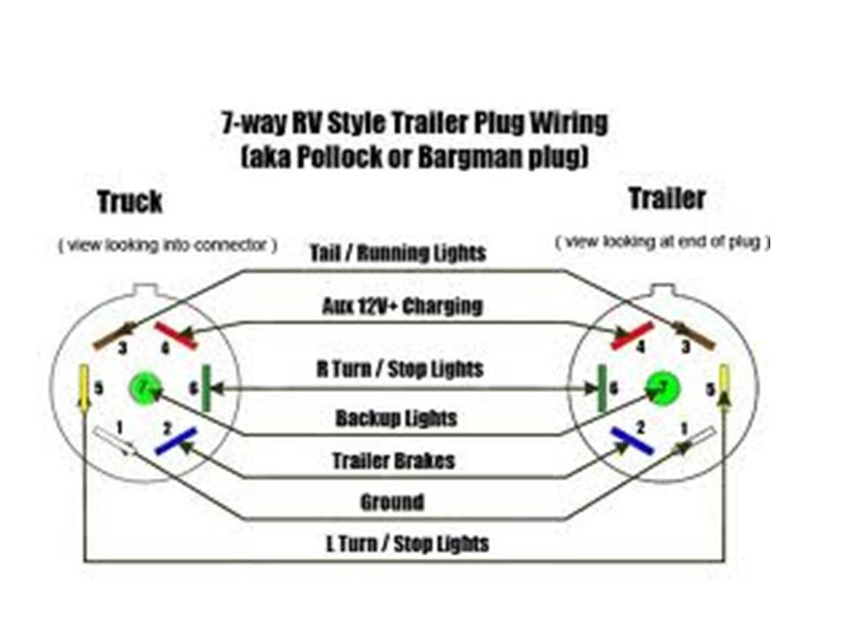
Definition and example: A Pollak Trailer Plug Wiring Diagram is an illustration that denotes the proper wiring connections between a tow vehicle and a trailer. It specifies the color-coded wires and their corresponding functions, ensuring a secure and functional electrical connection between the two. As an example, the diagram might depict the wiring for running lights, brake lights, turn signals, and auxiliary power.
Importance, benefits, and historical context: This diagram is crucial for establishing a reliable electrical connection between a tow vehicle and a trailer. Ensuring proper wiring prevents malfunctions or safety hazards, such as inoperable lights or brake systems. The standardization of trailer wiring diagrams, like those provided by Pollak, has significantly contributed to the ease and safety of trailer hookups.
Transition to main article topics: Understanding the Pollak Trailer Plug Wiring Diagram is essential for any individual involved in towing and trailer operations. The following article will delve into the specifics of the diagram, including the color coding, wire gauge requirements, and proper installation techniques. By providing clear and concise information, this article aims to enhance the safety and efficiency of trailer wiring practices.
Understanding the essential aspects of the Pollak Trailer Plug Wiring Diagram is crucial for ensuring the safety and functionality of trailer connections. These aspects encompass various dimensions related to the diagram, including its components, connections, and implications.
- Color Coding: The diagram specifies the color-coded wires and their corresponding functions, ensuring consistent and standardized wiring practices.
- Wire Gauge: It denotes the appropriate wire gauge for each function, ensuring proper current-carrying capacity and preventing overheating.
- Connection Types: The diagram illustrates the types of connectors used, such as butt connectors, ring terminals, and heat shrink, providing guidance on secure and reliable electrical connections.
- Grounding: The diagram emphasizes the importance of proper grounding, ensuring a complete electrical circuit and preventing electrical faults.
- Testing: It includes guidelines for testing the electrical connections using a multimeter or test light, verifying the functionality of the wiring system.
- Troubleshooting: The diagram serves as a reference for troubleshooting electrical issues, identifying potential causes and providing solutions.
- Legal Compliance: Adhering to the diagram’s specifications ensures compliance with safety regulations and industry standards.
- Compatibility: The diagram considers the compatibility of different trailer plug types, ensuring proper connections between tow vehicles and trailers of various makes and models.
These aspects collectively contribute to the safe and efficient operation of trailers by establishing reliable electrical connections between tow vehicles and trailers. By understanding and following the Pollak Trailer Plug Wiring Diagram, individuals can ensure proper lighting, braking, and auxiliary power functions, minimizing the risk of electrical malfunctions or accidents.
Color Coding: The diagram specifies the color-coded wires and their corresponding functions, ensuring consistent and standardized wiring practices.
Within the context of the Pollak Trailer Plug Wiring Diagram, color coding plays a pivotal role in establishing a uniform and error-free wiring system for trailer connections. It assigns specific colors to different wire functions, facilitating quick identification, proper connections, and efficient troubleshooting.
- Standardized Functions: The color coding adheres to industry standards, ensuring that each color represents a specific function across different makes and models of tow vehicles and trailers. This standardization simplifies wiring practices and reduces the risk of misconnections.
- Easy Identification: The distinct colors of the wires allow for easy identification during installation, maintenance, or repairs. This visual cue helps technicians quickly trace wires, locate faults, and make necessary adjustments, saving time and effort.
- Reduced Wiring Errors: Color coding minimizes the likelihood of wiring errors by providing a clear visual guide. By matching the colored wires to their designated terminals, installers can avoid incorrect connections that could lead to electrical malfunctions or safety hazards.
- Simplified Troubleshooting: In the event of electrical issues, the color coding assists in troubleshooting by enabling technicians to isolate the affected circuit quickly. By tracing the colored wires, they can pinpoint the source of the problem and implement appropriate solutions.
In summary, the color coding aspect of the Pollak Trailer Plug Wiring Diagram serves as a fundamental element in promoting consistent and standardized wiring practices for trailer connections. It enhances safety, simplifies installation and maintenance, and facilitates efficient troubleshooting, ultimately contributing to the reliable operation of trailers.
Wire Gauge: It denotes the appropriate wire gauge for each function, ensuring proper current-carrying capacity and preventing overheating.
Within the context of the Pollak Trailer Plug Wiring Diagram, wire gauge holds paramount importance in ensuring the safe and efficient operation of trailer connections. It specifies the appropriate thickness or diameter of the wires used for each function, directly impacting their current-carrying capacity and ability to prevent overheating.
- Current-Carrying Capacity: The wire gauge determines the maximum amount of electrical current that can safely flow through the wire without overheating. Using wires with insufficient gauge for the intended current load can lead to overheating, insulation damage, and potential fire hazards.
- Voltage Drop: Wire gauge also influences voltage drop, which is the reduction in voltage that occurs as electricity flows through the wire. Thicker gauge wires have less resistance, resulting in lower voltage drop and ensuring that electrical devices receive the necessary voltage to operate properly.
- Wire Size and Flexibility: The wire gauge dictates the physical size and flexibility of the wire. Thicker gauge wires are larger in diameter and less flexible, while thinner gauge wires are smaller and more flexible. This aspect must be considered during installation, as the flexibility of the wire affects its ease of routing and connection.
- Industry Standards: The Pollak Trailer Plug Wiring Diagram adheres to industry standards that specify the recommended wire gauge for different trailer functions. These standards consider factors such as the power requirements of lighting, braking, and auxiliary systems, ensuring compatibility and safety across various makes and models of tow vehicles and trailers.
In summary, the specification of appropriate wire gauge in the Pollak Trailer Plug Wiring Diagram is a crucial aspect that ensures the safe and reliable operation of trailer connections. By adhering to the recommended wire gauge for each function, installers can prevent overheating, maintain proper voltage levels, and ensure the optimal performance of all electrical components within the trailer system.
Connection Types: The diagram illustrates the types of connectors used, such as butt connectors, ring terminals, and heat shrink, providing guidance on secure and reliable electrical connections.
Within the context of the Pollak Trailer Plug Wiring Diagram, the specification of appropriate connection types is crucial for establishing secure and reliable electrical connections between tow vehicles and trailers. The diagram illustrates the types of connectors used, ensuring proper mating, low resistance, and protection against environmental factors.
- Butt Connectors: These are commonly used to join two wires of the same gauge. They are twisted around the exposed wire ends and crimped using a crimping tool, creating a secure and permanent connection.
- Ring Terminals: These are crimped onto the end of a wire and have a circular loop at the other end. Ring terminals are designed to connect wires to bolts or other terminals, providing a secure and reliable connection.
- Heat Shrink: Heat shrink tubing is a type of insulation that is applied over wire connections. When heated, the tubing shrinks and conforms to the shape of the connection, providing additional protection against moisture, corrosion, and strain.
- Additional Considerations: The diagram may also specify the use of solder and electrical tape to further enhance the security and reliability of the connections. Proper crimping techniques and the use of high-quality connectors are essential for ensuring long-lasting and trouble-free electrical connections.
By adhering to the specified connection types and following proper installation techniques, individuals can establish secure and reliable electrical connections for their trailer wiring, minimizing the risk of electrical faults, malfunctions, or accidents. These connection methods play a critical role in ensuring the safety and functionality of trailer electrical systems.
Grounding: The diagram emphasizes the importance of proper grounding, ensuring a complete electrical circuit and preventing electrical faults.
Within the context of the Pollak Trailer Plug Wiring Diagram, grounding plays a critical role in establishing a complete and safe electrical circuit for the trailer. Proper grounding provides a low-resistance path for electrical current to return to its source, ensuring the proper functioning of electrical components and preventing electrical faults.
- Dedicated Grounding Wire: The diagram specifies the use of a dedicated grounding wire, typically identified by its green color, to establish a direct connection between the trailer’s frame and the tow vehicle’s chassis. This dedicated grounding wire ensures a reliable path for electrical current to flow back to the source.
- Grounding Points: The diagram indicates designated grounding points on the trailer’s frame where the grounding wire should be connected. These grounding points are carefully selected to provide the best possible electrical contact with the frame, ensuring a low-resistance path for grounding.
- Electrical Safety: Proper grounding is essential for electrical safety. Without a proper ground, electrical current can take unintended paths, potentially leading to electrical shocks or fires. The grounding wire provides a safe and controlled path for electrical current to flow, minimizing the risk of electrical hazards.
- Compliance with Standards: Adhering to the grounding specifications in the Pollak Trailer Plug Wiring Diagram ensures compliance with industry standards and regulations. These standards are established to promote safety and ensure the proper functioning of trailer electrical systems.
In conclusion, the aspect of grounding in the Pollak Trailer Plug Wiring Diagram is crucial for establishing a complete and safe electrical circuit for the trailer. Proper grounding practices, including the use of a dedicated grounding wire, designated grounding points, and compliance with industry standards, are essential for ensuring the reliability and safety of trailer electrical systems.
Testing: It includes guidelines for testing the electrical connections using a multimeter or test light, verifying the functionality of the wiring system.
Within the context of the Pollak Trailer Plug Wiring Diagram, testing plays a critical role in ensuring the proper functionality and safety of the trailer’s electrical system. The diagram provides guidelines for testing the electrical connections using a multimeter or test light, enabling individuals to verify the continuity, polarity, and proper operation of the wiring system.
Testing is a crucial component of the Pollak Trailer Plug Wiring Diagram because it allows users to identify and troubleshoot any potential issues before connecting the trailer to a tow vehicle. By following the testing guidelines, individuals can ensure that the electrical connections are secure, the wiring is intact, and the system is functioning as intended. This proactive approach helps prevent electrical malfunctions, safety hazards, and costly repairs down the road.
Real-life examples of testing within the Pollak Trailer Plug Wiring Diagram include:
- Using a multimeter to check for continuity between the trailer plug and the corresponding terminals on the tow vehicle, ensuring that the electrical circuit is complete.
- Employing a test light to verify that the running lights, brake lights, and turn signals are functioning properly, indicating that the wiring connections are correct and the bulbs are intact.
- Testing the grounding connection to ensure that there is a proper path for electrical current to return to the source, minimizing the risk of electrical shocks or fires.
The practical significance of understanding the testing aspect of the Pollak Trailer Plug Wiring Diagram lies in its contribution to the safe and reliable operation of trailers. By performing these tests, individuals can proactively identify and resolve any electrical issues, ensuring that the trailer’s lighting, braking, and other electrical systems are functioning optimally. This understanding empowers individuals to maintain their trailers in good working condition, reducing the likelihood of accidents, breakdowns, and costly repairs.
In summary, the testing guidelines provided in the Pollak Trailer Plug Wiring Diagram are essential for verifying the functionality and safety of the trailer’s electrical system. By following these guidelines and performing the necessary tests, individuals can ensure that their trailers are properly wired, securely connected, and operating as intended, contributing to a safer and more enjoyable towing experience.
Troubleshooting: The diagram serves as a reference for troubleshooting electrical issues, identifying potential causes and providing solutions.
Within the context of the Pollak Trailer Plug Wiring Diagram, troubleshooting plays a crucial role in maintaining the functionality and safety of trailer electrical systems. The diagram provides a valuable resource for identifying and resolving electrical issues, ensuring that trailers operate as intended and comply with safety regulations.
The troubleshooting aspect of the Pollak Trailer Plug Wiring Diagram is a critical component as it enables users to diagnose and rectify electrical problems efficiently. By following the diagram’s guidelines and utilizing appropriate troubleshooting techniques, individuals can pinpoint the root cause of electrical malfunctions, ranging from loose connections to faulty components.
Real-life examples of troubleshooting within the Pollak Trailer Plug Wiring Diagram include:
- Identifying a blown fuse or tripped circuit breaker by checking the fuse panel or resetting the circuit breaker, restoring power to the affected electrical circuits.
- Tracing wire connections to locate damaged or disconnected wires, ensuring proper continuity and functionality of the electrical system.
- Testing electrical components, such as lights or switches, using a multimeter or test light to determine their condition and identify any necessary replacements.
The practical significance of understanding the troubleshooting aspect of the Pollak Trailer Plug Wiring Diagram lies in its contribution to the safe and reliable operation of trailers. By empowering individuals to troubleshoot and resolve electrical issues, the diagram promotes proactive maintenance and reduces the risk of accidents, breakdowns, and costly repairs. This understanding is particularly valuable for individuals who tow trailers regularly or for extended periods, as it enables them to address electrical problems promptly and effectively.
In summary, the troubleshooting guidelines provided in the Pollak Trailer Plug Wiring Diagram are essential for maintaining the functionality and safety of trailer electrical systems. By utilizing the diagram as a reference and following appropriate troubleshooting techniques, individuals can diagnose and resolve electrical issues efficiently, ensuring that their trailers operate reliably and meet safety standards.
Legal Compliance: Adhering to the diagram’s specifications ensures compliance with safety regulations and industry standards.
Within the context of the Pollak Trailer Plug Wiring Diagram, legal compliance holds paramount importance as it establishes a direct connection between the proper wiring of trailers and adherence to established safety regulations and industry standards. By following the specifications outlined in the diagram, individuals can ensure that their trailer’s electrical system meets the required safety criteria, promoting safe and compliant operation on public roadways.
The legal compliance aspect of the Pollak Trailer Plug Wiring Diagram is a critical component as it ensures that trailers are equipped with properly functioning electrical systems, including lighting, braking, and auxiliary functions. This compliance helps prevent electrical hazards, reduces the risk of accidents, and safeguards both the occupants of the towing vehicle and other road users.
Real-life examples of legal compliance within the Pollak Trailer Plug Wiring Diagram include:
- Adhering to the specified wire gauge requirements ensures that the electrical system can handle the necessary current load without overheating or causing a fire hazard.
- Proper grounding practices, as outlined in the diagram, prevent electrical shocks and potential electrocution risks.
- Correctly wired lighting systems, including running lights, brake lights, and turn signals, enhance visibility and ensure safe communication with other vehicles.
The practical significance of understanding the legal compliance aspect of the Pollak Trailer Plug Wiring Diagram lies in its contribution to public safety and the prevention of electrical-related accidents on roadways. By adhering to the diagram’s specifications, individuals demonstrate responsible ownership and contribute to a safer driving environment for all.
In summary, the legal compliance aspect of the Pollak Trailer Plug Wiring Diagram is a vital component that promotes adherence to safety regulations and industry standards. By ensuring proper trailer wiring, individuals can fulfill their legal obligations, protect themselves and others on the road, and contribute to a safer and more compliant transportation system.
Compatibility: The diagram considers the compatibility of different trailer plug types, ensuring proper connections between tow vehicles and trailers of various makes and models.
Within the context of the Pollak Trailer Plug Wiring Diagram, compatibility plays a pivotal role in establishing seamless connections between tow vehicles and trailers of varying makes and models. The diagram provides guidelines for matching the appropriate trailer plug types, ensuring a secure and functional electrical interface between the two.
Compatibility is a critical component of the Pollak Trailer Plug Wiring Diagram as it addresses the diverse electrical configurations found in different vehicles and trailers. By adhering to the specified compatibility guidelines, individuals can avoid mismatched connections, electrical faults, and potential safety hazards.
Real-life examples of compatibility within the Pollak Trailer Plug Wiring Diagram include:
- Matching the 7-pin round plug on a tow vehicle to a compatible 7-pin round receptacle on a trailer, ensuring proper connection of all electrical functions, including lighting, braking, and auxiliary power.
- Adapting a 4-pin flat plug on an older tow vehicle to a 7-pin round receptacle on a newer trailer using an appropriate adapter, allowing for the connection of essential lighting and braking functions.
- Utilizing a 5-pin flat plug on a smaller trailer to connect to a 7-pin round receptacle on a tow vehicle, ensuring a secure connection for basic lighting and braking functions.
The practical significance of understanding the compatibility aspect of the Pollak Trailer Plug Wiring Diagram lies in its contribution to the safe and reliable operation of trailers. By ensuring proper compatibility between tow vehicles and trailers, individuals can prevent electrical malfunctions, reduce the risk of accidents, and facilitate seamless towing experiences.
In summary, the compatibility aspect of the Pollak Trailer Plug Wiring Diagram is a fundamental element that promotes the safe and efficient connection of trailers to tow vehicles. Understanding and adhering to the compatibility guidelines outlined in the diagram empowers individuals to establish reliable electrical interfaces, regardless of the makes and models of the equipment involved.


![[DIAGRAM] 7 Blade Trailer Plug Wiring Diagram Pollak](https://i0.wp.com/chematron.org/image/pollak-12-705-blade-wiring-diagram-5.jpg?w=665&ssl=1)
Related Posts


