Polaris CDI Wiring DiagramA Polaris CDI wiring diagram is a technical illustration that shows the electrical connections between the various components of a Polaris all-terrain vehicle’s (ATV) or snowmobile’s capacitive discharge ignition (CDI) system. The CDI system is responsible for generating the electrical spark that ignites the fuel-air mixture in the engine’s cylinders. The wiring diagram provides a detailed guide to the electrical connections between the CDI unit, the ignition coil, the spark plugs, and other electrical components. By following the wiring diagram, a technician can troubleshoot and repair any electrical problems that may arise in the CDI system.
Importance, Benefits, and Historical ContextPolaris CDI wiring diagrams are essential for diagnosing and repairing electrical problems in Polaris ATVs and snowmobiles. Without a wiring diagram, it can be difficult to trace the electrical connections and identify the source of the problem. Wiring diagrams also provide valuable information about the electrical system’s design and operation. This information can be helpful for troubleshooting intermittent problems and making modifications to the electrical system.One key historical development in the Polaris CDI wiring diagrams was the introduction of computer-aided design (CAD) software. CAD software allows engineers to create detailed and accurate wiring diagrams that are easy to read and understand. The use of CAD software has greatly improved the quality and accuracy of Polaris CDI wiring diagrams, making them an invaluable tool for technicians.
Transition to Main Article TopicsThis article will provide a detailed overview of Polaris CDI wiring diagrams, including their importance, benefits, and historical development. The article will also provide step-by-step instructions on how to use a Polaris CDI wiring diagram to troubleshoot and repair electrical problems in Polaris ATVs and snowmobiles.
Understanding the essential aspects of Polaris CDI wiring diagrams is crucial for troubleshooting and repairing electrical problems in Polaris ATVs and snowmobiles. These diagrams provide a detailed guide to the electrical connections between the CDI unit, the ignition coil, the spark plugs, and other electrical components.
- Components: CDI unit, ignition coil, spark plugs, electrical connections
- Function: Generate electrical spark to ignite fuel-air mixture
- Troubleshooting: Diagnose and repair electrical problems
- Repair: Replace faulty components, repair damaged wires
- Design: Electrical system layout and operation
- Modifications: Customize electrical system for specific needs
- Safety: Ensure proper electrical connections to prevent accidents
- Documentation: Reference guide for technicians and owners
Each of these aspects plays a vital role in the proper functioning of the CDI system. By understanding these aspects, technicians can effectively troubleshoot and repair electrical problems, ensuring that Polaris ATVs and snowmobiles operate safely and reliably.
Components
Within the context of “Polaris CDI Wiring Diagram”, the components – CDI unit, ignition coil, spark plugs, and electrical connections – play critical roles in ensuring proper functioning of the ignition system. Understanding their significance and interconnections is essential for effective troubleshooting and repair.
- CDI Unit: The heart of the ignition system, responsible for generating and controlling the electrical pulses that trigger spark plugs.
- Ignition Coil: Acts as a transformer, amplifying the voltage from the CDI unit to create a high-voltage spark.
- Spark Plugs: Conduct the high-voltage current from the ignition coil to create a spark that ignites the fuel-air mixture.
- Electrical Connections: Wires and connectors that establish electrical pathways between the CDI unit, ignition coil, spark plugs, and other system components.
Each of these components must function properly for the engine to operate smoothly. Faulty CDI units, weak ignition coils, worn spark plugs, or loose electrical connections can lead to ignition problems, engine misfires, or even complete engine failure. Therefore, a thorough understanding of these components and their interconnections is crucial for accurate diagnosis and repair of Polaris CDI ignition systems.
Function
In the context of a Polaris CDI wiring diagram, understanding the function of generating an electrical spark to ignite the fuel-air mixture is crucial. It lies at the core of the ignition system’s operation, enabling the engine to start and run smoothly.
- CDI Unit: The CDI unit serves as the brain of the ignition system, generating and controlling the electrical pulses that trigger spark plugs.
- Ignition Coil: Acting as a transformer, the ignition coil amplifies the voltage from the CDI unit to create a high-voltage spark.
- Spark Plugs: These components conduct the high-voltage current from the ignition coil, creating a spark that ignites the fuel-air mixture in the engine’s cylinders.
- Electrical Connections: Wires and connectors establish electrical pathways between the CDI unit, ignition coil, spark plugs, and other system components, ensuring proper communication and functionality.
The precise coordination of these components ensures that the electrical spark is generated at the optimal timing, igniting the fuel-air mixture efficiently. This process is critical for maintaining engine performance, fuel economy, and emission control. A thorough understanding of how these components work together to generate an electrical spark is essential for troubleshooting and repairing Polaris CDI ignition systems.
Troubleshooting
In the context of “Polaris CDI Wiring Diagram,” “Troubleshooting: Diagnose and repair electrical problems” plays a crucial role in maintaining the optimal performance of Polaris ATVs and snowmobiles. It involves identifying and rectifying electrical faults within the CDI ignition system, ensuring reliable engine operation. This section delves into specific facets of troubleshooting, providing a detailed overview of various components, examples, and implications.
-
Identifying Faulty Components
Troubleshooting often begins with identifying faulty components within the CDI system. This may involve testing the CDI unit, ignition coil, spark plugs, and electrical connections using specialized diagnostic tools or visual inspection for signs of damage or wear.
-
Interpreting Wiring Diagrams
Polaris CDI wiring diagrams serve as essential guides for troubleshooting electrical problems. Technicians rely on these diagrams to trace electrical connections, locate specific components, and identify potential problem areas within the system.
-
Analyzing Symptoms
Troubleshooting also involves analyzing specific symptoms exhibited by the ATV or snowmobile. These symptoms may include engine misfires, difficulty starting, or intermittent electrical issues. By carefully observing and interpreting these symptoms, technicians can narrow down the potential causes of the problem.
-
Repairing Electrical Faults
Once the source of the electrical problem has been identified, appropriate repairs can be made. This may involve replacing faulty components, repairing damaged wires or connections, or reconfiguring the electrical system as per the wiring diagram.
By understanding and applying these troubleshooting techniques, technicians can effectively diagnose and repair electrical problems in Polaris CDI systems. This ensures that Polaris ATVs and snowmobiles operate safely and reliably, providing optimal performance for recreational or utility purposes.
Repair
Within the context of “Polaris Cdi Wiring Diagram,” the aspect of “Repair: Replace faulty components, repair damaged wires” plays a pivotal role in maintaining optimal performance and ensuring reliable operation of Polaris ATVs and snowmobiles. This section delves into the specific components and implications involved in repairing electrical faults, providing a comprehensive overview for technicians and enthusiasts alike.
-
Identifying Faulty Components
Diagnosing electrical problems often involves identifying faulty components within the CDI system. This may include testing the CDI unit, ignition coil, spark plugs, and electrical connections using specialized diagnostic tools or visual inspection for signs of damage or wear.
-
Replacing Faulty Components
Once faulty components have been identified, they must be replaced with new or refurbished ones. This may involve removing the old component, installing the new one, and verifying proper connections.
-
Repairing Damaged Wires
Damaged wires can cause electrical faults and disrupt the proper functioning of the CDI system. Repairing damaged wires involves identifying the damaged section, cutting it out, and splicing in a new piece of wire. Proper insulation and sealing of the repaired wire is crucial to ensure reliability and prevent future problems.
-
Testing and Verification
After replacing faulty components or repairing damaged wires, it is important to conduct thorough testing to verify that the repairs have been successful. This may involve starting the engine and observing its operation, using diagnostic tools to check for proper electrical signals, or performing a road test to assess performance under real-world conditions.
By understanding and applying these repair techniques, technicians and enthusiasts can effectively restore the functionality of Polaris CDI systems, ensuring that ATVs and snowmobiles operate safely and reliably. Proper repair of faulty components and damaged wires not only addresses immediate electrical problems but also helps prevent future issues, extending the lifespan and maintaining the optimal performance of these vehicles.
Design
In the context of “Polaris CDI Wiring Diagram,” understanding the “Design: Electrical system layout and operation” is paramount as it forms the foundation upon which the wiring diagram is built. The design of the electrical system dictates the arrangement and functionality of various electrical components, including the CDI unit, ignition coil, spark plugs, and wiring harness.
The Polaris CDI wiring diagram serves as a visual representation of the electrical system’s design, providing a clear understanding of how these components are interconnected and the pathways through which electrical signals flow. Without a proper understanding of the system’s design, interpreting and troubleshooting the wiring diagram can be challenging.
Real-life examples of “Design: Electrical system layout and operation” within “Polaris CDI Wiring Diagram” include the placement of the CDI unit, the routing of the wiring harness, and the configuration of electrical connectors. These design choices impact the efficiency, reliability, and maintainability of the electrical system.
Practically, understanding the relationship between “Design: Electrical system layout and operation” and “Polaris CDI Wiring Diagram” enables technicians to:
- Accurately diagnose electrical faults by tracing the flow of electrical signals through the system.
- Effectively troubleshoot wiring issues by identifying potential points of failure based on the system’s design.
- Make informed modifications to the electrical system, ensuring compatibility and maintaining optimal performance.
In summary, “Design: Electrical system layout and operation” is a critical component of “Polaris CDI Wiring Diagram,” providing the foundation for understanding the system’s functionality and enabling effective troubleshooting and maintenance.
Modifications
Within the context of “Polaris CDI Wiring Diagram,” modifications to customize the electrical system for specific needs play a crucial role in tailoring the vehicle’s performance and functionality to the user’s requirements. These modifications can range from simple upgrades to complex reconfigurations, empowering users to optimize their Polaris ATVs or snowmobiles for various applications and preferences.
-
Performance Enhancement
Modifications can be made to enhance the ignition system’s performance, leading to improved engine power and responsiveness. This may involve installing a high-performance CDI unit, upgrading the ignition coil, or replacing spark plugs with models designed for higher voltage output.
-
Accessory Integration
Electrical system modifications can enable the integration of additional accessories and equipment, such as auxiliary lighting, heated grips, or GPS systems. This involves adding new wiring circuits, installing switches and relays, and ensuring compatibility with the existing electrical system.
-
Customization
Modifications can be used to customize the electrical system’s appearance and functionality to suit the user’s preferences. This may include installing custom lighting systems, modifying the instrument cluster, or adding unique electrical features.
-
Problem-Solving
In some cases, modifications can be made to address specific electrical problems or issues that arise during operation. This may involve modifying the wiring harness, installing additional grounding points, or replacing faulty components.
Understanding the implications and requirements of electrical system modifications is crucial for ensuring the safe and reliable operation of Polaris ATVs and snowmobiles. Modifications should be carried out by qualified technicians to avoid potential electrical hazards and maintain the integrity of the vehicle’s electrical system.
Safety
A critical aspect of “Polaris CDI Wiring Diagram” is “Safety: Ensure proper electrical connections to prevent accidents.” Establishing and maintaining proper electrical connections are essential to the safe and reliable operation of Polaris ATVs and snowmobiles. Understanding the potential hazards and implementing appropriate safety measures are paramount for preventing electrical accidents and ensuring the well-being of riders and passengers.
-
Secure Connections:
All electrical connections within the CDI system, including those involving the CDI unit, ignition coil, spark plugs, and wiring harness, must be secure to prevent accidental disconnections. Loose connections can lead to arcing, overheating, and potential fires.
-
Proper Grounding:
Ensuring a proper grounding system is vital for the safe operation of the electrical system. A good ground provides a low-resistance path for electrical current to flow, preventing voltage spikes and minimizing the risk of electrical shocks.
-
Insulation and Protection:
Electrical wires and components must be properly insulated and protected from the elements and potential damage. Worn or damaged insulation can expose live wires, increasing the risk of electrical shorts and shocks.
-
Regular Inspection and Maintenance:
Regular inspection and maintenance of the electrical system, including checking for loose connections, damaged wires, and proper grounding, is crucial for identifying and addressing potential safety hazards before they lead to accidents.
Adhering to these safety guidelines and ensuring proper electrical connections are maintained throughout the CDI system is essential for the safe operation of Polaris ATVs and snowmobiles. By implementing these measures, riders and passengers can minimize the risk of electrical accidents, enhance the reliability of the electrical system, and enjoy a safe and enjoyable riding experience.
Documentation
Within the ambit of “Polaris Cdi Wiring Diagram,” “Documentation: Reference guide for technicians and owners” assumes great significance as a valuable resource for understanding, troubleshooting, and maintaining the electrical system of Polaris ATVs and snowmobiles. This documentation serves as a comprehensive guide, providing detailed information and instructions to both technicians and owners.
-
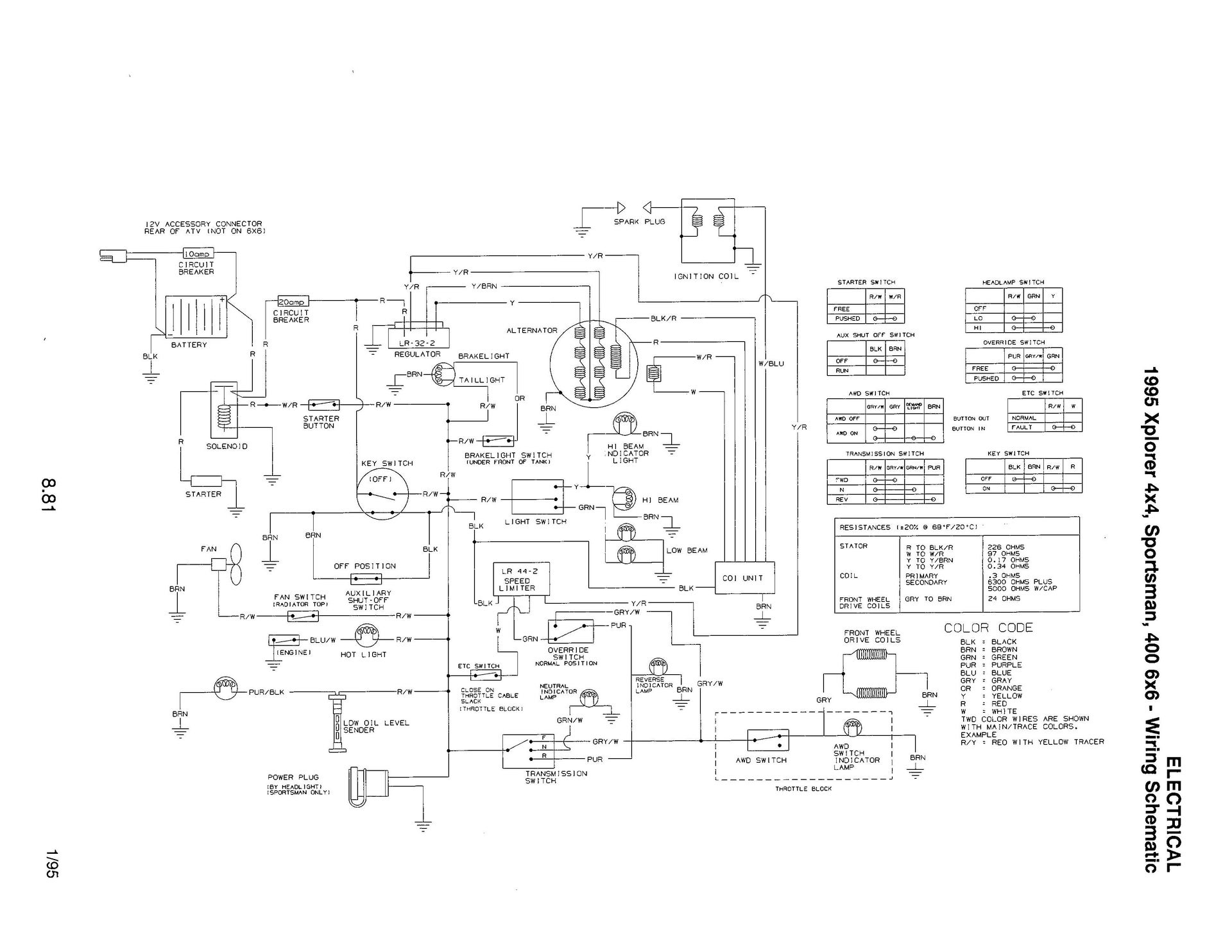
Wiring Schematics:
Polaris CDI wiring diagrams are an essential part of the documentation, providing visual representations of the electrical system’s layout and connections. These schematics enable technicians to trace circuits, identify components, and diagnose electrical faults efficiently.
-
Component Specifications:
The documentation includes detailed specifications for each component within the CDI system, such as the CDI unit, ignition coil, spark plugs, and wiring harness. These specifications provide valuable information on the electrical characteristics, operating parameters, and compatibility of each component.
-
Troubleshooting Procedures:
Step-by-step troubleshooting procedures are an invaluable part of the documentation, guiding technicians through the process of diagnosing and resolving electrical problems. These procedures often involve using diagnostic tools, performing electrical tests, and interpreting diagnostic codes.
-
Maintenance Schedules:
The documentation provides recommended maintenance schedules for the CDI system, including inspection intervals, component replacement guidelines, and general maintenance practices. Adhering to these schedules helps ensure optimal performance and longevity of the electrical system.
In summary, “Documentation: Reference guide for technicians and owners” is an indispensable tool for understanding, maintaining, and troubleshooting Polaris CDI electrical systems. By providing comprehensive wiring schematics, component specifications, troubleshooting procedures, and maintenance schedules, this documentation empowers technicians and owners to confidently service and maintain their vehicles.


Related Posts


