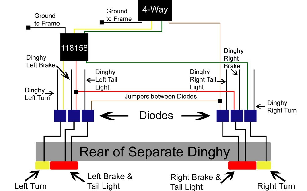
A Pj trailer wiring diagram visually represents the electrical circuitry of a Pj trailer. For instance, a 7-way Pj trailer wiring diagram illustrates the proper wiring connections between the trailer and the towing vehicle, including the brake lights, turn signals, tail lights, auxiliary power, ground, and reverse lights.
Pj trailer wiring diagrams are crucial for safe and compliant trailer operation. They ensure that all electrical systems function correctly, improving visibility, communication, and braking efficiency while reducing the risk of accidents. A pivotal historical development was the standardization of trailer wiring color codes, enhancing compatibility and simplifying installation.
This article delves into the intricacies of Pj trailer wiring diagrams, exploring their components, variations, and troubleshooting techniques. It provides comprehensive guidance for understanding and maintaining these electrical schematics, ensuring the safe and reliable operation of Pj trailers.
Pj trailer wiring diagrams are essential for understanding and maintaining electrical systems in Pj trailers. They provide a visual representation of the wiring connections, ensuring safe and compliant trailer operation.
- Components: Brakes, lights, power
- Variations: 4-way, 5-way, 7-way
- Color Codes: Standardized for easy identification
- Compatibility: Ensures proper connections
- Safety: Prevents electrical hazards
- Maintenance: Inspection, cleaning, repair
- Troubleshooting: Identifying and fixing electrical issues
- Compatibility: Matching trailer and vehicle systems
- Documentation: Referencing for future maintenance
These aspects are crucial for understanding Pj trailer wiring diagrams. Proper wiring ensures that all electrical components function correctly, improving visibility, communication, and braking efficiency while reducing the risk of accidents. By understanding these aspects, you can ensure the safe and reliable operation of your Pj trailer.
Components
Pj trailer wiring diagrams visually depict the electrical connections between the trailer and the towing vehicle, ensuring that essential components like brakes, lights, and power are properly integrated. These components are crucial for the safe and efficient operation of the trailer.
Brakes, lights, and power form the core of a Pj trailer’s electrical system. The wiring diagram provides a clear understanding of how these components are connected and interact. For example, the diagram specifies the wiring for the brake lights, which illuminate when the brake pedal is pressed, signaling to other vehicles that the trailer is slowing down. Similarly, the wiring for the turn signals and tail lights ensures that other road users can clearly see the trailer’s intended direction of travel and its presence on the road.
Understanding the connection between components, brakes, lights, power, and Pj trailer wiring diagrams is essential for several reasons. First, it enables proper installation and maintenance of the trailer’s electrical system. By following the wiring diagram, you can ensure that all components are correctly connected, reducing the risk of electrical hazards or malfunctions. Second, it allows for efficient troubleshooting. If you encounter any electrical issues with your trailer, such as malfunctioning lights or brakes, the wiring diagram provides a roadmap for identifying the root cause of the problem. By tracing the wiring connections, you can pinpoint the faulty component and take appropriate action.
In conclusion, the connection between components, brakes, lights, power, and Pj trailer wiring diagrams is vital for the safe and reliable operation of Pj trailers. Understanding this relationship empowers you to properly install, maintain, and troubleshoot the trailer’s electrical system, ensuring that all components function as intended.
Variations
Pj trailer wiring diagrams vary in complexity and functionality, with the most common variations being 4-way, 5-way, and 7-way diagrams. These variations reflect the different types of connections and components supported by the trailer’s electrical system.
-
4-way Wiring:
This basic wiring configuration is typically found on small trailers and supports the essential lighting functions, including tail lights, brake lights, and turn signals. It utilizes a 4-pin connector.
-
5-way Wiring:
An intermediate configuration, 5-way wiring adds reverse lights to the 4-way setup. It is commonly used on trailers that require additional visibility when reversing, such as boat trailers or cargo trailers. It employs a 5-pin connector.
-
7-way Wiring:
The most comprehensive configuration, 7-way wiring, is designed for larger trailers and supports auxiliary functions beyond lighting. It includes connections for electric brakes, battery charging, and auxiliary power. This versatile wiring system is commonly found on travel trailers, horse trailers, and utility trailers. It utilizes a 7-pin connector.
Understanding the variations in Pj trailer wiring diagrams is crucial for ensuring proper installation, maintenance, and troubleshooting. By matching the wiring diagram to the specific trailer and towing vehicle requirements, you can guarantee the safe and reliable operation of the trailer’s electrical system.
Color Codes
Color codes play a crucial role in Pj trailer wiring diagrams, ensuring easy identification and simplifying the installation and maintenance process. By adhering to standardized color codes, manufacturers and technicians can quickly and accurately determine the purpose of each wire, reducing the risk of errors and ensuring proper functionality of the trailer’s electrical system.
Real-life examples of standardized color codes in Pj trailer wiring diagrams include:
- Brown: Ground
- Red: Right turn/brake
- Yellow: Left turn/brake
- Green: Tail lights
- Blue: Electric brakes
- Black: Auxiliary power
These standardized colors provide a consistent reference point for technicians, regardless of the manufacturer or model of the trailer. By following these color codes, they can quickly identify the correct wires to connect, reducing the risk of misconnections and ensuring the proper functioning of all electrical components.
Understanding the connection between color codes and Pj trailer wiring diagrams is essential for safe and reliable trailer operation. Standardized color codes enable efficient troubleshooting, allowing technicians to quickly identify and resolve electrical issues. They also simplify the process of adding or modifying electrical components, as technicians can easily identify the correct wires to connect to. Additionally, standardized color codes facilitate communication between manufacturers, technicians, and trailer owners, ensuring a common language for discussing and resolving electrical issues.
Compatibility
In the context of Pj Trailer Wiring Diagrams, compatibility plays a pivotal role in ensuring the proper functionality and safety of the trailer’s electrical system. Compatibility encompasses several facets, each contributing to the seamless integration and reliable operation of the trailer’s electrical components.
- Matching Connector Types: Pj Trailer Wiring Diagrams guide the correct matching of connector types between the towing vehicle and the trailer. Proper matching ensures a secure and weather-resistant connection, preventing electrical malfunctions and hazards.
- Standardized Color Coding: Adherence to standardized color coding simplifies the identification and connection of wires, reducing the risk of errors. Universal color codes facilitate compatibility across different trailer manufacturers and models, ensuring consistent and reliable wiring practices.
- Amperage and Voltage Matching: Compatibility considerations extend to matching the amperage and voltage requirements of the electrical components. Overloading or underpowering can lead to damage or malfunctions. Pj Trailer Wiring Diagrams specify the appropriate amperage and voltage ratings, ensuring compatibility between the towing vehicle and the trailer’s electrical system.
- Electrical Load Considerations: Proper wiring diagrams account for the total electrical load of the trailer, including lighting, brakes, and auxiliary devices. Exceeding the capacity of the wiring system can result in overheating, voltage drop, and potential fire hazards. Compatibility ensures that the wiring diagram accommodates the trailer’s electrical load, preventing such risks.
The compatibility considerations outlined in Pj Trailer Wiring Diagrams are essential for maintaining a safe and reliable electrical connection between the towing vehicle and the trailer. By adhering to these compatibility guidelines, users can ensure the proper functioning of all electrical components, minimizing the risk of electrical hazards and maximizing the trailer’s operational efficiency.
Safety
Pj Trailer Wiring Diagrams play a critical role in ensuring the electrical safety of trailers by minimizing the risk of electrical hazards. These hazards can stem from various factors, ranging from improper wiring to overloading, and can lead to serious consequences such as electrical fires, malfunctions, and accidents.
-
Proper Grounding:
Ensuring proper grounding through the wiring diagram prevents electrical shocks and fires by providing a safe path for excess electricity to dissipate. Ground wires, typically colored green, connect the trailer’s frame to the electrical system, providing a crucial safety measure.
-
Overload Protection:
Wiring diagrams incorporate fuses or circuit breakers to protect the electrical system from overloads. These devices prevent damage to electrical components and wiring by interrupting the circuit when excessive current flows, reducing the risk of overheating and electrical fires.
-
Weather Resistance:
Properly designed wiring diagrams consider the harsh outdoor conditions trailers often encounter. Waterproof connectors and corrosion-resistant materials prevent moisture and dirt from compromising the electrical system, ensuring reliable operation and minimizing the risk of electrical malfunctions.
-
Circuit Isolation:
Wiring diagrams isolate individual circuits, preventing electrical problems in one circuit from affecting others. This isolation enhances the safety and reliability of the trailer’s electrical system, reducing the likelihood of cascading failures and ensuring the proper functioning of critical components.
By addressing these safety concerns, Pj Trailer Wiring Diagrams contribute significantly to the overall safety and reliability of trailers. They provide a roadmap for proper installation and maintenance practices, enabling users to minimize electrical hazards and ensure the safe operation of their trailers.
Maintenance
Maintenance, encompassing inspection, cleaning, and repair, is an essential aspect of Pj Trailer Wiring Diagrams. Regular maintenance ensures the proper functioning, safety, and longevity of the trailer’s electrical system.
-
Inspection:
Regular visual inspections of the wiring harness, connectors, and terminals help identify potential issues such as loose connections, corrosion, or damage. Early detection allows for timely repairs, preventing more severe problems.
-
Cleaning:
Dirt, moisture, and corrosion can impair the electrical connections within the wiring diagram. Periodic cleaning removes these contaminants, ensuring optimal conductivity and preventing malfunctions.
-
Connector Maintenance:
Connectors are crucial for establishing secure electrical connections. Proper maintenance involves inspecting for damage, cleaning corrosion, and applying dielectric grease to prevent moisture ingress.
-
Grounding Check:
Grounding provides a safe path for excess electricity to dissipate, preventing electrical shocks and fires. Regular checks ensure that the grounding system is intact and functioning correctly.
By adhering to a regular maintenance schedule, trailer owners can proactively address potential electrical issues, minimize the risk of breakdowns, and prolong the lifespan of their trailer’s wiring system. Moreover, proper maintenance contributes to the overall safety and reliability of the trailer, ensuring a secure and enjoyable trailering experience.
Troubleshooting
Troubleshooting electrical issues is a critical aspect of Pj Trailer Wiring Diagrams, ensuring that the trailer’s electrical system functions correctly and safely. By understanding potential problems and their solutions, users can effectively identify and resolve electrical faults, minimizing downtime and maintaining a reliable trailer.
-
Identifying Malfunctioning Components:
Wiring diagrams help pinpoint faulty components by providing a visual representation of the electrical system. By tracing circuits and checking connections, users can isolate the source of the problem, such as a blown fuse, loose wire, or malfunctioning switch. -
Electrical Testing:
Using a multimeter or test light, technicians can measure voltage, continuity, and resistance to diagnose electrical issues accurately. By comparing readings against specified values, they can identify open circuits, short circuits, or faulty grounds. -
Grounding Verification:
Grounding issues can cause various electrical problems. Troubleshooting involves checking the continuity of the ground wire and ensuring a secure connection to the trailer’s frame. This verification helps eliminate grounding faults and ensures proper functioning of electrical components. -
Circuit Tracing:
Wiring diagrams allow technicians to trace individual circuits, identifying wire colors, connection points, and component locations. By systematically following the circuit path, they can pinpoint issues such as broken wires, loose terminals, or incorrect connections.
Effectively troubleshooting electrical issues with the aid of Pj Trailer Wiring Diagrams requires a combination of technical knowledge, logical reasoning, and meticulous attention to detail. By understanding the principles of electrical circuits, utilizing appropriate testing equipment, and carefully following the wiring diagrams, users can diagnose and resolve electrical problems efficiently, ensuring the safety and reliability of their trailers.
Compatibility
Compatibility is a crucial aspect of Pj Trailer Wiring Diagrams, ensuring that the electrical systems of the towing vehicle and the trailer operate seamlessly together. Matching the trailer’s electrical system to the vehicle’s capabilities is essential for safe and reliable trailer operation.
- Connector Types: Wiring diagrams specify the types of connectors used for the trailer and vehicle, ensuring a secure and weatherproof connection. Matching connectors prevents electrical malfunctions and hazards.
- Electrical Load: The trailer’s electrical load must be compatible with the vehicle’s electrical system. Exceeding the vehicle’s capacity can strain the electrical system, leading to overheating, voltage drop, and potential fire hazards.
- Lighting Compatibility: The trailer’s lighting system must be compatible with the vehicle’s lighting controls. This ensures that the trailer’s lights function correctly and are synchronized with the vehicle’s lighting system.
- Braking Systems: For trailers equipped with electric brakes, the vehicle must have a compatible brake controller. Matching the brake controller to the trailer’s braking system ensures optimal braking performance and prevents premature wear or damage to the brakes.
Matching trailer and vehicle systems through Pj Trailer Wiring Diagrams promotes safety, reliability, and efficient operation. It ensures that the electrical systems of both the vehicle and trailer are compatible, reducing the risk of electrical issues, malfunctions, and accidents. By adhering to the compatibility guidelines outlined in the wiring diagrams, users can confidently connect their trailers to their vehicles, ensuring a seamless and safe trailering experience.
Documentation
Pj Trailer Wiring Diagrams serve as essential documentation for the maintenance and repair of trailer electrical systems. They provide a comprehensive reference point for technicians, enabling them to troubleshoot problems, identify replacement parts, and ensure the proper functioning of the trailer’s electrical components.
-
Component Identification:
Wiring diagrams clearly label and identify each component within the trailer’s electrical system. This documentation aids in locating specific components for inspection, repair, or replacement.
-
Parts List:
Many wiring diagrams include a list of parts used in the electrical system. This information assists in identifying compatible replacement parts and ordering the necessary components for repairs.
-
Troubleshooting Guide:
Some wiring diagrams incorporate troubleshooting guides that provide step-by-step instructions for diagnosing and resolving common electrical issues. These guides help technicians quickly identify and address problems, minimizing downtime.
-
Modification Tracking:
As trailers undergo modifications, such as the addition of accessories or changes to the electrical system, wiring diagrams serve as a valuable record of these alterations. This documentation ensures that future maintenance and repairs are performed with the most up-to-date information.
The documentation provided by Pj Trailer Wiring Diagrams plays a crucial role in maintaining the safety, reliability, and longevity of trailers. By providing a detailed reference for future maintenance, these diagrams empower technicians with the knowledge and resources necessary to effectively diagnose, repair, and modify trailer electrical systems.


Related Posts


