A Pioneer FH-S52BT Wiring Diagram is a schematic representation of the electrical connections within the Pioneer FH-S52BT car stereo. It provides a visual guide to the wiring harness, allowing installers to correctly connect the stereo to the vehicle’s electrical system. This ensures that the stereo functions properly and safely.
Wiring diagrams are essential for any electrical installation, as they prevent incorrect connections that could damage equipment or pose safety hazards. They are particularly important for car stereos, as improper wiring can lead to electrical problems, audio quality issues, or even fire. The Pioneer FH-S52BT Wiring Diagram helps ensure that the stereo is installed correctly and operates as intended.
Wiring diagrams have a long history in electrical engineering, dating back to the early days of electricity. They have played a crucial role in the development of electrical infrastructure, from power plants to home appliances. Today, wiring diagrams are an indispensable tool for electricians, technicians, and anyone working with electrical systems.
Understanding the key aspects of the Pioneer FH-S52BT Wiring Diagram is essential for anyone installing or troubleshooting this car stereo. These aspects encompass various dimensions, providing a comprehensive understanding of the diagram’s role, components, and significance.
- Wiring Harness: The physical connector that links the car stereo to the vehicle’s electrical system.
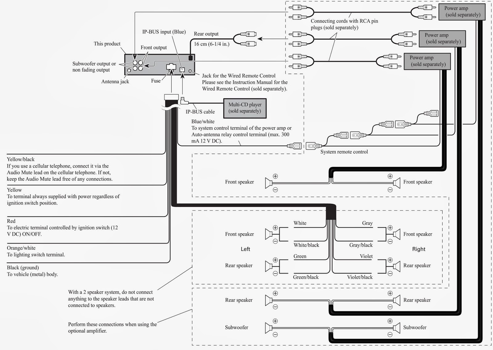
- Color Coding: Each wire in the harness is color-coded to indicate its function, simplifying the identification process.
- Power Connections: Clear identification of the wires responsible for providing power to the stereo.
- Ground Connection: Proper grounding ensures the safe and stable operation of the stereo.
- Speaker Connections: Accurate wiring of the speaker wires ensures optimal audio output.
- Antenna Connection: The diagram guides the connection of the antenna wire to receive radio signals.
- Accessory Connections: Instructions for connecting additional devices, such as amplifiers or steering wheel controls.
- Safety Precautions: Important safety guidelines to prevent electrical hazards during installation.
These key aspects provide a comprehensive understanding of the Pioneer FH-S52BT Wiring Diagram, enabling installers to connect the stereo correctly and safely. Proper wiring ensures optimal performance, prevents damage to equipment, and enhances the overall audio experience.
Wiring Harness
The wiring harness is a critical component of the Pioneer FH-S52BT Wiring Diagram, as it provides the physical connection between the car stereo and the vehicle’s electrical system. Without the wiring harness, the stereo would not be able to receive power, ground itself, or connect to the speakers. The wiring harness ensures that all of the necessary electrical connections are made correctly and securely.
In real-life applications, the wiring harness is typically a color-coded bundle of wires that is connected to the back of the car stereo. The Pioneer FH-S52BT Wiring Diagram provides instructions on which wires to connect to which terminals on the stereo. By following the diagram carefully, installers can ensure that the wiring harness is connected correctly.
Understanding the connection between the wiring harness and the Pioneer FH-S52BT Wiring Diagram is essential for anyone installing or troubleshooting this car stereo. By following the diagram and using the correct wiring harness, installers can ensure that the stereo is connected properly and safely. This will prevent damage to the stereo or the vehicle’s electrical system, and it will ensure that the stereo functions as intended.
Color Coding
The Pioneer FH-S52BT Wiring Diagram leverages color coding as a crucial component, simplifying the identification and connection of wires within the car stereo’s wiring harness. Each wire is assigned a specific color, corresponding to its designated function. This color-coding scheme plays a vital role in streamlining the installation process, particularly for individuals without extensive electrical expertise.
In real-life applications, the Pioneer FH-S52BT Wiring Diagram’s color coding proves invaluable. By following the diagram’s instructions and matching the wire colors to their corresponding terminals, installers can confidently establish secure connections. This eliminates guesswork and reduces the risk of incorrect wiring, which could lead to electrical issues or damage to the stereo or vehicle.
Understanding the significance of color coding in the Pioneer FH-S52BT Wiring Diagram empowers installers with the ability to perform accurate and efficient installations. This practical understanding contributes to the overall success of the stereo’s integration into the vehicle’s electrical system, ensuring reliable performance and optimal audio quality for an enhanced driving experience.
Power Connections
The Pioneer FH-S52BT Wiring Diagram plays a crucial role in identifying the wires responsible for providing power to the stereo. These power connections are critical for the proper functioning of the stereo, as they supply the necessary voltage to operate its various components. Without a clear understanding of these power connections, installers may encounter difficulties in ensuring that the stereo receives the correct power supply.
In real-life applications, the Pioneer FH-S52BT Wiring Diagram provides detailed instructions on which wires to connect to the stereo’s power terminals. By following the diagram’s instructions, installers can confidently establish secure power connections, ensuring that the stereo receives the necessary voltage to operate optimally. This eliminates guesswork and reduces the risk of incorrect wiring, which could lead to electrical issues or damage to the stereo.
Understanding the significance of power connections in the Pioneer FH-S52BT Wiring Diagram empowers installers with the ability to perform accurate and efficient installations. This practical understanding contributes to the overall success of the stereo’s integration into the vehicle’s electrical system, ensuring reliable performance and optimal audio quality for an enhanced driving experience.
Ground Connection
Grounding is a crucial component in the Pioneer FH-S52BT Wiring Diagram, serving as the foundation for the stereo’s safe and stable operation. Without proper grounding, the stereo may experience electrical issues, reduced performance, or even damage. The Pioneer FH-S52BT Wiring Diagram provides clear instructions on the grounding process, ensuring that installers can establish a secure and reliable ground connection.
In real-life applications, the grounding wire in the Pioneer FH-S52BT Wiring Diagram is typically black in color. By following the diagram’s instructions and connecting the black wire to a suitable grounding point on the vehicle’s chassis, installers can create a low-resistance path for electrical current to flow. This prevents the buildup of static electricity and ensures that the stereo is properly grounded.
Understanding the significance of grounding in the Pioneer FH-S52BT Wiring Diagram empowers installers with the ability to perform accurate and efficient installations. This practical understanding contributes to the overall success of the stereo’s integration into the vehicle’s electrical system, ensuring reliable performance and optimal audio quality for an enhanced driving experience.
Speaker Connections
In the Pioneer FH-S52BT Wiring Diagram, speaker connections play a crucial role in delivering optimal audio output. Accurate wiring of the speaker wires ensures that the audio signals from the stereo are transmitted to the speakers with minimal distortion or interference. The Pioneer FH-S52BT Wiring Diagram provides detailed instructions on how to connect the speaker wires to the stereo and to the speakers themselves, ensuring proper polarity and impedance matching.
Real-life examples of the importance of speaker connections in the Pioneer FH-S52BT Wiring Diagram can be seen in car audio systems. If the speaker wires are not connected properly, the audio output may be weak, distorted, or nonexistent. In some cases, incorrect speaker connections can even damage the stereo or the speakers themselves.
Understanding the significance of speaker connections in the Pioneer FH-S52BT Wiring Diagram empowers installers with the ability to perform accurate and efficient installations. This practical understanding contributes to the overall success of the stereo’s integration into the vehicle’s audio system, ensuring reliable performance and optimal audio quality for an enhanced driving experience.
Antenna Connection
In the Pioneer FH-S52BT Wiring Diagram, the antenna connection plays a crucial role in enabling the car stereo to receive radio signals. Without a properly connected antenna, the stereo would be unable to tune into radio stations, resulting in a limited audio experience for the user.
The antenna connection in the Pioneer FH-S52BT Wiring Diagram is typically a single wire, usually blue in color, which needs to be connected to the antenna terminal on the back of the car stereo. The other end of the antenna wire should be connected to a suitable antenna, such as a roof-mounted or windshield-mounted antenna.
Understanding the significance of the antenna connection in the Pioneer FH-S52BT Wiring Diagram empowers installers with the ability to perform accurate and efficient installations. This practical understanding contributes to the overall success of the stereo’s integration into the vehicle’s audio system, ensuring reliable performance and optimal audio quality for an enhanced driving experience.
Accessory Connections
Within the comprehensive Pioneer FH-S52BT Wiring Diagram, accessory connections hold significant importance, enabling the integration of additional devices that enhance the car audio experience. These connections provide clear instructions for installers to seamlessly connect amplifiers, steering wheel controls, and other compatible peripherals.
- Amplifier Connection: By following the diagram’s guidelines, installers can connect an external amplifier to boost the audio output power, resulting in a more immersive and dynamic listening experience.
- Steering Wheel Control Interface: The wiring diagram provides instructions for interfacing the car stereo with steering wheel controls, allowing drivers to conveniently operate audio functions without taking their hands off the wheel.
- Rear Camera Input: For added safety and convenience, the diagram includes instructions for connecting a rear camera to the car stereo, enabling drivers to view the rear surroundings when reversing.
- Auxiliary Input: The diagram also guides installers in connecting auxiliary devices, such as portable music players or smartphones, to the car stereo via an auxiliary input port, allowing for a wider range of audio sources.
Understanding and utilizing the accessory connections outlined in the Pioneer FH-S52BT Wiring Diagram empower installers to customize and enhance the car audio system, tailoring it to meet specific needs and preferences. These connections not only expand the functionality of the car stereo but also contribute to a more enjoyable and convenient driving experience.
Safety Precautions
Within the Pioneer FH-S52BT Wiring Diagram, safety precautions occupy a prominent position, providing indispensable guidelines to prevent electrical hazards during the installation process. These precautions serve as a critical component of the diagram, ensuring that installers adhere to established safety protocols and minimize the risk of electrical accidents.
The importance of safety precautions within the Pioneer FH-S52BT Wiring Diagram cannot be overstated. Electrical installations, particularly those involving car audio systems, carry inherent risks that must be carefully managed. By following the safety guidelines outlined in the diagram, installers can safeguard themselves and prevent damage to the car’s electrical system or the stereo components.
Real-life examples of safety precautions within the Pioneer FH-S52BT Wiring Diagram include clear instructions for:
- Proper handling and connection of electrical wires to avoid short circuits and electrical fires.
- Adequate insulation of electrical connections to prevent accidental contact and potential shocks.
- Correct grounding of the stereo to ensure a stable electrical connection and minimize interference.
- Use of appropriate tools and materials, such as insulated screwdrivers and crimp connectors, to ensure safe and secure installations.
Understanding and applying the safety precautions outlined in the Pioneer FH-S52BT Wiring Diagram empower installers to approach electrical installations with confidence and competence. By adhering to these guidelines, installers can mitigate risks, prevent accidents, and ensure the safe and reliable operation of the car audio system.


Related Posts


