A Pioneer Avh Wiring Diagram outlines the electrical connections required to install a Pioneer in-dash receiver into a vehicle. It typically specifies the color-coded wires for power, ground, speakers, and other components, ensuring proper functioning and compatibility. For instance, a wire harness adapter may be utilized to interface between the Pioneer receiver and the vehicle’s existing wiring, simplifying installation.
Wiring diagrams are crucial for ensuring safe and reliable installation, preventing potential electrical issues or damage. They provide a comprehensive guide for both professional installers and DIY enthusiasts. Historically, paper-based wiring diagrams have been widely used, but digital formats have become increasingly prevalent, offering interactive features and convenient access through online databases.
This article delve into the intricacies of Pioneer Avh Wiring Diagrams, exploring their significance, benefits, and various aspects to consider during installation. We will also provide additional resources and insights to aid in the successful implementation of Pioneer in-dash receivers.
Wiring diagrams are essential for guiding the installation of Pioneer Avh in-dash receivers. Here are eight key aspects to consider:
- Compatibility: Ensures the wiring diagram aligns with the specific Pioneer Avh model and vehicle.
- Color Coding: Facilitates easy identification and connection of wires based on their colors.
- Power Requirements: Specifies the necessary power connections for the receiver to function.
- Grounding: Establishes a proper ground connection for the receiver’s electrical system.
- Speaker Connections: Outlines the wiring for connecting speakers to the receiver.
- Accessory Connections: Details the wiring for connecting additional accessories, such as steering wheel controls.
- Wire Harness Adapters: Describes how to use adapters to interface with the vehicle’s existing wiring.
- Safety Precautions: Highlights important safety measures to follow during installation.
Understanding these aspects helps ensure a successful and problem-free installation. For instance, proper color coding prevents incorrect connections, while grounding ensures electrical stability. Furthermore, using the correct wire harness adapter simplifies installation and maintains compatibility with the vehicle’s electrical system. Adhering to safety precautions minimizes the risk of electrical hazards and ensures a secure setup.
Compatibility
Compatibility between the wiring diagram and the specific Pioneer Avh model and vehicle is paramount for successful installation and operation. The wiring diagram provides a roadmap for connecting the receiver to the vehicle’s electrical system, ensuring that power, ground, speakers, and other components are properly integrated. Using a compatible wiring diagram is essential to avoid electrical issues, malfunctions, or damage to the receiver or vehicle.
Real-life examples underscore the importance of compatibility. For instance, a wiring diagram designed for a Pioneer Avh-Z5200BT receiver may not be compatible with a Pioneer Avh-X390BS model due to differences in their electrical configurations. Similarly, a wiring diagram for a 2015 Honda Civic may not be suitable for a 2023 Toyota Camry due to variations in the vehicle’s electrical architecture.
Understanding the connection between compatibility and Pioneer Avh wiring diagrams has several practical applications. It enables installers to select the correct wiring diagram for their specific receiver and vehicle, ensuring a seamless and reliable installation. Additionally, it helps troubleshoot issues that may arise due to compatibility problems, such as incorrect wiring or electrical malfunctions.
In conclusion, compatibility between the wiring diagram and the specific Pioneer Avh model and vehicle is a critical aspect of successful installation and operation. Using a compatible wiring diagram minimizes the risk of electrical issues, enhances the receiver’s performance, and ensures a safe and reliable in-dash entertainment experience.
Color Coding
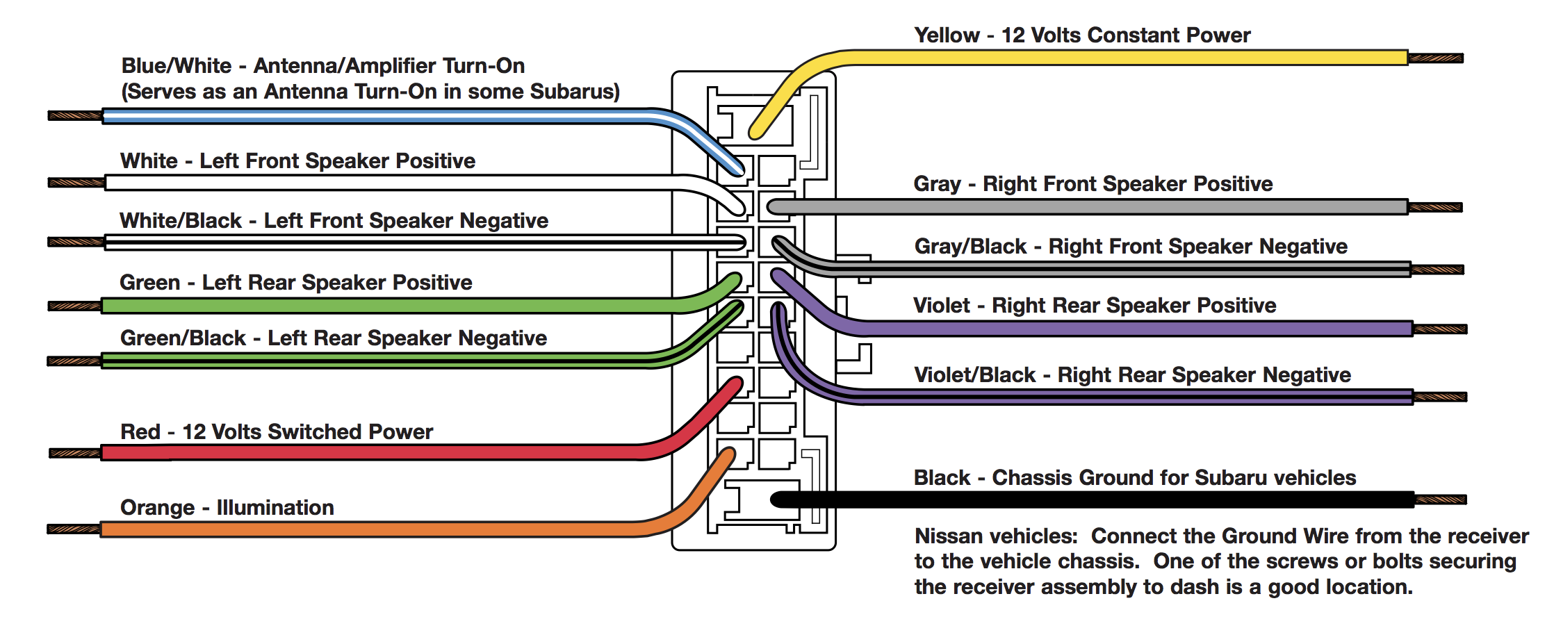
Within the context of Pioneer Avh Wiring Diagrams, color coding plays a critical role in ensuring the correct identification and connection of wires. Each wire is assigned a specific color, which corresponds to its function within the electrical system. This standardized color coding simplifies the installation process, allowing installers to quickly and easily identify the correct wires to connect, thus minimizing the risk of incorrect connections and electrical issues.
For instance, in a typical Pioneer Avh Wiring Diagram, the constant power wire is usually red, the ground wire is black, and the speaker wires are color-coded according to their respective channels (e.g., front left, front right, rear left, rear right). By adhering to this color coding scheme, installers can confidently connect the receiver to the vehicle’s electrical system, ensuring proper functionality and preventing potential damage.
Understanding the connection between color coding and Pioneer Avh Wiring Diagrams has several practical applications. Firstly, it enables installers to verify the accuracy of their connections, reducing the likelihood of errors and subsequent electrical problems. Secondly, it facilitates troubleshooting in the event of malfunctions, as installers can quickly identify the affected wires based on their colors. Thirdly, it allows for easier modifications or upgrades to the audio system, as installers can readily identify the wires that need to be modified or replaced.
In conclusion, color coding is an essential component of Pioneer Avh Wiring Diagrams, providing a simplified and standardized method for identifying and connecting wires. This color coding scheme enhances the ease and accuracy of installation, minimizes the risk of electrical issues, and facilitates troubleshooting and system modifications, ultimately contributing to a successful and reliable in-dash entertainment experience.
Power Requirements
Within the context of Pioneer Avh Wiring Diagrams, understanding the power requirements is crucial for ensuring the proper functioning and longevity of the in-dash receiver. The wiring diagram outlines the necessary electrical connections to provide the receiver with the appropriate power it needs to operate.
-
Constant Power Connection
The constant power connection provides a continuous power supply to the receiver, even when the vehicle is turned off. This connection is typically used to maintain the receiver’s memory settings, such as radio presets and clock settings.
-
Switched Power Connection
The switched power connection provides power to the receiver when the vehicle’s ignition is turned on. This connection allows the receiver to turn on and off in conjunction with the vehicle’s electrical system.
-
Ground Connection
The ground connection establishes a reference point for the electrical system and completes the circuit. A proper ground connection is essential for the receiver to function correctly and prevent electrical issues.
-
Fuse Protection
The wiring diagram may specify the use of fuses to protect the receiver and the vehicle’s electrical system from power surges or short circuits. Fuses are designed to blow and interrupt the current flow in the event of an electrical fault.
Understanding the power requirements and adhering to the wiring diagram’s specifications help ensure that the Pioneer Avh receiver receives the correct amount of power, minimizing the risk of damage or malfunctions. Proper power connections also contribute to the stable and reliable operation of the receiver, enhancing the overall in-dash entertainment experience.
Grounding
Grounding is a crucial aspect of Pioneer Avh Wiring Diagrams, providing a stable reference point for the electrical system and completing the circuit. A proper ground connection ensures that the receiver’s electrical components are properly earthed, preventing electrical noise, malfunctions, and potential damage.
In Pioneer Avh Wiring Diagrams, the ground connection is typically indicated by a black wire. This wire must be connected to a suitable grounding point in the vehicle’s chassis, which provides a low-resistance path for electrical current to flow back to the negative terminal of the battery. Without a proper ground connection, the receiver may experience various issues, including poor sound quality, intermittent operation, and even electrical shorts.
Understanding the importance of grounding in Pioneer Avh Wiring Diagrams has several practical applications. Firstly, it enables installers to identify and resolve grounding issues that may arise during installation, ensuring optimal performance and reliability of the receiver. Secondly, it helps prevent electrical problems that could potentially damage the receiver or other components in the vehicle’s electrical system. Thirdly, a proper ground connection contributes to better sound quality by reducing electrical noise and interference.
In conclusion, grounding plays a critical role in Pioneer Avh Wiring Diagrams, ensuring a stable and reliable electrical connection for the receiver. Understanding the importance of grounding and adhering to the specifications outlined in the wiring diagram are essential for successful installation and operation of the in-dash receiver, enhancing the overall audio experience and safeguarding the electrical system of the vehicle.
Speaker Connections
Within the context of Pioneer Avh Wiring Diagrams, speaker connections play a crucial role in establishing a functional audio system. The wiring diagram provides detailed instructions on how to connect the receiver to the vehicle’s speakers, ensuring optimal sound output and a seamless listening experience.
-
Speaker Wire Gauge
The wiring diagram specifies the appropriate gauge of speaker wire to use, which determines the wire’s thickness and current-carrying capacity. Using the correct wire gauge ensures efficient power transfer and minimizes signal loss.
-
Speaker Polarity
The diagram indicates the correct polarity of the speaker connections, ensuring that the positive and negative terminals of the speaker are connected to the corresponding terminals on the receiver. Proper polarity is essential for accurate sound reproduction and balanced audio output.
-
Speaker Impedance
The wiring diagram may provide information on the impedance of the speakers, which is typically measured in ohms. Matching the receiver’s output impedance to the speaker impedance ensures optimal power transfer and prevents damage to the receiver or speakers.
-
Speaker Placement
Although not directly specified in the wiring diagram, the placement of the speakers within the vehicle can affect the overall sound quality. The diagram may provide general guidelines or recommendations for speaker placement to achieve the desired soundstage and listening experience.
Understanding and adhering to the speaker connection guidelines outlined in Pioneer Avh Wiring Diagrams are critical for achieving a well-integrated and high-quality audio system. Proper speaker connections ensure efficient power transfer, accurate sound reproduction, and optimal listening enjoyment.
Accessory Connections
Accessory connections are a vital aspect of Pioneer Avh Wiring Diagrams. They provide instructions on how to connect various accessories to the receiver, including steering wheel controls, Bluetooth modules, and external amplifiers. Understanding these connections is essential for achieving a fully integrated and user-friendly in-dash entertainment system.
One of the most common accessory connections is for steering wheel controls. By connecting the receiver to the vehicle’s steering wheel controls, drivers can safely and conveniently operate audio functions, such as volume adjustment, track skipping, and source selection, without taking their hands off the wheel. The wiring diagram specifies the specific wires that need to be connected to the steering wheel control interface, ensuring compatibility and proper functionality.Real-life examples further highlight the importance of accessory connections in Pioneer Avh Wiring Diagrams. For instance, a Pioneer AVH-Z5200BT receiver may have dedicated wiring connections for steering wheel controls, allowing drivers to seamlessly integrate their existing steering wheel controls with the receiver’s advanced audio features. Similarly, an AVH-X390BS model may provide connections for a Bluetooth module, enabling hands-free calling and wireless music streaming.Understanding the connection between accessory connections and Pioneer Avh Wiring Diagrams has several practical applications. Firstly, it allows installers to identify and connect various accessories, enhancing the functionality and usability of the receiver. Secondly, it helps troubleshoot issues related to accessory connections, such as non-functioning steering wheel controls or Bluetooth connectivity problems. Thirdly, it enables installers to plan and integrate future upgrades or modifications to the audio system, ensuring compatibility with additional accessories.
In conclusion, accessory connections are an integral part of Pioneer Avh Wiring Diagrams, providing a comprehensive guide for connecting a wide range of accessories to enhance the in-dash entertainment experience. By understanding these connections, installers can unlock the full potential of Pioneer receivers, ensuring seamless integration, optimal functionality, and a more enjoyable driving experience.
Wire Harness Adapters
Wire harness adapters play a critical role in the installation of Pioneer AVH receivers, providing a seamless interface between the receiver and the vehicle’s existing wiring harness. They are designed to simplify the installation process, eliminating the need for cutting or splicing wires, and ensuring compatibility with the vehicle’s electrical system.
Pioneer Avh Wiring Diagrams include detailed instructions on how to use wire harness adapters. These instructions specify the specific adapter required for the particular vehicle model and receiver, and provide step-by-step guidance on how to connect the adapter to the receiver and the vehicle’s wiring harness. By following these instructions carefully, installers can ensure a secure and reliable connection, minimizing the risk of electrical issues or damage to the receiver or vehicle.
Real-life examples further highlight the importance of wire harness adapters in Pioneer Avh Wiring Diagrams. For instance, when installing a Pioneer AVH-Z5200BT receiver in a 2018 Toyota Camry, the wiring diagram specifies the use of a specific wire harness adapter, such as the Metra 70-1761. This adapter is designed to match the pin configuration of the receiver’s wiring harness to the Camry’s factory wiring harness, ensuring a seamless connection and compatibility with the vehicle’s features, such as steering wheel controls and vehicle information display.
Understanding the connection between wire harness adapters and Pioneer Avh Wiring Diagrams has several practical applications. Firstly, it enables installers to select and use the correct adapter for their specific vehicle and receiver, ensuring compatibility and ease of installation. Secondly, it helps troubleshoot issues related to electrical connections, such as no power to the receiver or malfunctioning steering wheel controls. Thirdly, it allows installers to plan and integrate future upgrades or modifications to the audio system, ensuring compatibility with additional components or accessories.
In conclusion, wire harness adapters are an essential component of Pioneer Avh Wiring Diagrams, providing a standardized and reliable method for interfacing the receiver with the vehicle’s existing wiring. By understanding the importance of wire harness adapters and following the instructions outlined in the wiring diagram, installers can achieve a successful and trouble-free installation, enhancing the functionality and enjoyment of the in-dash entertainment system.
Safety Precautions
When dealing with electrical components and vehicle systems, adhering to safety precautions outlined in the Pioneer Avh Wiring Diagram is paramount. These precautions are not mere guidelines but critical measures to prevent potential hazards and ensure a successful and safe installation.
-
Disconnect the Battery
Before initiating any wiring work, disconnecting the vehicle’s battery is crucial. This step eliminates the risk of electrical shock or short circuits that could damage the receiver, vehicle, or cause personal injury.
-
Use Proper Tools and Materials
Employing appropriate tools and materials designed for automotive electrical work is essential. Insulated tools, wire strippers, and crimp connectors ensure safe handling of wires and connections, preventing accidental shorts or damage to components.
-
Follow Wiring Color Codes
Pioneer Avh Wiring Diagrams utilize color-coded wires to simplify identification and prevent incorrect connections. Strictly adhering to these color codes ensures proper functionality, eliminates potential electrical issues, and facilitates troubleshooting if needed.
-
Secure Loose Wires
After completing wire connections, it’s imperative to secure any loose wires using electrical tape or zip ties. Loose wires can rattle, causing intermittent connections, electrical noise, or even short circuits.
By observing these safety precautions and meticulously following the instructions provided in the Pioneer Avh Wiring Diagram, installers can mitigate risks associated with electrical work, safeguard their well-being, and achieve a reliable and enjoyable in-dash entertainment system.


Related Posts


