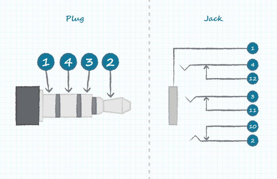
A 3.5 mm female jack wiring diagram outlines the pin connections for a three-pole, five-contact female connector. It serves as a guide for connecting audio and video cables to compatible devices. A common example is the headphone jack found on smartphones, computers, and audio players.
Pinout diagrams are crucial for ensuring proper signal transmission and preventing damage to equipment. They indicate the corresponding pin numbers for each signal (e.g., left audio, right audio, ground) and provide information on shielding and grounding.
The development of standardized pinout diagrams has simplified audio and video connectivity, enabling seamless interoperability between various devices. This has played a significant role in the widespread adoption of electronic devices and interconnected systems.
Understanding the key aspects of “Pinout 3.5 Mm Female Jack Wiring Diagram” is essential for proper audio and video connectivity. These aspects encompass various dimensions related to the wiring diagram itself, the physical connector, and its applications.
- Pin Configuration
- Signal Types
- Shielding and Grounding
- Compatibility
- Connector Dimensions
- Materials and Durability
- Industry Standards
- Troubleshooting
- Safety Considerations
These aspects are interconnected and influence the functionality, reliability, and safety of audio and video systems. Proper understanding of pin configurations ensures correct signal transmission, while shielding and grounding techniques minimize noise and interference. Compatibility considerations allow for seamless connectivity between different devices, and industry standards provide a common framework for interoperability. Troubleshooting techniques help identify and resolve connection issues, enhancing system performance and reliability. Ultimately, these aspects contribute to the effective transmission of audio and video signals, enabling seamless communication and entertainment experiences.
Pin Configuration
Pin configuration is a fundamental aspect of “Pinout 3.5 mm Female Jack Wiring Diagram” as it defines the arrangement and purpose of each pin within the connector. Understanding pin configuration is critical for establishing proper electrical connections and ensuring reliable signal transmission.
-
Pin Numbering
Each pin in the connector is assigned a unique number, which corresponds to its specific function or signal type. This numbering system ensures that pins are correctly identified and connected during wiring. -
Signal Type
Pin configuration determines the type of signal that each pin carries, such as left audio, right audio, ground, or microphone input. This information is essential for connecting the appropriate wires to the correct pins. -
Shielding
Some pins may be shielded to prevent electromagnetic interference (EMI) and ensure signal integrity. Pin configuration diagrams indicate which pins are shielded and how they should be connected to the shielding. -
Keying
Pin configuration can also include a keying mechanism to prevent incorrect insertion of the connector. This ensures that the connector is properly aligned and connected, reducing the risk of damage or malfunction.
Overall, pin configuration is a crucial aspect of “Pinout 3.5 mm Female Jack Wiring Diagram” as it provides a clear roadmap for connecting audio and video signals. By understanding the pin configuration, technicians and hobbyists can ensure proper signal transmission and prevent potential issues.
Signal Types
Signal types are a crucial aspect of “Pinout 3.5 mm Female Jack Wiring Diagram” as they define the nature of the signals transmitted through the connector. Understanding the different signal types is essential for proper wiring and ensuring reliable signal transmission.
-
Audio Signals
Audio signals are electrical signals that represent sound. In a 3.5 mm jack, there are typically three audio signals: left audio, right audio, and ground. -
Video Signals
Video signals are electrical signals that represent images. In a 3.5 mm jack, video signals are typically carried on a single pin. -
Microphone Signals
Microphone signals are electrical signals that represent sound captured by a microphone. In a 3.5 mm jack, microphone signals are typically carried on a single pin. -
Control Signals
Control signals are electrical signals that control the operation of a device. In a 3.5 mm jack, control signals are typically used to control volume, playback, and other functions.
Understanding the different signal types is essential for proper wiring and ensuring reliable signal transmission. By matching the signal type to the correct pin, technicians and hobbyists can ensure that audio, video, and other signals are transmitted correctly and without interference.
Shielding and Grounding
Shielding and grounding are crucial aspects of “Pinout 3.5 mm Female Jack Wiring Diagram” as they play a vital role in ensuring signal integrity and preventing noise interference. Shielding involves enclosing the signal wires within a conductive material, typically metal, to protect them from external electromagnetic interference (EMI) and radio frequency interference (RFI).
Grounding, on the other hand, provides a reference point for the electrical signals and helps to drain away any unwanted electrical noise or currents. In a 3.5 mm jack, the ground pin is typically connected to the metal casing of the connector, which is then connected to the ground of the system. This creates a low-impedance path for noise currents to flow, preventing them from interfering with the signal.
Real-life examples of shielding and grounding within “Pinout 3.5 mm Female Jack Wiring Diagram” can be found in various audio and video applications. For instance, in shielded audio cables, the individual conductors are wrapped in a metal foil or braid to minimize EMI and RFI. Similarly, in video cables, the shielding helps to prevent crosstalk between adjacent conductors, ensuring signal integrity.
Understanding the principles of shielding and grounding is essential for designing and implementing reliable audio and video systems. By incorporating proper shielding and grounding techniques into “Pinout 3.5 mm Female Jack Wiring Diagram,” engineers and technicians can ensure the accurate transmission of signals, minimize noise and interference, and enhance the overall performance of the system.
Compatibility
Compatibility, a fundamental aspect of “Pinout 3.5 Mm Female Jack Wiring Diagram,” ensures seamless interoperability among various components and devices within an audio/video system. This compatibility is achieved by adhering to established standards and specifications, enabling diverse elements to function harmoniously.
-
Connector Standards
Pinout diagrams strictly adhere to industry-defined connector standards, ensuring that jacks and plugs from different manufacturers are physically compatible. This standardization allows for the interchangeable use of components, guaranteeing a secure and reliable connection. -
Signal Compatibility
Signal compatibility is crucial for proper audio/video transmission. Pinout diagrams specify the signal types carried by each pin, such as left/right audio, microphone input, or video signals. Matching the signal types between devices ensures accurate and distortion-free transmission. -
Device Compatibility
Pinout diagrams facilitate compatibility between audio/video devices with varying functionalities. By adhering to standard pin configurations, manufacturers can ensure that headphones, speakers, microphones, and other devices can be easily connected and work seamlessly with various systems. -
System Integration
Compatibility extends beyond individual components to encompass system-level integration. Pinout diagrams enable the integration of audio/video systems into larger setups, such as home theater systems or professional audio installations. By adhering to standard pinouts, system designers can ensure that all components work together harmoniously, delivering an optimal audio/video experience.
Understanding compatibility within “Pinout 3.5 Mm Female Jack Wiring Diagram” is paramount for successful audio/video system design and implementation. It ensures that components can be connected and function seamlessly, avoiding compatibility issues that could lead to improper signal transmission, noise, or even damage to equipment. By adhering to established standards and carefully considering compatibility aspects, engineers and technicians can create robust and high-performing audio/video systems.
Connector Dimensions
Within the realm of “Pinout 3.5 Mm Female Jack Wiring Diagram,” connector dimensions play a pivotal role in ensuring proper physical connections and reliable signal transmission. These dimensions dictate the size, shape, and orientation of the connector, directly affecting the pin configuration and overall functionality of the wiring diagram.
The critical relationship between connector dimensions and pinout diagrams stems from the need for precise alignment and contact between the pins and their corresponding terminals. Each pin within the 3.5 mm female jack is assigned a specific location and orientation based on the connector’s dimensions. This arrangement ensures that the signals carried by each pin are correctly routed and transmitted.
Real-life examples of connector dimensions within “Pinout 3.5 Mm Female Jack Wiring Diagram” can be found in various electronic devices and audio equipment. Smartphones, laptops, and portable media players commonly feature 3.5 mm audio jacks for connecting headphones, speakers, and microphones. The dimensions of these jacks are standardized to ensure compatibility between different devices and accessories.
Understanding the connection between connector dimensions and pinout diagrams has practical applications in various fields. Technicians and engineers rely on this knowledge to design and implement audio systems, ensuring proper signal transmission and preventing damage to equipment. Adhering to the specified connector dimensions and pin configurations guarantees that devices can be connected seamlessly, delivering optimal audio performance.
Materials and Durability
In the context of “Pinout 3.5 Mm Female Jack Wiring Diagram,” materials and durability play a critical role in ensuring the reliability and longevity of the connection. The choice of materials, the design of the connector, and the manufacturing processes employed all contribute to the overall durability and performance of the wiring diagram.
-
Connector Housing
The connector housing, which encloses the pins and terminals, is typically made from durable materials such as plastic or metal. The choice of material depends on the application and the level of durability required. Plastic housings are lightweight and cost-effective, while metal housings provide better shielding and durability in harsh environments.
-
Pin and Terminal Materials
The pins and terminals within the connector are typically made from conductive materials such as copper or gold. Copper is widely used due to its excellent conductivity, while gold plating provides additional corrosion resistance and improves signal transmission.
-
Soldering and Crimping
The method of attaching the wires to the pins and terminals, either through soldering or crimping, affects the durability of the connection. Soldering creates a permanent bond between the wire and the pin/terminal, while crimping provides a secure mechanical connection. The choice of method depends on factors such as the type of wire, the application, and the required level of reliability.
-
Environmental Factors
The durability of the wiring diagram is also influenced by environmental factors such as temperature, humidity, and exposure to chemicals. The materials used in the connector and the design of the housing should be able to withstand the expected environmental conditions to ensure long-term reliability.
Understanding the materials and durability aspects of “Pinout 3.5 Mm Female Jack Wiring Diagram” is crucial for designing and implementing reliable audio and video systems. By choosing appropriate materials, employing robust construction techniques, and considering environmental factors, engineers and technicians can create durable wiring diagrams that will ensure optimal signal transmission and long-lasting performance.
Industry Standards
Industry standards are crucial within the realm of “Pinout 3.5 mm Female Jack Wiring Diagram” as they establish a common framework for the design, implementation, and interoperability of audio and video equipment. These standards ensure that different manufacturers’ components can work together seamlessly, enabling the creation of compatible and reliable systems.
The importance of industry standards lies in their ability to streamline the development and production of audio/video equipment. By adhering to standardized pin configurations, manufacturers can ensure that their products are compatible with a wide range of devices and accessories. This compatibility fosters innovation and promotes the growth of the audio/video industry as a whole.
Real-life examples of industry standards within “Pinout 3.5 mm Female Jack Wiring Diagram” can be found in various applications. The 3.5 mm audio jack is a ubiquitous connector found on smartphones, laptops, portable media players, and other devices. The standardized pin configuration allows for the interchangeable use of headphones, speakers, and microphones, regardless of the manufacturer. This compatibility has played a significant role in the widespread adoption of the 3.5 mm audio jack as a universal audio interface.
Understanding the connection between industry standards and “Pinout 3.5 mm Female Jack Wiring Diagram” has practical applications in the design and implementation of audio/video systems. By adhering to established standards, engineers and technicians can ensure that their systems are compatible with a wide range of components and devices. This compatibility simplifies system integration, reduces the risk of compatibility issues, and enhances the overall reliability and performance of the system.
In conclusion, industry standards are an essential component of “Pinout 3.5 mm Female Jack Wiring Diagram” as they promote compatibility, interoperability, and reliability within the audio/video industry. By adhering to established standards, manufacturers and developers can create products that seamlessly integrate with each other, providing users with a wide range of choices and enhancing the overall experience of audio and video systems.
Troubleshooting
Within the context of “Pinout 3.5 mm Female Jack Wiring Diagram,” troubleshooting plays a crucial role in identifying and resolving issues that may arise during the implementation or usage of audio and video systems. By understanding the potential causes and effects of various problems, engineers and technicians can effectively diagnose and rectify faults, ensuring optimal system performance.
-
Signal Integrity
Signal integrity issues can manifest as distorted audio, flickering video, or complete loss of signal. Troubleshooting involves checking for proper connections, continuity of wires, and the absence of electromagnetic interference. -
Component Malfunction
Faulty components, such as damaged jacks, loose wires, or malfunctioning amplifiers, can disrupt signal transmission. Troubleshooting involves isolating the faulty component through systematic testing and replacement. -
Environmental Factors
External factors, such as temperature fluctuations, humidity, or physical stress, can affect the performance of the wiring diagram. Troubleshooting involves assessing the system’s operating environment and implementing appropriate measures to mitigate any adverse effects. -
Compatibility Issues
Incompatibility between different components or devices can lead to signal issues. Troubleshooting involves verifying that the pin configurations, signal types, and other parameters are correctly matched and compatible.
Effective troubleshooting requires a systematic approach, involving careful examination of the wiring diagram, testing of individual components, and consideration of potential environmental and compatibility factors. By thoroughly understanding the aspects of troubleshooting related to “Pinout 3.5 mm Female Jack Wiring Diagram,” engineers and technicians can efficiently resolve issues, ensuring reliable and high-quality audio and video transmission.
Safety Considerations
Within the context of “Pinout 3.5 mm Female Jack Wiring Diagram,” safety considerations play a critical role in ensuring the safe and reliable operation of audio and video systems. Improper wiring or mishandling of electrical components can lead to electrical hazards, such as short circuits, fires, or electric shock. Understanding and adhering to safety guidelines are paramount to prevent these potential risks.
A fundamental safety consideration is the correct identification and handling of electrical wires. Each wire within the pinout diagram carries a specific voltage or signal, and incorrect connections can lead to damage to equipment or injury. Color-coding and labeling of wires are commonly used to facilitate proper identification and avoid mix-ups.
Furthermore, the design of the connector itself incorporates safety features. The recessed nature of the 3.5 mm jack helps prevent accidental contact with live electrical terminals. Additionally, the use of insulating materials in the connector housing minimizes the risk of electrical shock.
By understanding the safety considerations associated with “Pinout 3.5 mm Female Jack Wiring Diagram,” engineers, technicians, and users can take appropriate measures to ensure safe and reliable operation of audio and video systems. Adhering to established safety guidelines, proper handling of electrical components, and careful attention to detail are essential practices for preventing electrical hazards and promoting a positive user experience.


![[DIAGRAM] 3 5 Mm Jack Diagram](https://i0.wp.com/www.pcboard.ca/image/cache/catalog/products/connectors/3_5-mm_jack_specs-800x800.jpg?resize=665%2C665&ssl=1)


Related Posts


